Kinematic diagram of the drilling machine 2A150
Kinematic diagram of drilling machine 2a150
Description of the kinematic scheme
The kinematic chain of the machine (Fig. 5) serves to carry out two main movements - the rotational movement of the spindle and the vertical movement (feed) of the sleeve with the spindle.
The spindle speed is changed using a gearbox.
The machine mechanisms are driven by an individual electric motor with a power of 7.5 kW via V-belt transmission through pulleys 1 and 2 (type B V-belt; L=1400; GOST 1284-57). Pulley 2 (Fig. 5) is mounted on the first shaft of the gearbox, on which sits a movable block of four gears (3, 4, 5, 6), transmitting rotation to the second shaft through gears 7, 8, 9, 10. From shaft II through fixedly fixed gear II, rotation is transmitted through gear 12 to shaft III, from which rotation through gears 12 and 18 is transmitted to shaft IV. On shaft IV sits a movable block of four gears (13, 14, 15 and 16), which transmits rotation through gears 17 and 19 to shaft V, which is a hollow sleeve, along the splined hole of which the splined end of the spindle moves freely. The feed mechanism receives movement along the following chain: from gear 22, sitting on the splined part of the spindle, through gears 23, 24 and 25, rotation is transmitted to shaft VII, along which a movable triple block of gears 26, 27, 28 moves. This block rotates shaft VIII through gears 29, 30, 31. From shaft VIII, rotation is transmitted to shaft IX through gears 31, 32 and a movable triple block of gears 33, 34 and 35, which transmits rotation through gears 36 and 37 to shaft X. Gear 38 transmits rotation through gear 39 shaft XI, from where, through a cam clutch, rotation is transmitted to shaft XIV and the worm 42 sitting on it. The worm rotates the worm wheel 43 on the horizontal shaft XII, made integral with the rack and pinion gear 44, which is engaged with the rack 56, cut directly on the spindle sleeve.
Thus, the rotational movement of the entire mechanism is converted into translational movement of the spindle.
The working feed of the spindle is carried out using a rack and pinion transmission.
The spindle can also be moved manually using the XII steering wheel mounted on the horizontal shaft. On shaft XII sits gear 46, which through gear 47 transmits rotation to internal gear 45; on the latter there is a dial for setting the drilling depth. Fine manual feed of the spindle is carried out by a handwheel through a pair of bevel gears 40 and 41. The spindle head is raised by rotating the handle on shaft XIII, worm 49, worm wheel 48, rack and pinion 50 and rack 51 mounted on the machine column. The table is raised by rotating the handle through bevel gears 52, 53, screw 55 and nut 54.
The reversal of the spindle, necessary during thread-cutting operations, is carried out by switching the poles of the electric motor.
General information
Drilling and boring machines are designed for processing holes. The following types of drilling machines are used in various industries: single-spindle vertical drilling machines; radial drilling; multi-spindle drilling machines; horizontal drilling for deep drilling; central for obtaining center holes; aggregate drilling and boring; tabletop drilling and specialized drilling machines.
Boring machines can be both general purpose (universal) and specialized.
Universal boring machines are divided into horizontal boring machines; vertical boring; coordinate boring.
The main dimensions characterizing drilling machines are the largest drilling diameter, spindle stroke, number of cone in the spindle hole, etc.
To drilling
General purpose machines include vertical drilling and radial drilling.
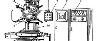
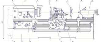
An idea of the design of drilling machines is given by the general view of a radial drilling machine in Fig. 4.3.1.
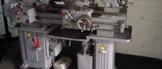
The machine is designed for drilling holes in the ends of the frames of electrical machines, in bearing shields, etc. It is used in electrical engineering.
Drilling machines are usually vertical and contain the following main equipment:
— foundation slab (1) on which a fixed column (2) is installed;
— a hollow sleeve (4), put on a column (2) and rotating 360° around the column;
— a traverse (11) placed on the sleeve, which can be raised and lowered along the column using a screw (8);
— spindle head (10), which can move horizontally along the traverse (11);
— spindle (12) for securing the drill (13), driven by the main motor (9);
— clamping ring (3) for securing the sleeve (4) with the traverse (11) on the column (2); the split ring is tightened using a differential screw, rotated manually or from a separate ED;
— table (14) on which the workpiece is installed; the table can move along guides back and forth to the column;
— an electric drive consisting of a motor that provides the main movement and feed of the spindle; motor rotation of the sleeve (4) with the traverse (11) around the column (2); movement of the traverse vertically;
— movement mechanism (5), which ensures a reduction in the rotational speed of the electric motor to the required one.
Boring
The machines are designed for processing large parts and are usually horizontal. In addition to drilling operations, you can perform milling, threading, etc.
Information about the manufacturer of the vertical drilling machine 2A150
Manufacturer of drilling machines models 2A125, 2A135, 2A150, 2G175, founded in 1941.
The history of the Sterlitamak Machine Tool Plant begins on July 3, 1941, when the evacuation of the Odessa Machine Tool Plant to the city of Sterlitamak began.
Already on October 11, 1941, the Sterlitamak Machine Tool Plant began producing special modular machines for the defense industry.
Currently, the plant produces metalworking equipment, including CNC lathes and milling machines, multifunctional machining centers, metalworking and cutting tools.
2A150 Universal vertical drilling machine. Purpose and scope
The vertical drilling machine 2A150 replaced an outdated model in production 2150
and was replaced by a more advanced model.
The universal vertical drilling machine 2A150 is used in enterprises with single and small-scale production and is designed to perform the following operations: drilling, reaming, countersinking, reaming, and trimming ends with knives.
A universal vertical drilling machine, model 2A150 with a nominal drilling diameter of 50 mm, is designed for work in repair and tool shops, as well as in production shops with small-scale production; equipped with accessories, the machine can be used in mass production (The largest nominal drilling diameter is equal to the maximum diameter of the hole that can be drilled on this machine, using a standard twist drill, in a solid steel workpiece with a tensile strength of 500-600 MPa (steel 45)).
Allows processing of parts in a wide range of sizes from various materials using tools from high-carbon and high-speed steels and hard alloys.
Drilling operations on machine 2a150
Operating principle and design features of the machine
The presence on the machine of a nine-speed gearbox with a control range of 68-100-140-195-175-400-530-750-1100 rpm, an 11-speed feed box with a control range of 0.115 to 1.6 mm per revolution and electric reverse provides selection of standard cutting modes for hole diameters up to 35 mm when drilling, reaming, countersinking, countersinking, reaming, threading, and also allows the use of cutting tools equipped with carbide.
The presence of mechanical spindle feed on machines, with manual control of work cycles.
Allows processing of parts in a wide range of sizes from various materials using tools from high-carbon and high-speed steels and hard alloys.
The machines are equipped with a device for reversing the main motion electric motor, which allows them to cut threads using machine taps while manually feeding the spindle.
Thanks to the presence of a manually controlled electric reverse, it is possible to cut threads by manually approaching and retracting the tap. The permissible number of electric motor reverse strokes is no more than 30 per hour. When cutting threads, a safety chuck should be used.
Placement category 4 according to GOST 15150-69.
Analogues of vertical drilling machines 2A135, currently produced:
- 2T125, 2T140, 2T150 - manufacturer: Gomel Machine Unit Plant
- 2AS132, 2AS132-01 - manufacturer: Astrakhan Machine Tool Plant
- 2L125, 2L132, 2L135, LS25, LS35 - manufacturer: Lipetsk Machine Tool Enterprise (PJSC STP-LSP)
- MN25L, MN25N-01 - manufacturer: Molodechno Machine Tool Plant
Main technical characteristics of the 2A150 machine
| Parameter name | 2A125 | 2A135 | 2A150 |
| Basic machine parameters | |||
| The largest drilling diameter in steel is 45, mm | 25 | 35 | 50 |
| The smallest and largest distance from the end of the spindle to the table, mm | 0… 700 | 0… 750 | 0… 800 |
| The smallest and largest distance from the end of the spindle to the plate, mm | 750… 1125 | 705… 1130 | 650… 1200 |
| Distance from the axis of the vertical spindle to the rack guides (overhang), mm | 250 | 300 | 350 |
| Desktop | |||
| Maximum load on the table (center), kg | |||
| Dimensions of the working surface of the table, mm | 500 x 375 | 450 x 500 | 500 x 600 |
| Number of T-slots Dimensions of T-slots | 3 | 3 | 3 |
| Maximum vertical movement of the table (Z axis), mm | 325 | 325 | 325 |
| Spindle | |||
| Maximum movement of the spindle headstock (spindle slide), mm | 200 | 200 | 250 |
| Maximum movement (stroke) of the spindle, mm | 175 | 225 | 300 |
| Spindle rotation speed, rpm (number of steps) | 97… 1360 (9) | 68… 1100 (9) | 32… 1400 (12) |
| Number of spindle speeds | 9 | 9 | 12 |
| Maximum permissible torque, N*m (kgf*m) | 250 | 400 | 800 |
| Spindle taper | Morse 3 | Morse 4 | Morse 5 |
| Machine mechanics | |||
| Number of working feed stages | 9 | 11 | 9 |
| Limits of vertical working feeds per spindle revolution, mm (number of steps) | 0,1… 0,81 (9) | 0,115… 1,6 (11) | 0,12… 2,64 (9) |
| Maximum feed force, N (kgf) | 9000 (900) | 16000 (1600) | 25000 (2500) |
| Dynamic spindle braking | Eat | Eat | Eat |
| Electrical equipment and machine drive | |||
| Main motion drive electric motor, kW | 2,8 | 4,5 | 7,5 |
| Electric coolant pump Type | X14-22M | X14-22M | X14-22M |
| Dimensions and weight of the machine | |||
| Machine dimensions (length x width x height), mm | 980 x 825 x 2300 | 1240 x 810 x 2500 | 1550 x 970 x 2865 |
| Machine weight, kg | 870 | 1300 | 2250 |
- Universal vertical drilling machine model 2A150. Manual, 1960
- Barun V.A. Working on drilling machines, 1963
- Vinnikov I.Z., Frenkel M.I. Driller, 1971
- Vinnikov I.Z. Drilling machines and work on them, 1988
- Loskutov V.V Drilling and boring machines, 1981
- Panov F.S. Working on CNC machines, 1984
- Popov V.M., Gladilina I.I. Driller, 1958
- Sysoev V.I. Handbook for a Young Driller, 1962
- Tepinkichiev V.K. Metal cutting machines, 1973
Bibliography:
Related Links. Additional Information
- Classification and main characteristics of drilling-milling-boring group of machines
- Selecting the right metalworking machine
- Machine repair technology
- Methodology for checking and testing drilling machines for accuracy and rigidity
- Directory of drilling machines
- Manufacturers of drilling machines in Russia
- Manufacturers of metal-cutting machines
Home About the company News Articles Price list Contacts Reference information Interesting video KPO woodworking machines Manufacturers
Firmware for modem E3372
When flashing operator modems for the first time, the flasher will ask for a password. We can calculate this password using a special calculator. Let's do it right now. We go to the “Calculator” folder, enter the IMEI we saved in advance, and get the unlock codes. In this case, we are interested in FLASH code. Copy this code to a file and move on.
First, disconnect the modem from the laptop.
Now is the time to remove everything related to your operator from your computer. We go into installation and removal of programs, carefully look at the list and remove all applications from megaphone, mts or beeline.
Further instructions vary for different modems and firmware versions, so be careful.
How to flash an E3372h modem
I have an E3372h modem, and first I’ll tell you how to flash it using its example.
Have you already removed all the software from the modem? Let's move on to the next step.
In it you need to install 3 drivers in order from the corresponding folder. Let me remind you that the modem must be disconnected from the PC.
When all the drivers are installed, the modem can be plugged back into the computer. If everything worked out, then HUAWEII Mobile connect - PC UI Interface will appear in the device manager, in the “Ports” section. This does not apply to modems that already have HiLink firmware, for example on a Beeline.
So, we have finished all the preparations. Now we can finally flash our modem. Once again, carefully look at the modem firmware version!
If the modem firmware version is lower than 2x.200.15.xx.xx, or ends in .00 or .143:
Run the firmware file E3372h-153_Update_22.323.01.00.143_M_AT_05.10 and follow the instructions on the screen. During the process, enter the FLASH code we copied in advance (If asked).
After installation, a new network adapter “Remote NDIS” will appear in Device Manager.
Now all that remains is to flash the web interface Update_WEBUI_17.100.13.01.03_HILINK_Mod1.10. (Or, Mod 1.2, but you will have to download it on 4pda using the link in the file, since the author is against posting its interface on other sites.)
That's it, we have flashed the modem. Let me remind you that modems with HiLink firmware are controlled using a web interface, so you can proceed to the corresponding paragraph of the article.
If the firmware is higher than version 2x.200.15.xx.xx:
If your modem has firmware from the list below, then you first need to flash the “transitional” stick firmware in the appropriate folder. Check:
- If the modem has firmware 22.315.01.01.161 or 22.317.01.00.161, flash E3372h-153_Update_21.180.01.00.00_M_01.10_for_.161.rar
- If the modem has firmware 22.317.01.00.778, flash E3372h-153_Update_21.180.01.00.00_M_01.10_for_.778.rar
- If the modem has firmware 22.3xx.xx.xx.715, flash E3372h-153_Update_21.180.01.00.00_M_01.10_for_.715.rar
If you saw your firmware in the list above, and, accordingly, have already flashed for the transitional one, then you can immediately flash E3372h-153_Update_22.323.01.00.143_M_AT_05.10, and then the web interface, Update_WEBUI_17.100.13.01.03_HILINK_Mod1.10. Did you ask? Go to the “Configuring the modem Web interface” item.
If you didn’t have to flash the transitional firmware now, but your version is still higher than 2x.200.15.xx.xx, then before flashing the modem you need to switch it to Factory Mode, otherwise you will get error 19. This is very easy to do, open the DS unlocker , find our modem and enter the command AT^SFM=1.
If, after entering this command, instead of “OK” the modem responds “ERROR”, then you don’t even have to try further - you apparently have a new modem, with the latest firmware, which has enhanced protection against hacking. In other words, you are one of the four percent for whom this article will not help. However, do not be discouraged - there is a way out! You need to stitch using the “needle method”, i.e. you will have to disassemble the modem and short-circuit certain contacts on the board. This is the topic of a separate article on compblog.ru. When I write it, I'll leave a link here. In the meantime, consider me giving you the direction of where to dig.
And if the modem answered OK, then everything is fine. Now you can finally flash your modem! Upload the firmware E3372h-153_Update_22.323.01.00.143_M_AT_05.10, and then install the web interface - Update_WEBUI_17.100.13.01.03_HILINK_Mod1.10. After successful installation, go to the item for setting up the WEB interface of the modem.
How to flash E3372s modem
I personally haven’t tried to flash this modem, since I don’t have one, but I think you won’t have any difficulties, the steps are similar to the E3372h firmware, only the firmware files are different.
You will find instructions in my text, all the necessary files are in the appropriate folders.
What is a modem
The Internet has become an integral part of the life of modern man and has become an integral part of it. Everyone today has a sophisticated gadget with the ability to access the global network. Places where there is no connection simply no longer exist. Shopping and entertainment centers, cafes and restaurants, park areas - there is Internet access everywhere. And of course, almost every person at home has a computer connected to their home Internet network.
Today, the term “modem” is well known and does not raise questions of definition among either young people or the older generation. The device ensures the process of exchanging data between various gadgets, be it a tablet computer, laptop or smartphone. Main functions of the modem:
- signal coding;
- transmitting and receiving a signal;
- signal conversion.
We, as ordinary users, are interested in those devices that provide uninterrupted Internet access.
Introduction
High demands placed on the accuracy and quality of machine parts, as well as the use of difficult-to-process materials in mechanical engineering, are increasingly leading to the automation and modernization of machine tools.
Metal-cutting machines, along with presses and hammers, are the type of equipment that underlies the production of all modern machines, instruments, tools and other products for industry, transport, and agriculture.
The basic requirements for a modern metal-cutting machine can be formulated as follows:
1. the highest possible productivity while ensuring the necessary and sufficient accuracy of the shape and dimensions of the machine-processed product, the necessary and sufficient surface quality;
2. simplicity and ease of maintenance;
3. high productivity per unit weight of the machine and unit of area it occupies;
4. manufacturability of the design, i.e. ease of manufacture of all individual parts of the machine and ease of assembly.
Fulfilling all these important requirements is often a difficult task, for the solution of which in modern machine tool building a variety of means are widely used, not only mechanics, but also electrical engineering, hydraulics, and pneumatics.
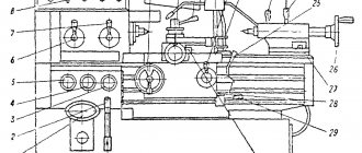
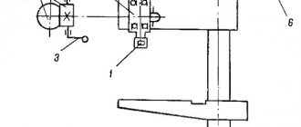
Location of the components of the drilling machine 2A150
Location of the components of the drilling machine 2a150
List of components of the drilling machine 2A150
- plate;
- table;
- spindle;
- gearbox;
- spindle head;
- electric motor;
- handwheel for manual spindle feed;
- bed;
- handle for vertical movement of the table.
A box-shaped column 8 is mounted on the foundation slab 1. In its upper part there is a spindle head 5, which carries an electric motor 6 and a spindle 3 with a tool. A spindle head 4 is installed on the vertical guides of the column, inside which there is a feed mechanism that carries out the vertical movement of the spindle. The spindle can be raised and lowered mechanically or manually, using the steering wheel 7. To install and secure the device with workpieces being processed, there is a table 2. It is installed at different heights, depending on the size of the workpieces.
Content
| 1. Introduction | 3 |
| 2. General information | 4 |
| 3. Vertical drilling machine 2A150 description | 6 |
| 4. Kinematic diagram | 7 |
| 5. Drive automation. Kinematic diagram | 13 |
| 6. Electrical diagram of the modernized machine | 15 |
| 7. Conclusion | 16 |
| 8. Bibliography | 17 |
What are we going to flash with?
There are two firmware platforms: Stick and Hilink. The former interact with the modem through a special software client, for example Megafon Internet or MTS Connect Manager. The main disadvantage of Stick firmware is the speed limit of 20-30 MB/s, and the client itself is often slow, either the modem does not see it, or the Internet will fall off at the wrong moment. If you plan to connect a usb modem to the router, then stick is not the best option, since the router may not recognize the modem, which will ultimately lead to endless dancing with a tambourine in search of a solution.
The latter make a kind of router out of a modem, which is accessed via a web interface (device IP address). Hilink has no speed restrictions and easily synchronizes with any router; for example, even an unupdated Zyxel router immediately recognizes the modem out of the box. Hilink has more flexible settings and is more reliable than stick, so the conclusion is obvious.
Flashing and Unblocking!
1. Disable all antiviruses, connect the usb modem to the computer and install the native client application, along with it the native drivers will be installed, this is necessary for the computer to recognize the modem. (If drivers and software are already installed, skip this step).
I will flash the M150-2 megaphone modem with e3372h firmware, if your modem is different, just follow my instructions and do everything by analogy.
2. Download and unpack the archive with the necessary files (I indicated the link above). First of all, we are interested in the DC Unlocker program - a terminal program, with its help we will find out all the necessary information on our modem using AT commands.
We launch the program (the USB modem must be connected), click on the “Magnifying Glass” icon to identify the modem. The terminal should provide the following required information.
It is necessary to record the following data, which will be useful to us in the future: Firmware version and IMEI.
By the way, by the firmware version we determine which firmware platform is currently installed. If in the first value there is a unit after the two, then it is a stick, but rather than after the two there is a 2 - Hilink.
As you can see, my firmware is e3372h.
2.1. Lucky ones. After identifying the modem through dc unlocker, we might have some lucky ones who can unlock the modem for all SIM cards at once using the at command. I’ll explain what the point is, the fact is that E3372h or E3372s modems with an old firmware version below 2_.200, starting with the following numbers 2_.180, have support for at commands by default.
If the firmware version is 2_.200.07 and higher, then we will have to flash the modem in any case, since our firmware does not support AT unlock commands, my modem fits this description, so we move on.
3. During the firmware installation, the program may request a password; to calculate it, you must use the application from the Huaweicalc archive. Enter the IMEI of the modem, click “Calc” and save the Flash code - it is the password.
4. Before flashing, you need to remove all operator software under frequent
Control Panel → Uninstall Programs → uninstall all operator software under frequent → restart the computer, this is extremely IMPORTANT! AFTER BOOTING YOUR COMPUTER, DISABLE ALL ANTI-VIRUSES AGAIN!
5. Disable the modem; there are three drivers in the archive with the files. We install them one by one. THE MODEM MUST BE DISCONNECTED! After installing the drivers, connect the modem.
6. I remind you that at the moment I am flashing a modem - e3372h, for e3372s the description will be given below, but you can view the flashing principle; it will not differ much from yours.
Now we need to understand which files are suitable for sewing a particular firmware version. We turn again to the firmware version of the usb modem and compare it with the following description.
In my case, the modem firmware version 21.200.07.01.209 is lower than 2_.200.15.__.__, which means I’m sewing according to the instructions from the first rectangle.
I find the required firmware, unpack it and install it. After updating the firmware, new drivers will be automatically installed and the computer will detect the new device.
7. The next step is to flash the Web interface of my Hilink modem with firmware, you will also find it in the archive.
We open and install WEBUI, after which we enter the IP address 192.168.8.1 in the search bar of the browser and get into the modem management interface. Now all we have to do is unlock the modem for all operators.
8. Open DC Unlocker, press the magnifying glass, as soon as the modem is identified, enter the AT command: at^nvwrex=8268,0,12,1,0,0,0,2,0,0,0,a,0,0,0 press enter. OK – the modem is unlocked.
When you subsequently identify the modem in DC Unlocker, a message will appear with the line: SIM Lock status – unlocked, this means that our modem works with all SIM cards.
Electrical equipment of machine 2a150
The electrical equipment of the machine includes:
- Asynchronous squirrel-cage electric motor for tool rotation and working feed;
- Electric cooling pump;
- Starting and protective equipment built into a column niche or electrical cabinet;
- Command equipment that controls turning on, reversing and stopping the spindle motor. This equipment is located on the spindle head of the machine on the left;
- Switching wires running mainly through the internal cavities of the column.
The machine can perform drilling with manual or automatic feed cut-off, as well as thread cutting with manual spindle reversal. The spindle is also retracted manually.
The electrical circuit provides protection against short circuits by fuses and overloads by thermal relays. Zero protection is provided by block contacts and starter coils.
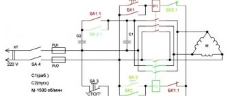
Description of the electrical circuit
Electrical diagram of drilling machine 2a150
List of elements of drilling machine 2a150
List of elements of drilling machine 2a150
- When the handle is turned to the “Right” position using the CL magnetic starter, the power circuit is broken and the GB magnetic starter circuit is turned on, the engine rotates to the right.
- When the handle is turned to the “Left” position using the magnetic starter of the gearbox, the power circuit is broken and the circuit of the magnetic starter of the gearbox is turned on, the engine rotates to the left.
Automation of table feed drive
In order for the table to move automatically, we install a reversible electric motor D2. The movement from the ED shaft is transmitted to the lead screw through a V-belt drive. The table moves from the final position KB2 to the final position KB1. When the engine reverses, the table moves backward from KV1 to KV2.
Fig. 7 Kinematic diagram of a machine with automatic table feed
Modem unlocking options
To begin this work, you need to “walk” the World Wide Web in order to find in its vast expanses Internet resources that offer their visitors various versions of encoding codes, depending on the following parameters - IMEI (indicated on the inside of the device cover), USB model device. Then we work according to the following scheme:
- Launch the browser;
- Enter the appropriate request;
- Opens an Internet resource;
- Enter the model number and IMEI code;
- We are waiting for the combination that removes restrictions from the mobile device;
- We copy this peculiar antidote;
- We open the USB device, insert a SIM card from a “foreign” operator into the device and “write” the previously received digital combination in the field that opens;
- Let's start using a mobile device.
The main disadvantage of this scheme is that the “MegaFon SIM card MTS modem” chain can be paid. In other words, the user often has to pay for a combination that removes restrictions from the wireless device. In addition, quite often such services only have an English version and, accordingly, require payment in foreign currency, and not in domestic rubles.
An alternative to the first option would be specialized forums. On these sites you can get maximum information on unlocking all existing Internet devices. However, this will require 4g modem firmware (version). This version, along with the IMEI and USB device model, is required to create a request.
You will have to wait for a code answer to unlock, and the waiting time can last for hours. But you won’t have to pay for a combination that removes all restrictions on the use of SIM cards from the modem. The main problem with this option is that not all Internet users will be able to independently determine the firmware version.
The third option, which opens the encrypted unlock code for the MegaFon modem, will require some effort and cash injections from the user. Paid software called DC-Unlocker can work with almost all existing wireless USB modems, “opening” them without information about the model, IMEI and firmware version. The main thing is to download unlock on the official Internet platform. And the activated program itself will determine the necessary parameters and offer to pay for a combination of numbers so that the unlocking for all operators is successfully carried out. Payment is made with credits purchased for eurocurrency on the Internet portal of the developer of this useful software. The cost of the operation is indicated in a special section of this website.
Let us recall the action plan:
- Download from the official resource and install DC-Unlocker on your USB device;
- Register and log in to the official developer portal;
- We pay for the service;
- Enter the received data (login and password) into the program window;
- Turn on the modem;
- Click on the “Unblock” button.
If everything was done correctly, then within a few seconds it will be unlocked for all operators of your USB device. Service center employees can use unlimited tariffs, but for a single case this option is not an option due to the high cost.
More advanced users will be able to unlock the MegaFon 4g m150 modem and other USB devices from HUAWEI absolutely free. This can be done using software called Unlock code calculator. This Internet application helps you quickly and without any payment unlock a USB device for all existing SIM cards from Tele2 and all other domestic companies that provide customers with wireless access to the World Wide Web.
The algorithm of actions for this option is as follows:
- We search for, download and install the application on your gadget;
- We launch the utility by left-clicking on the key called “”;
- We get two combinations (“v1 code”, “v2 code” and “v201 code”);
- We enter combinations of numbers one by one into the program window (one of the combinations will open the program);
- We work with an unlocked USB device.
Electrical diagram of the modernized machine
Fig. 8 Electrical circuit of the modernized
2A150
Main elements of the circuit:
· D1, D2 – drive motors with a short-circuited (short-circuited) rotor of the spindle and table.
· KSHL, KShP – spindle contactors of left and right rotation.
· Tr, LO – transformer and local lighting lamp
BB, VO – input switch, lighting switch
· KT – ring current collector, for ESN of moving parts of electrical equipment
· PR1-3 – fuses, designed to protect electrical networks from overloads and short circuits
· RT1-2 – thermal relay, designed to protect electric motors from overload
· K1-2 – table contactors, for moving in the direction of top and bottom
· VK1-3 – switches (buttons)
KV1-2 – final position of the button
The operation of the circuit is as follows: when voltage is applied, circuit BK1 is closed. We press the button VK2 - the table begins to rise up to the final position of KV1, stops, and the workpiece is processed. After the operation is completed, press the BK3 button, the table begins to lower down to the final position of KV2.
Adjustment and setup of drilling machine 2A150
Usually, after installing the machine at the workplace, depreservation, filling with oil and lubricant, connecting to the electrical network, checking operation at all speeds and feeds, it does not require any adjustment.
Setting up the machine consists of installing the table and spindle headstock in the positions required for operation and clamping the spindle headstock wedge, as well as setting the required speeds and feeds. When raising the spindle head to the position required for work, the gear shift handles should be in position “B”.
The drilling depth is set using the cam as follows. By rotating the steering wheel toward you, the drill is brought into contact with the workpiece, and the edge of the cam 24 (see figure) is installed against the division of the dial corresponding to the drilling depth. Then the cam screw is tightened. In this case, the division on the dial corresponds to the full drilling depth, including the conical part of the drill.
Changing the direction of rotation of the spindle is done with handle 6. The knurled cap 18, located in the center of the steering wheel, serves to turn off the mechanical feed if it is necessary to work with the feed manually. To do this, the cap must be moved along the axis away from itself until it stops.
Using a screw and a spring, the safety clutch is adjusted to self-shutdown at a feed force 10% higher than the nominal one, that is, at 2750 kgf.
The belt tension is adjusted by moving a special bracket with an electric motor installed on it, as indicated in the description of the gearbox design. The machine mechanisms allow a feed force of 2500 kgf, and cutting modes must be selected accordingly.
Switching speeds and feeds on the go is not allowed; it can only be done after stopping the electric motor.
The spindle bearing clearances are adjusted by tightening the nut above the top spindle bearing. The adjustment is made through a window located on the front wall of the spindle head, which is then closed with a lid. To make the adjustment, you need to turn the spindle so that the adjusting nut screw is in the window, and then, loosening the screw, tighten the nut and tighten it again.
Brief description of the design and operation of individual components of the 2A150 machine
The machine model 2A150 consists of the following components:
- gearbox;
- gearbox;
- feed mechanism;
- spindle;
- column, table, slab;
- cooling system;
- electrical equipment.
A column is installed on the foundation slab, and the gearbox is mounted on its upper plane. The table and spindle head, in which the feed box and feed mechanism are mounted, can be moved manually along the column guides.
Gearbox
Drilling machine gearbox 2a150
The gearbox housing (Fig. 6) is a solid cast iron, through the side windows of which the gears are mounted. The box communicates to the spindle twelve different speeds, which are obtained by moving two blocks of gears 1 and 2, installed sequentially by two handles 6 and 7 to the corresponding position of the speed table. Handles 6 and 7 are located on the left gearbox cover.
The output shaft 5 of the gearbox is a hollow sleeve, through the spline hole of which rotation is transmitted to the machine spindle.
The gearbox is driven by a vertically located electric motor through a V-belt drive. The electric motor is mounted on a special bracket, which can be moved along the axis of the box to ensure appropriate belt tension. The bracket is clamped with four bolts 3 and two strips sitting on a special screw 4.
The entire gearbox mechanism is lubricated by a special pump installed inside the gearbox.
Gearbox
Feed box for drilling machine 2a150
The feed box (Fig. 7) is installed in the mechanical feed headstock housing on the left cover. It is possible to disassemble the feed box independently of other machine components. The feed box is driven from the splined end of the spindle through a gear located in the upper part of the spindle head.
The feed box provides nine different spindle feeds by moving two blocks of gears 1 and 2. The spindle is switched on to a specific feed, corresponding to the feed rate table, by turning two handles 3 and 4 on the left spindle head cover. The feed box is lubricated by an independent oil pump mounted on the lower plane of the feed box.
Feed mechanism
Feed mechanism of drilling machine 2a150
The feed mechanism (Fig. is driven by the feed box through the cam clutch 3, which serves both to turn off the mechanical feed from the cam 24 installed on the limb 21, and as a safety device in case of overload. Using screw 1 and spring 2, the clutch is adjusted to self-switching off at a feed force 10% higher than the nominal one, that is, at 2750 kgf. The spring also ensures precise switching off of the feed when clutch 3 moves from the cam 24 on the dial. The mechanical feed can be turned off at any time by turning off clutch 3 sitting on the worm shaft 22 , handle 5 or turning the steering wheel 4 away from you.
To adjust the drilling depth, the end of the drill is brought into manual contact with the workpiece, and the edge of the cam 24 is aligned with the division of the dial 21, corresponding to the full drilling depth, including the conical part of the drill sharpening.
The operating principle of the feed mechanism is as follows. When the steering wheel 4 rotates toward itself, the coupling 7 connected to it rotates 20° relative to the shaft (the angle of 20° is limited by the slot on the coupling and the pin 8). In this case, the teeth of the coupling 7, thanks to the bevel present on them, shift the cage 9 in the axial direction and, entering the end face of the teeth of the cage, fix this displacement. A double-sided ratchet disk 10 is mounted on the holder, connected to the holder by spring pawls 11.
When the cage is displaced, the teeth of the disk engage with the teeth of the second disk 12, mounted on the worm wheel 13. Since the chain is closed by the ends of the teeth of the coupling 7 and cage 9, the rotation of the worm wheel is transmitted to the shaft 14.
With further rotation of the steering wheel 4, already with the feed switched on, the dogs 11 slip over the teeth of the inner side of the disk 10 and thus the mechanical feed is manually advanced. The feed is switched off manually by the steering wheel 4 by turning it in the opposite direction by 20° relative to the shaft 14. The teeth of the coupling 7 become opposite the depressions of the holder 9. The holder 9, due to the axial force arising due to the inclination of the teeth of the disks 10 and 12 and under the action of a special spring 15, is shifted to the right and disengages the disks. Mechanical feed stops.
The feed mechanism allows the spindle to be fed manually with a steering wheel directly through the rack and pinion gear on the horizontal shaft 14 and the spindle sleeve 17, for which it is necessary to turn off the mechanical feed with the steering wheel 4, and then move the cap 18 along the axis of the horizontal shaft 14 away from you. The latch 19 present in the cap 18 will take a position between the slot of the coupling 7 and the pin 8. Thus, the rotation of the steering wheel 4 is transmitted directly to the horizontal shaft.
For boring and trimming, it is possible to use fine feed manually, which is carried out when the cam clutch 3 is turned off through the conical pair 25 and 26. This pair is turned on when the fine manual feed handwheel 27 with the bevel gear 25 moves along the axis away from you, while the steering wheel 4 is located in mechanical feed position.
Since when the dial cam feed is turned off through clutch 5, the horizontal shaft 14 is not released, the rotating tool does not move away from the part and cleans the plane being processed, which is especially important during scoring work.
Thanks to the presence of a manually controlled electric reverse, it is possible to cut threads by manually approaching and retracting the tap. The permissible number of electric motor reverse strokes is no more than 30 per hour. When cutting threads, a safety chuck should be used.
The bearings of the worm pair of the feed mechanism are lubricated with oil located in the niche of the spindle head housing. The remaining supports and components of the feed mechanism are lubricated from a special pump. The spindle head can be easily moved along the column guides manually using a crank handle, thanks to the presence of worm and rack pairs. If it is necessary to move the spindle head along the guides, the spindle head wedge must first be pressed out. Work on the machine should be carried out after tightening all the bolts of the spindle head wedge.
Spindle
Drilling machine spindle 2a150
Spindle 1 (Fig. 9) rotates in ball bearings. The axial feed force is perceived by a thrust bearing mounted in the spindle sleeve at the lower spindle support. Bearings 2 are adjusted by tightening the nut located above the upper spindle support through the window in the front part of the spindle head.
The spindle bearings are lubricated with an oiler through the windows on the frontal part of the spindle head once per shift.
Chain 5, connected at one end to the spindle sleeve 4, passes through the rollers into the column and carries a load at its second end, which is the counterweight of the spindle sleeve.
Cooling system
To supply coolant to the tool, an electric pump mounted on the foundation plate is used. The pump pumps the emulsion from a reservoir in the plate, made in the form of labyrinth chambers to filter the liquid entering the instrument. The emulsion is supplied through a flexible hose with a tap to regulate the flow. The spent emulsion, flowing back into the tank, is cleared of chips, passing through the table mesh and the labyrinth chambers of the stove, and gets cleaned to the electric pump. At least once a month, it is necessary to clean the sump of the foundation slab from the dirt settled in it through the slab cover.
Types of modem firmware
Also, you need to remember that there are two fundamentally different types of firmware:
- HiLink
- Stick
I'll briefly tell you how they differ.
Stick - firmware
- The modem is controlled by Windows OS.
- Access to the Internet is carried out through the so-called dashboard, i.e. special program for Internet access
- Modems from MTS and Megafon are supplied with this type of firmware.
- Stick firmware version numbers always start with 21 - for example, 21.285.01.02.143
HiLink firmware
- Modems with HiLink firmware operate in router mode. Those. There is no need to install any programs.
- The modem is configured through a special Web interface. In general, everything is the same as in ordinary routers. There is no need to log into the program from the modem every time and press “connect”. Everything is simpler - plug the modem into the computer, and the Internet starts. No hassles.
- Modems from Beeline, as well as iota, are supplied with this type of firmware.
- Hilink firmware version numbers always start with 22 - for example, 22.286.03.00.00.
Benefits of HiLink
I will flash it in HiLink, because, firstly, Stick has speed limits of 20-30 Mbit, and secondly, HiLink is easier to connect to a home router. Well, thirdly, this type of firmware is more modern and convenient.
Of course, with the new firmware the modem can be configured for SIM cards of any operators.
Flashing the Megafon modem
Paid methods for replacing firmware
Megafon modem firmware is performed in the following ways:
Through online services. We classified them in the paid category because a large number of them actually provide services for money. How it works? You indicate the device manufacturer, IMEI number (it is indicated on the back of the case), and the service looks for the unlock code.
100% Method for unlocking USB modem Megafon e173u-1 or e173
After you receive it, you should launch the Megafon Internet program on your computer (first connect a modem to it, but without a SIM card) and enter the specified code. After this, the device will be reflashed, and you can insert any card from other operators into it.
DC-Unlocker application. Before downloading a program that is available on a separate website of the same name, check whether it is suitable for your device. If yes, install the service and run it. After that, you should select the language, indicate the manufacturer of the network equipment and the model - e173 or another. If you do not know this data, then leave the automatic detection.
Then do the following:
- Click on the icon with a magnifying glass, after which you will find out whether the modem is locked and how many attempts are left to unlock it.
Note. On all Beeline devices, by default, 10 attempts are given to remove the lock. If you get a lower number, it means that you have already tried to reflash the equipment before.
- Return again to the site where you downloaded the program, select the Buy Credits menu - here you will have to pay for the unlocking service and at the same time register on the portal.
- To find out how many “credits” you need to buy, click on the website “How much do I need?”
- After payment, a window will appear in front of you indicating your login and password in the program.
- Transfer the received data to DC-Unlocker, “Server” tab.
- Next, select the “Unlock” section.
- Click Run.
- After some time, a message indicating the successful completion of the operation will appear in the application window.
Free unlock options
In principle, they are worth trying first, but if such methods do not help, you will have to turn to paid options.
So, you can reflash the Megafon modem for any SIM card for free like this:
- Using specialized forums. For example, the most popular forum on this topic is 4pda. If you register and ask a question about flashing in the appropriate topic, specify the modem parameters correctly, they will probably find the unlock code for your device. It is best to indicate the maximum useful information - IMEI, model - e173 or another, firmware version.
- If you have a device from the HUAWEI brand, you can find out the required code through the Unlock code calculator program - just run it and you will receive v1 and v2 codes, one of them will certainly be suitable for flashing the firmware of your model.
In both cases, the resulting combinations of numbers should be used in the Megafon Internet application.