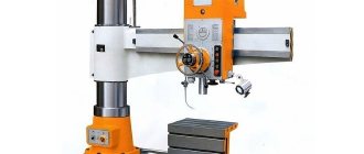
Equipment design
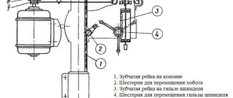
The radial drilling machine model 2M55 consists of:
- sleeves (traverses);
- base slabs;
- cooling systems;
- gearboxes;
- drilling heads;
- a device that provides fixation of the drilling head;
- hydraulic equipment stations;
- panels of hydraulic equipment, hydraulic communications, hydraulic preselector and its drive;
- main hydraulic cylinder;
- gearbox;
- a device that ensures lifting of the traverse;
- worm shaft;
- current collector;
- columns;
- electrical equipment heads, sleeves and columns;
- spindle unit;
- feed boxes;
- friction clutch;
- a mechanism that ensures manual movement of the working head;
- counterweight device;
- control systems;
- devices for turning on and controlling feeds;
- pumping mechanism.
Machine design 2M55
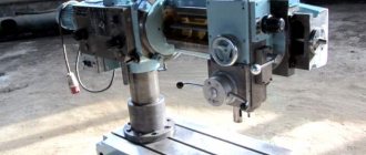
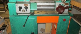
The function of the base of the radial drilling machine is performed by a massive plate. A plinth is mounted on it for installing a rotating column. On a column made of steel there is a sleeve with a working head, the movement of which is ensured by a special mechanism.
Access to adjust the pressure in the hydraulic system is from the rear of the machine
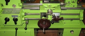
The working head is a separate mechanism that includes several structural elements: a spindle assembly, a counterweight, a feed and speed box. This unit moves along the traverse manually, and is fixed in the required position using a special clamping mechanism.
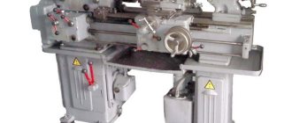
Removed machine head
Technical properties
The technical characteristics of this model are as follows:
- Using this equipment, you can drill a maximum hole with a diameter of 5 cm;
- the accuracy category of the unit is N - normal;
- the sleeve with the drilling head can rotate 360 degrees;
- the traverse is capable of moving in the vertical direction to a distance of 75 cm;
- the edge of the spindle can be placed relative to the desktop at a distance from 45 cm to 1.6 m;
- the desktop has dimensions of 2.555x1 m;
- the weight of the machine is 4.7 tons;
- the minimum possible distance from the spindle assembly to the column is 375 mm, the maximum is 1600 mm;
- with the help of a traverse, the head can move a distance of 1.225 m;
- the spindle can move in the vertical direction to a distance of 40 cm;
- This model is equipped with six electric motors. The main one, responsible for performing basic operations, has a power of 4.5 kW.
Taking into account all these characteristics, the 2M55 model was able to gain such popularity among manufacturing enterprises of various types.
Electrical equipment
On the 2M55 machine, the electrical diagram shows the control of the working parts. The electrical circuit diagram is shown in the figure.
Electrical diagram of the 2M55 machine
- Safety of work on the machine is ensured by locks.
- If the control device is in the on state, then power will not be supplied to the engine until the control handle is set to the neutral position.
- Switching gears is impossible while the hydraulic preselector is operating. The signal is not supplied to the spool coil.
- The movement of the hose along the column is limited by two limit switches.
By supplying power to the electrical circuit, the main engine and the hydraulic motor are turned on, and the machine goes into setup mode.
Clamping and release of the drilling unit and column are hydraulic. The electrical circuit controls the hydraulic spool coils. The possibility of separate spinning of the drilling unit is organized.
You can only rotate the sleeve and move the drilling head manually by pressing the release button. The movement of the hose along the column is carried out by a separate M2 engine.
The circuit provides a preselective preset of spindle rotation speeds and working feeds. These operations are performed while the machine is running. At the end of processing, the signal from the relay is sent to the M5 engine. It moves the switching mechanism until the positions of switch B11 are matched with switch B13. After this, switching to the specified modes occurs.
The spindle has reverse rotation.
The load on the spindle motor is monitored using an ammeter IP1.
Controls
For the 2M55 machine, the operating manual describes how to control the machine.
Machine controls 2M55
The figure shows the following controls located on the drill head:
- accelerated spindle approach, connection of working feed – 5;
- drilling depth setting – 6;
- feed blocking during thread cutting – 7;
- latch for regulating the lowering of the coolant valve – 8;
- spinning the drill head – 9;
- spinning the column together with the drilling head – 10;
- column clamp together with drilling head – 11;
- connection between the dial and the feed mechanism -12;
- dial fine adjustment -13;
- ammeter (load indicator) – 14;
- counterweight spring tension regulator – 15;
- pre-dial indicator – 16;
- sleeve rise – 17;
- spindle shutdown – 18;
- pre-dial handle – 19;
- main engine start – 20;
- lowering the sleeve – 21;
- feed preset – 22;
- stop button – 23;
- reverse – 25;
- local lighting – 26;
- turning on mechanical feed – 29;
- precise manual feed – 30;
- coolant valve – 31;
- flywheel for drilling unit movement - 32.
2M55 2M57 2A554
Machine 2M55
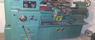
The 2M55 radial drilling machine is designed for drilling, reaming, countersinking, reaming, boring holes, tapping threads, trimming ends with a cutter, as well as performing other similar operations when processing various body parts.
Spare parts for the 2M55 machine
| № | Name | Marking |
| 1. | Bimetallic nut | 2М55.00.22.010 |
| 2. | Friction clutch control master cylinder | 2М55.50.66.000 |
| 3. | Worm wheel | 2M55.50.27.015 |
| 4. | coupling | 2M55.50.27.033 |
| 5. | Hydraulic preselector drive | 2М55.50.46.000 |
| 6. | Brake ring |
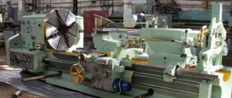
Machine 2M57
The radial drilling machine 2M57 is designed for drilling, reaming, countersinking, reaming, and threading. It is used in single and serial production.
| № | Name | Marking |
| 1. | Friction disc | 2M57.75.15.033 |
| 2. | Friction disc | 2M57.75.15.042 |
| 3. | Friction disc | 2М57.75.15.047 |
| 4. | Friction disc | 2M57.75.15.081 |
| 5. | Speed selector | 2М57.75.49.000 |
| 6. | Counterweight assembly | |
| 7. | Brake ring | |
| 8. | Head moving unit |
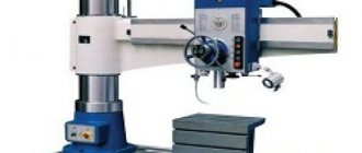
Machine 2A554
The radial drilling machine model 2A554 is used to process holes for medium- and large-sized parts. This machine provides the ability to carry out types of work such as drilling, reaming, countersinking, threading and end trimming. Radial drilling equipment of the 2A554 model is actively used both in single and in small-scale and mass production.
| № | Name | Marking |
| 1. | Worm wheel | 2A554.50.26.082 |
| 2. | Gearbox | 2A554.50.17.000 |
| 3. | Gearbox assembly | 2A554.50.16.000 |
| 4. | Feed activation mechanism assembly | 2A554.50.26.000SB |
| 5. | Feed switching mechanism | 2А554.50.25.000 |
| 6. | Spindle |
Wearing parts for machine tools
| № | Name | Marking |
| 1. | Hydro preselector | 2A554.50.45.000 |
| 2. | Hydro preselector | 2A576.81.46.000 |
| 3. | Hydro preselector | 2М55.50.45.000 |
| 4. | Friction disc (set) | 2A554 |
| 5. | Friction disc (set) | 2A576 |
| 6. | Friction disc (set) | 2M55 |
| 7. | Friction disc (set) | 2M57 |
| 8. | Friction disc (set) d=140mm | 2M58 |
| 9. | Friction clutch | 2576.81.15.000 |
| 10. | Friction clutch | 2576.50.15.000 |
| 11. | Counterweight spring | 2576.81.39.010 |
| 12. | Counterweight spring | 2M55.50.56.020 |
| 13. | Counterweight spring | 2М57.6112 (2М57.75.37.010) |
| 14. | Spindle (6 spline fit) | 2М55.50.55.000 |
Purpose of the equipment
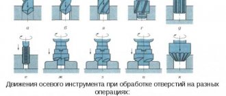
This model performs operations related to the processing of holes. Using various tools, holes are processed using: drilling and reaming, countersinking and counterbore, and then reaming. Also on the machine, the ends are processed by trimming and threads are cut in the body of the part.
Radial drilling machines 2M55, the equipment of which can be expanded with specialized devices, perform operations of turning grooves inside holes, cutting holes on a metal sheet, and can also carry out high-speed processing.
The main advantage of radial drilling machines is the absence of movement of the workpiece during processing. Heavy or large parts are installed once, and processing is carried out by moving the tool over the surface of the part. This method reduces the loss of time for reinstallation and eliminates the inconvenience of turning.
Design of radial drilling machine model 2A554
The elements that make up the design of the 2A554 radial drilling machine are:
- a foundation plate that serves both as the base of the machine and as a base for placing the workpiece being processed (to ensure fixation of the latter, there are several T-shaped grooves on the upper surface of such a plate);
- a column that ensures rotation of the traverse and its movement along a vertical axis (for easy, smooth and accurate rotation, a bearing unit is mounted at the base of the column);
- traverse mounted on a column;
- a working head that moves in a horizontal plane along the traverse guides;
- a mechanism that ensures rotation of the traverse and its fixation in a certain position;
- main electric motor, drive mechanism, feed control box.
Main components of the machine (click to enlarge)
The controls are located on the side of the drilling head of the 2A554 radial drilling machine, which makes working on it convenient and efficient. The operator sets the modes before starting processing, which makes it possible to increase not only its productivity, but also the accuracy of execution.
Purpose of controls (click to enlarge)
Machine illustrations and specifications
For your reference, diagrams and drawings of the main components of the machine are provided. Using them, you can understand what structural elements it consists of.
Specification for the machine diagram:
Control drawing:
Republished by Blog Post Promoter
Setting up and setting up a radial drilling machine 2N55
The workpiece, depending on its overall dimensions, is mounted on a plate or on the machine table. The fastening of the part must be reliable, since during drilling the part can turn and cause injury to the worker and damage to the machine.
In accordance with the operation performed on the machine, auxiliary and cutting tools are selected and installed in the spindle. When working sequentially with several tools, use a quick-change chuck. In case of thread cutting, a safety cartridge must be installed.
When using heavy tools, the counterweight spring should be adjusted. The counterweight is adjusted in the lower position of the spindle.
The sleeve is installed at such a height that processing is carried out with the spindle quill minimally extended.
When choosing cutting modes, you should keep in mind the dynamic parameters of the machine (see section “Brief instructions for using machines”).
However, the choice of modes that exceed the specified parameters will not lead to the destruction of machine parts, since its power units are equipped with safety devices that protect the machine mechanisms from overload. When the fuses trip, you need to reduce the modes.
The set of speeds and feeds is carried out as follows:
Case 1 – the spindle does not work, the friction clutch control handle is in the middle fixed position. Turn the handle for setting speeds or feeds until the desired number on the handle aligns with the index rod. At the same time, a signal lamp on the remote control lights up with the inscription “set of modes”. After the lamp goes out, turn on the spindle using the friction clutch control handle.
The direction of spindle rotation corresponding to the position of the handle is indicated by an arrow on the plate next to the handle.
The mechanical feed is activated by moving handle 19 (see Fig. 15) up. Before turning on the friction clutch control handle, handle 19 must be lowered.
Case 2 - the spindle is working, the friction clutch control handle is in one of the extreme positions.” Turn the dial handle to the desired position, after the “mode set” signal light goes out, move the friction clutch control handle to the middle fixed position, then turn on the control handle again friction clutch,
During operation, the mechanical feed can be turned on and off using handles 25 (see Fig. 16). Turning on the mechanical feed with handles 25, move them away from you.
Cooling system
A container for coolant is placed in the voids of the slab. The coolant is supplied to the cutting area, to the tip, by a pump through a hose. Depending on the dimensions of the part, you can control the height of the tip.
In 2M55, the amount of coolant is poured depending on the productivity of the pump. Its productivity is 22 l/min.
Gorbyl we use production waste for good: types, production, application, calculation of parameters
Machine cooling system
List of cooling system components:
- lid closing the container -1;
- pump assembly – 2;
- hose – 3;
- tee – 4;
- lowering regulator – 5;
- bar – 6;
- tip – 7;
- swivel joint – 8;
- grid – 9.
Radial drilling equipment 2M55 with CNC
To increase the productivity of units of this brand and improve the quality of processing of parts at metallurgical enterprises and machine-building plants, CNC can be used in addition to them. In CNC modifications (for example, a 2M55F2 machine), the software is usually used for movement along three axes, the tool number and processing mode parameters. In this case, the workpiece can be installed on a table-slab or on the foundation of the unit. The operator changes tools manually.
To ensure uninterrupted operation of the 2M55 CNC radial drilling machine, a rack for 18 tools is usually installed next to it. Each cell of the latter is equipped with a light indicating the order of installation in the spindle. Switches are also mounted here to control the order in which the tools are used.
Horizontal drilling
This type of equipment is designed for horizontal processing of various parts and workpieces. The drilling unit is located at the end part relative to the structure, and also has a height shift function. For this purpose, the machine has vertically located guides.
The specificity of the operation of such models is the ability to process massive parts. To achieve this, the equipment design must include a relatively large work table. To securely fix the parts, it is recommended to use a magnetic base. Most often, horizontal drilling machines are used to complete large production lines.
Specifics of equipment operation:
- availability of devices for precise drill positioning;
- rotating mechanism of the desktop. With its help, the part is shifted, which increases the productivity of the complex;
- The drilling unit is designed for the maximum possible mechanical loads. This makes it possible to process parts made of special tool steels.
The main disadvantage of these models is their high cost. You should also consider the labor intensity of maintenance due to the complexity of the design.
Kinematic diagram of the radial drilling machine 2A53
Kinematic diagram of the radial drilling machine 2A53
Description of the kinematic diagram of the machine
The kinematic diagram of the machine (Fig. 9) consists of four kinematic chains:
- Spindle rotation circuit;
- Feed chain (vertical movement of the quill with the spindle in the drilling head);
- Chain of vertical movement of the sleeve along the chain along the column
- Chain of horizontal movement of the drilling head along the sleeve.
The spindle receives rotation from a two-speed electric motor 42, which, through a pair of gears 1 and 2, imparts rotation to shaft II of the gearbox (see Fig. 18).
On shaft II there are two friction clutches 43 and 44. When the upper clutch 43 is engaged, rotation is transmitted to shaft IV by gears 3 and 4, and when the lower clutch 44 is engaged - by gears 5, b and 7.
The presence of shaft III with idler gear 6 ensures a change in the direction of rotation of the spindle when switching clutches. The number of teeth of the indicated gears is selected in such a way that the number of spindle revolutions when the upper clutch is turned on is 1.41 times higher than when the lower clutch is turned off.
This allows the use of clutches not only to reverse the spindle, but also to change its rotation speed. Maintaining a constant direction of rotation of the spindle in this case is achieved by automatically reversing the electric motor 42.
A double gear block with three positions moves along the VI spindle sleeve. In the upper position, the block transmits rotation to the spindle through gears 4 and 13; on average - through gears 10 and 12; in the lower one, gear 12 is in mesh with gear 11. In this case, the spindle receives rotation from shaft IV through shaft V through gears 8, 9, 11 and 12.
Maintaining the direction of rotation of the spindle when the reversing shaft V is turned on is also ensured by automatic reversal of the drive motor.
Consequently, the spindle has 12 different rotation speeds ranging from 50 to 2240 rpm, obtained by varying the speed of the electric motor, shifting the friction clutch and the double gear unit acting as a triple unit.
By switching the friction clutch without correspondingly reversing the electric motor, you can get the same 12 spindle rotation speeds, but only in the opposite direction.
The feed box (see Fig. 23) receives rotation from the spindle through a permanent gearbox with gears: 14 and 15, 16 and 17, 18 and 19.
The last gear 19 is attached to shaft IX, along which a double gear block moves. This block transmits two rotation speeds to shaft X through gears 20 and 21 or 22 and 23.
A four-crown gear block moving along shaft XI imparts 8 speeds to this shaft through gears: 23 and 24, 25 and 26, 27 and 28 or 29 and 30. When the gear clutch 45 is engaged, the rotation from the feed box is transmitted to the shaft XII of the feed mechanism (see Fig. 24). Worm 31 sitting on this shaft. through the worm wheel 32, it imparts rotation to shaft XIII, the gear 33 of which is in mesh with the rack 48, cut into the spindle quills.
Thus, the quill with the spindle located in it receives 8 mechanical feed values per spindle revolution.
With clutch 45 turned off, you can use flywheel 46 to feed the spindle manually.
Rapid movement of the spindle is performed using handles 47.
The mechanism for the vertical movement of the sleeve (see Fig. 14) is driven by a separate electric motor 49. The rotational movement through gears 36 and 37, 38 and 39 is communicated to the screw 40, which, rotating in the nut 41 fixed in the sleeve, ensures the raising or lowering of the latter. Changing the direction of movement of the sleeve is done by reversing the electric motor 49 using a push-button station.
Manual movement of the drilling head along the guides of the sleeve is performed by rotating the handwheel 52 (see Fig. 25), which is mounted on roller XIV. located inside shaft XIII. Gear 34, sitting on roller XIV, is in mesh with gear 35, which is connected to a rack 51 mounted on the sleeve. When the handwheel 52 rotates, the gear 35 moves along the rack, moving the drilling head.
Performing drilling work on a machine
Rotation from the electric motor is transmitted to:
- elastic coupling that smoothes vibration;
- a clutch that allows you to engage the gear in “soft” mode;
- a gearbox with movable gear blocks (4 pcs.).
The presence of a ring gear in the gearbox allows for reverse rotation of the spindle. It turns on after the clutches stop. For every two forward speeds there is one reverse speed.
In double gear blocks, it is possible to move the slider so that there is no engagement in the third intermediate position. Then the operator can rotate by hand without much effort (there is no gearing, no need to rotate the gear blocks).
A feed clutch is used to move the spindle vertically up and down. A worm gear is used here: a worm wheel and a worm. They carry out the movement of the spindle quill in forward and reverse directions (changed by turning on the reverse motor).
Coarse and fine feeding of the tool is possible using handles and control wheels on the drilling column of the machine. During the production process, you can drill parts manually by rotating the handwheel. When you select the required feed on the control panel (the required spindle movement in mm/rev of the drill), the work is performed automatically. You need to set the required drilling depth.
When reversing the spindle feed motor, a dog-type safety clutch is used. If the maximum moving force increases, it is switched off. This technical solution allows you not to overload the tool (prevents its breakage) when drilling holes.
Operating procedure on the 2K52-I machine
Setup, adjustment and operating mode
After installing the machine, pay attention to its stability and, if necessary, secure the base (for heavy-duty operation). Clamping of the sleeve on the barrel and the drilling head on the carriage is carried out manually, therefore, before each change in the position of the sleeve and head, they should be wrung out, and after turning, a full clamp must be performed
Clamping of the sleeve on the barrel and the drilling head on the carriage is carried out manually, therefore, before each change in the position of the sleeve and head, they should be wrung out, and after turning, a full clamp must be performed.
Due to the design features of the 2K52-I machine (portable type), which is usually installed without rigid fastening, the cutting modes on it are assigned lower compared to stationary type machines.
The choice of cutting modes is made depending on the material being processed and the diameter of the cutting tool. The feed box handle is set to the position corresponding to the selected mechanical feed. Select the required rotation speed using two handles located on the front side of the barrel, in accordance with the plate.
ATTENTION! You can switch the rotation speed and feed rates only when the spindle is stopped. When drilling, pay attention to the correct sharpening of the drill, since processing with a tool with incorrect sharpening significantly increases the feed force and reduces the life of the spindle bearings
When drilling, pay attention to the correct sharpening of the drill, since processing with a tool with incorrect sharpening significantly increases the feed force and reduces the life of the spindle bearings. The required depth of processing is set and measured along the dial of the steering device using handles
The required depth of processing is set and measured along the dial of the steering device using handles.
Regulation
During the operation of the machine, there is a need to regulate its individual components to restore their normal operation. The design of the machine provides the ability to regulate individual elements, the parts of which wear out during operation.
The barrel clamp on the column is adjusted by turning nut 1 (see Fig. 12) to an angle corresponding to thread wear, and then locking nut 2.
The clamp is considered sufficient if the barrel does not rotate on the column under a force of 1000 N at the end of the sleeve.
The clamping of the carriage on the sleeve guides can be adjusted by turning the eccentric shaft acting on the sleeve 3 (see Fig. 14), rod B and clamp 7. The clamping of the carriage is considered sufficient if it cannot be moved from its place under a force of 2500 N.
If it is necessary to adjust the gap between the prismatic guides of the sleeve and the carriage, release the clamps of the eccentric axes I and II and turn these axes to set the required gap (up to 0.05 mm). In this case, the ease of movement of the carriage with the head along the sleeve should not be impaired. After completing the adjustment, tighten the eccentric axle clamps with the screws.
To facilitate the effort of moving the carriage along the sleeve guides, bearings are installed on it, with the help of which the carriage is suspended in relation to the sleeve guides. The adjustment is carried out by turning the torsion eccentric until a gap begins to appear between the front guide of the sleeve and the carriage.
Increased axial play of the spindle is eliminated by tightening the nut, access to which is possible after removing the spindle from the drilling head housing.
The safety clutch against overload in terms of axial force is adjusted using two nuts 5 (see Fig. 17), which tighten the spring 4. The nominal axial force is achieved by adjusting the modes, and under the modes specified in section 10.3, the clutch ensures the transmission of an axial force of 7500 ± 1000 N (no actuation - slipping of the cams of coupling half 2 relative to the cams of coupling half I - occurs).
Limit permissible operating modes
Material – steel 45, GOST 1050-74 Machining diameter – 25 mm Tool – drill 25 mm Tool – drill 25-3, GOST 10903-77
Spindle speed – 160 rpm Feed – 0.125 mm/rev Cutting speed – 14.2 m/min Spindle torque – 110±10 Nm Axial cutting force – 7500±1000 N
general information
The 2M55 radial drilling machine began to be produced at the Odessa Machine Tool Plant. Its mass production began in the second half of the twentieth century. Since that time, technical specifications and basic electricity. The layout of the machine has changed a little, but the principles by which it works remain completely the same.
It is not for nothing that we focus on the fact that the machine model 2M55 is of the radial drilling type. This point has a huge impact on the way he works. Yes and el. the scheme also changes significantly depending on the design of the machine. You just need to look at his passport to be convinced of this.
The fact is that standard machine models are practically stationary. That is, the spindle on them is in a fixed state. Of course, they can be successfully used for:
- drilling;
- boring;
- countersinking;
- thread cutting, etc.
Email the diagram and even the basic technical characteristics of the unit allow this. But standard machines also have their disadvantages. They consist of rather constrained spindle movements.
The base plate serves as the base of the 2m55 unit
That is, you can drill with it without problems, but if you need to process a heavy, durable workpiece with many necessary working areas, then troubles begin.
You will have to constantly move the part in a vice, shift it relative to the stationary spindle, which is extremely difficult and inconvenient. First of all, this inconvenience is associated with a simple loss of time.
After all, large parts themselves are heavy. To fix them again, it is necessary to unclench the vice, remove its fastening from the table (and the scheme of their fastening is most often based on tightly tightened bolts) and then remount it in a new position.
As you can see, the number of actions that are spent on the simplest work algorithm is quite large. A completely different situation occurs when a radial drilling machine is used, in particular model 2M55, 2M55F2, etc.
Advantages
The radial drilling machine has many advantages. They relate to both technical characteristics and many other parameters. To verify this, just look at the product data sheet.
The passport will provide you with all the necessary data, right down to the grade of metal that was used to create this or that element. Also included in the passport is a basic email address. machine diagram and its structure.
The 2M55 radial drilling machine itself differs from others in its ability to move the spindle head in several directions at once.
Electrical unit of the machine 2M55
First of all, the spindle can be moved by moving along the rack. It is mounted on a rail in a separate housing, along with the engine and all necessary equipment.
The lath itself is attached to the column, as the workers call it. The column is the main mounting frame for the machine and its motors, as well as the main mechanism for manipulation. The column can both lift the rail from one level to another and rotate it horizontally.
data-ad-client=»ca-pub-8514915293567855″ data-ad-slot=»5929285318″>
As a result, we have an extremely functional and at the same time powerful mechanism, whose electronics. the circuit allows it to be used for a wide variety of work applications.
The spindle can be adjusted by the rotation angle, lift height and specific coordinate on the frame. You can also adjust the speed of its rotation, the strength and even the direction of rotation.
At the same time, the 2M55 machine and its subsequent models 2M55F2 are equipped with an extremely comfortable and wide table or stand.
Machine model 2M55, model 1976
This table has an impressive area, which gives the worker some room for maneuver. By combining good spindle mobility of a radial drilling machine and a large table area, experienced craftsmen manage to increase the processing speed of complex parts several times.
Features of the 2M55F2 machine
The 2M55F2 machine is slightly different from its basic model. We will not describe all its subtleties and nuances; we will note only the most important ones.
But the main differences lie on the surface, and you can see them without even looking at the product passport. The fundamental difference between the 2M55 and 2M55F2 machines is the presence of CNC in the second model.
CNC is a numerical software module. Many modern machine tools are equipped with CNC modules as this allows for even greater performance improvement at the final stage.
A modern version of the 2M55 machine
Email The layout of the 2M55F2 machine also has differences, but the main nuances again relate to the presence of a software module.
CNC on the 2M55F2 machine can significantly reduce the presence of a person and the expenditure of his effort on processing the part. After all, he now only needs to configure the device, give it the correct coordinates and observe the work.
The machine itself will move the spindle to the desired location and begin processing.
The only problem with CNC is their high cost and the need to use precision measuring instruments, coordinate tables, etc. in the load.
This is interesting: Homemade sandblasting gun: device, instructions, video
Areas of application and technical features of the machine
The 2M55 machine, the design of which was developed in the famous Odessa design bureau "ARS", is used to perform such technological operations as:
- drilling and reaming holes;
- countersinking;
- deployment;
- boring pre-made holes;
- internal thread cutting;
- trimming the ends of parts, etc.
Due to the versatility of the radial drilling machine model 2M55, it is successfully used in enterprises that produce products in single, small and medium series, and in assembly shops of enterprises working in the field of heavy transport engineering. The technical capabilities of the machine allow it to be equipped with additional devices and tools, thanks to which this device can be used in large-scale production.
The massive base of the 2M55 machine allows you to place two tables and work with large parts
An important advantage of using the apparatus in question is that the workpiece remains stationary, and all movements are made by the spindle assembly with the cutting tool fixed in it. This design feature of the 2M55 model saves time and also eliminates the need to move large and heavy parts across the equipment workbench
Machine installation dimensions
The advantages of the radial drilling machine model 2M55 include the following features.
- There are no mechanisms in the upper part of the unit that require maintenance, which greatly simplifies the process of using the device.
- The column clamping, due to the use of a cone mechanism, is characterized by high rigidity, which makes processing at high speeds possible. Thanks to this characteristic, the stroke of the traverse along the column and the drilling head along the traverse increases, resulting in an increase in the volume of the working space.
- Thanks to the two-column layout of the 2M55 radial drilling machine and equipping the equipment traverse with rigid guides, high precision processing of workpieces is ensured.
- The high speed of movement of the hose along the column and the speed of its clamping significantly reduce the time required to perform auxiliary operations.
- The design of the machine guides, in the development of which innovative approaches were used, increases its maintainability and reduces maintenance time. Of particular importance are the following characteristics of the radial drilling machine model 2M55.
- The counterweight with which the spindle unit is equipped makes it possible to quickly adjust this unit depending on the weight of the tool used.
- Due to the special design, the machine column rotates very easily, as a result the operator expends a minimum of effort when performing such an operation.
- The machine guides do not require frequent scraping; planned measures are sufficient to restore their characteristics.
- The technical capabilities of the 2M55 radial drilling machine provide for automatic shutdown of the rotating tool when it has reached the required drilling depth.
- The column clamp, thanks to its special design, creates a significant braking torque, which increases the productivity of the device.
- The design of the 2M55 radial drilling machine has an electro-hydraulic preselective mechanism, controlled remotely and allowing you to pre-set the necessary drilling characteristics, as well as quickly change them during processing.
- The high rigidity of the 2M55 machine ensures that the spindle axis remains in its original position during operation.
Machine controls (click to enlarge)
Some distinctive features of the equipment
Studying the technical data sheet of this model, one can note some of its distinctive characteristics:
- The spindle of the unit is equipped with a counterweight. This allows the operator, when using tools with unusual weight, to adjust their operation without leaving his usual workplace,
- Having studied the passport of the drilling machine, it is clear that it has a unique structure. This allows you to use a minimum of physical force to rotate the columns,
- for efficient operation of the equipment, it does not require too frequent scraping of its guide elements,
- When the working tool reaches the required depth during drilling, its rotation stops. This is due to the presence of a special mechanism in the design of the machine,
- This model is characterized by high performance. This is possible thanks to the braking torque, which is generated by a specific clamping of the column,
- Having studied the equipment passport, it is clear that it is equipped with an electrohydraulic preselective mechanism. It can be controlled remotely and indicate the required drilling mode in advance, changing it if necessary at any appropriate moment,
- if the column is clamped, the spindle axis does not move. This is possible due to the fact that this drilling machine is highly rigid.
Drills, countersinks
Specifications
- Drilling diameter in steel 45 according to GOST 1050-38, mm 32
- Drilling diameter in cast iron SCH according to GOST 1412-89, mm 40
- Distance from the spindle axis to the guide column (overhang), mm 1000
- Weight of 2L53U tool, kg, max 5
- Spindle travel, mm max 325
- Drill head movement along the sleeve, mm, max 710
- Max vertical movement of the hose along the column, mm 6251
- Angle of max rotation of the sleeve around the axis of the column, degrees. 330
- Spindle speed limits, min-1 35.5 - 1400
- Number of spindle rotation stages 8
- Number of working feed stages 6
- Overall dimensions, mm LxWxH, mm 2500x1070x2840
- Weight, kg 3500
The lightweight radial drilling machine 2L53U is used for single, small-scale and mass production. The equipment is actively used in small procurement enterprises, workshops and factories. The mechanism is capable of performing such technological operations as:
- countersinking;
- drilling;
- reaming;
- thread cutting;
- deployment;
- cutting planes with a cutter.
Before purchasing a 2L53U machine, it is worth preparing a concrete base for installing the equipment. The layer height must be at least 40 cm.
Main parts and components of the machine:
- cast iron work table with a rotating design that can be rotated around its axis by +90 and -80 degrees manually;
- coolant supply system;
- feed switching device;
- a drilling head, in the body of which there is a gearbox and a feedbox, a device for switching the feed and controls;
- electrical equipment, wiring and electrical cabinet;
- a barrel on which a rotary table is mounted, which moves vertically and around the column 360 degrees;
- controls;
- mechanism for moving and clamping the drill head.
- a sleeve on which the drill head mechanism is located;
- a foundation slab on which a vertical cast iron column is located.
To prevent breakage of electrical wires, the rotation of the hose relative to the column is constrained by rigid stops. The movement of the barrel along the column is possible due to the reliable connection of the screw with the bracket. To prevent overheating of the working tool and rapid wear of the equipment, a coolant is built into the 2L53U design, which supplies liquid using a cooling pump.
To switch the speed and feed, the operator needs to operate the handle, which is located on the right side of the drill head. The safety clutch is located in such a way that a specialist can make the necessary adjustments without dismantling the components.
The industrial machine tool 2L53U is equipped with three electric motors, namely:
- for supplying coolant to the working area - 0.125 kW;
- table drive – 0.56 kW;
- spindle drive – 2.2 kW.
The 2L53U machine is reliably protected from overloads and short circuits using a fuse and a thermal relay. Unauthorized movement of the table is not allowed if the spin handle and limit switch are locked. In addition, there is a special braking device, which is controlled by an electromagnet. In order for the spring brake to work, the handle must be set to the neutral position, which automatically turns off the electromagnet. The braking system also operates automatically in the event of intentional or accidental power outages.
The 2L53U radial drilling machine allows the operator to perform processing of various levels of complexity. This is possible due to the wide range of spindle speeds and feeds. The big advantage is that the specialist, working at the machine, makes a minimum of physical effort with smaller drilling radii, which allows increasing the efficiency of the work process. All types of technological operations are carried out strictly with international quality standards.
To improve the mechanism, the following is mounted into the structure:
- protective screen for the drilling and cutting area;
- air cooling system for working equipment;
- swivel or standard cabinet.
This machine model is considered indispensable if the enterprise constantly needs to process metal parts. The equipment is quite easy to use and can easily act as an independent production unit.
Technical parameters and characteristics
Radial drilling machine 2M55, the technical characteristics of which reflect the following parameters:
- accuracy class – N according to GOST 8-71;
- maximum permissible drilling size: cast iron – 63 mm;
- steel – 50 mm;
- swing - 1600 mm;
Pinol:
- cone on the spindle for tool mounting - Morse 5 according to GOST 24644-81;
- number of switchable speeds – 21;
- setting speed range – min 20 min-1, max 2000 min-1;
- number of innings – 12;
- feed range – 0.056-2.5 mm/rev;
- feed force when cutting, max – 20000 N;
- torque - 7000 N•m.
Parameters of electrical elements:
- general network, current - three-phase alternating;
- electric motor power:
- main - 4000 W;
- sleeve drive - 2200 W;
- column clamp - 500 W;
- drill clamp – 500 W;
- coolant stations - 125 W;
- speed switching – 150 W;
- feed switching – 150 W;
Dimensions:
- Dimensions of the machine, LxWxH - 2545x1000x3315 mm;
- equipment weight - 4.1 tons.
Electrical equipment
On the 2M55 machine, the electrical diagram shows the control of the working parts. The important electrical circuit is provided in the figure.
Wiring diagram of the machine 2M55
- Working safety on the machine is ensured by interlocks.
- If the control device is in the on state, then power will not be supplied to the motor until the control knob is set to the neutral position.
- Switching speeds is impossible during the operating period of the hydraulic preselector. The signal is not supplied to the spool coil.
- The movement of the hose along the column is limited by 2 limit switches.
By supplying power to the electrical circuit, the main motor and hydraulic motor are turned on, and the machine goes into setup mode.
Clamping and release of the drilling unit and column are hydraulic. The electrical circuit controls the hydraulic spool coils. The possibility of separate spinning of the drilling unit is organized.
You can only rotate the sleeve and move the drilling head manually by pressing the release button. The movement of the hose along the column is carried out by a separate motor M2.
The best home theaters of 2022 - TOP 10 rating of the best home theaters of good quality
The circuit provides a preselective preset of spindle speeds and working feeds. These operations are performed during the working period of the machine. Upon completion of processing, the signal from the relay is sent to the M5 motor. It moves the switching mechanism until the positions of switch B11 are matched with switch B13. After which it switches to the specified modes.
The spindle has reverse rotation.
The load on the spindle motor is monitored using an ammeter IP1.
Possible faults
2M55 malfunctions are detected by pressing the control buttons. The most common reasons are:
- absence of movement or activation of mechanisms when pressing keys (no power in the electrical circuit);
- incorrect choice of speeds and feeds after preset (adjustment failure);
- lack of rotation on the spindle (low pressure in the hydraulic system);
- cutting off the feed when drilling, triggering the safety device (the tool has become dull, the cutting mode has been selected incorrectly).
Other possible malfunctions can be found in the operating instructions for the radial drilling machine.
Features of the design of machine components
Desktop
The base plate is made as a modified cast iron casting. For reinforcement, the structure is provided with longitudinal and transverse ribs. Special T-shaped grooves allow the use of different methods of fixing workpieces. You can install:
- Three-jaw chucks, cylindrical parts are fixed in them. Then axial drilling will be performed with high precision.
- Four-jaw chucks are designed for fixing asymmetrical parts on the table.
- Pneumatic or eccentric clamps are used for positional fastening of a special shape.
Main structural elements of 2M55
The actual diagram of the 2M55 radial drilling machine includes the following large components:
- base;
- column;
- drill head;
- traverse
The base of the unit is used to fix the workpieces.
Modern industry produces radial drilling machines of various configurations:
- stationary desktop;
- with a column moving along the surface of the workpiece;
- large machines moving on rails;
- mounted directly on the workpiece itself near the surface to be processed.
Model 2M55 belongs to the first type of equipment. The layout of the machine part is two-column. This design gives the operator a lot of advantages when working. The fact is that on type machines it is impossible to shift the spindle when clamping the column. That is, the design of the unit is as rigid as possible. This, in turn, among other things, makes it possible to process workpieces with very high quality.
The clamp on the column of the 2M55 radial drilling machine (a drawing of it indicating the elements is presented below) is provided with a hydraulic clamp. It is located in the gear housing of the hose lifting mechanism.
The drill headstock of the 2M55 radial drilling machine consists of gearboxes and gears. The working tool in such equipment rotates from an electric motor. It is installed, as in all other types of machines, in the spindle. The mounting hole of the latter has a cone-shaped shape.
Drilling machine. Types and device. Operation and Application
A drilling machine is equipment designed for processing holes in metal and other materials.
The device has a similar principle of operation to a hand drill, but has a more sophisticated design that allows for precise adjustment.
This equipment is produced in various modifications depending on its purpose. To ensure drilling, consumables are installed in the machine - drills, taps, reamers or cutters.
Where is the drilling machine used?
Drilling machines are common in production and household use. They can be found almost everywhere. Car enthusiasts, as well as professional mechanics and carpenters, often have such machines at their disposal. There is practically no repair company that does not have a drilling machine among its equipment.
The use of this equipment allows you to perform various functions:
- Drilling holes.
- Scan.
- Diameter expansion.
- Countersinking of the part.
- Thread cutting.
Machine device
Any drilling machine consists of an electric motor, a chuck for fixing the bits installed on the spindle, and an adjustment mechanism. Depending on the complexity of the design, different amounts of adjustments can be made.
The simplest machines allow you to process holes in one position only vertically.
More complex designs have an adjustable stand for fastening workpieces, which allows you to set them at the desired angle by making holes obliquely.
In drilling machines, rotation is often transmitted from the motor to the chuck not directly through the shaft, but using a drive belt. Another interesting design solution is that the frame for adjusting the drilling depth moves not the workpiece to the chuck, but the chuck with the motor to the surface being processed. Even the simplest machine design allows you to precisely adjust the processing depth.
Thanks to the rigid fixation of the shaft rotating with the attachment, parts are processed with high precision and without the formation of runout, as happens when using a hand drill.
In addition, the power of machines is significantly higher than that of hand tools, so they are able to work with thicker and heavier attachments. This ensures faster processing of parts.
Classification of machines by implementation
Based on their implementation, machines can be divided into four groups:
- Vertical drilling.
- Radial drilling.
- Horizontal drilling.
- Multi-spindle.
Vertical drilling machines are one of the very first to be used in production. They come in a variety of designs and are usually capable of machining holes up to 50mm in diameter.
This equipment allows adjustment only in the vertical plane. The part itself is fixed or laid motionless. A gear drive is used to raise or lower the spindle with chuck and drill. As a result, the vertically mounted motor, connected to the spindle via a belt, also moves.
The electric motor is usually protected by a casing that blocks the entry of chips.
Radial drills work on almost the same principle as vertical drills. The column for their fastening is made of a round shaft, which allows adjustment not only up and down, but also to provide horizontal movement.
In fact, using such equipment, you can adjust the lowering point of the drill on the machine itself, rather than moving the workpiece on a table or plate.
Often the radial installation weighs several tons, and is found only in large enterprises and workshops.
Horizontal drills are typically used to make deep holes. As a rule, this is heavy equipment that has a rail with a platform for laying the workpiece.
The design of the machine allows you to move the workpiece onto the drill or, conversely, direct the chuck with the motor to the workpiece. This allows you to comfortably work with workpieces of various weights and sizes.
Multi-spindles can perform multiple tasks. Each operation is done in stages. Such machines are difficult to confuse with other varieties. Their peculiarity is that they have several cartridges. As soon as one of them has completed the required amount of work, a quick adventure is carried out on the other, in which the required drill, cutter or reamer is attached.
Design and principle of operation
Let's turn to the design of the 2M55 machine. In fact, it will be quite easy to disassemble it, because although the machine has a rather complex electrical circuit, it itself consists of several main blocks with parts.
First of all, the bed is used. Although in our case it’s difficult to call it a bed, it’s too heavy. It is rather the foundation of the machine, its main support and counterweight. The frame can accommodate coordinate tables, vices and other necessary equipment.
The main supporting frame, which also contains a column, is attached to the frame. The column is a powerful lifting and rotating product. A high-power hydraulic unit operates inside it.
Spindle rotation control box on machine 2M55
A longitudinal frame is attached to the column. This is a powerful steel beam with slats installed on it. The inside of the beam is partially hollow, and all the wires are placed there.
On the slats there is a second important block - a spindle with a motor. This is a large metal box, which is essentially the heart of the machine. It is in it that the engine, gearbox, spindle, all the main regulators, etc. are located. This box acts as a counterweight to the column, further stabilizing the structure.
Equipment characteristics
Now we just have to look at the characteristics of the 2M55 product. To do this, just look at his passport.
There are a great many machine parameters, so we will only mention the most important ones here.
Main characteristics:
- maximum drilling diameter – 50 mm;
- accuracy class - N;
- rotation around the column is carried out 360 degrees;
- maximum movement along the box frame with spindle is 1250 mm;
- maximum frame lift – 750 mm;
- average power during operation 8 kW;
- maximum operating spindle speed – 2000 rpm;
- number of speeds – 21;
- unit weight – 4700 kg.
As you can see, the machine is extremely powerful, but also very large. This is a convenient and productive example of an industrial-type radial drilling machine.
Using the 2M55 machine (video)
data-full-width-responsive=”true” data-ad-client=”ca-pub-8514915293567855″data-ad-slot=”8040443333″>
This is interesting: Types of stamping presses and special equipment for forging
Other characteristics of 2M55
In operation, the 2M55 radial drilling machine, the description of which was given above, as you can see, is quite convenient. This is determined primarily, of course, by its excellent technical characteristics. Characteristics of the 2M55 machine
| Parameter | Meaning |
| Spindle overhang ranges | 450-1500 mm |
| Distance from spindle to surface | 470-1500 mm |
| The greatest movement of the hose along the column in the vertical direction | 680 mm |
| Maximum axial spindle movement | 350 mm |
| Revolutions | 30-1700 mm |
| Spindle motor power | 4.5 kW |
| Sleeve motor power | 1.7 kW |
The technical characteristics of the 2M55 radial drilling machine, therefore, are very good. This model is equipped with a control system that makes it easy to automate any operation performed.
It comes, of course, complete with a 2M55 radial drilling machine and a passport. From this document you can learn more about the characteristics of the unit. Also included with the passport are instructions for operating this equipment and safety rules when working on it.
Machine passport 2N55
This operating manual “ Passport of the 2N55 machine ” contains information necessary both for the maintenance personnel of this machine and for the employee directly involved in working on this machine. This manual is an electronic version in PDF format of the original paper version. This documentation contains the Passport and Manual (instructions) for operating the horizontal boring machine 2N55.
CONTENT
INTRODUCTION
- Purpose and scope
- Unpacking and Transport
- Machine foundation and installation
- Packing list
- Brief instructions for using the machine
DESIGN AND OPERATION OF THE MACHINE
- General layout of the machine. Specification of nodes
- Kinematic diagram of the machine
- Specification of gears, worms, worms, screws and nuts
DESIGN OF MACHINE COMPONENTS
- Plate, plinth, column
- Cooling
- Column Clamping Mechanism
- Sleeve, its clamp on the column and lifting mechanism
- Drill head and clamp
- Friction clutch
- Gearbox
- Gearbox
- Feed mechanism
- Friction clutch control mechanism
- Spindle
- Spring counterweight
ELECTRICAL EQUIPMENT OF THE MACHINE
- General information
- Electrical diagram of the machine
- Instructions for servicing electrical equipment
- Specification of purchased electrical equipment
HYDRAULIC EQUIPMENT OF THE MACHINE
- Technical characteristics of hydraulic equipment
- Hydraulic circuit
- Hydro preselector
- Hydraulic preselector drive
- Instructions for servicing hydraulic equipment
MACHINE LUBRICATION
PREPARING THE MACHINE FOR INITIAL START-UP
- Initial start-up and safety instructions
MACHINE SETUP AND ADJUSTMENT
MACHINE ADJUSTMENT
- Specification of rolling bearings
- Specification of drawings of wearing parts
FEATURES OF DISASSEMBLY AND ASSEMBLY OF THE MACHINE DURING REPAIR
download the passport of the radial drilling machine 2N55 in good quality from the link below.