PractiCAM™ Computer-Aided Manufacturing System
is focused on the production of products for ventilation systems from sheet and coil metal, as well as from pipe blanks.
PractiCAM™
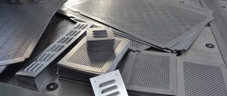
works with plasma and laser computer numerical control (CNC) machines, as well as stamping, scrolling and coordinate punching machines. The program has great functionality for cutting sheet metal, i.e. It is focused not only on the production of air ducts, but also flat parts, signs, weather vanes, roof elements, etc.
Compatible with any equipment
System PractiCAM™supports many models of plasma and laser CNC machines, interacts perfectly with machine control programs Mach3, Mach4 and Pumotix. It can also work with punching machines, spiral punching machines, jig punching machines, tube cutters and bar code readers. If your machine model is not yet in our library, then we will quickly write a post-processor for you completely free of charge, which will connect our program with your equipment.
Sheet metal unfolding program
The formula for the development length of a pipe blank helps to calculate the surface area or cross-section of a pipeline. The calculation is based on the size of the future route and the diameter of the planned structure. In what cases such calculations are required and how they are done, this article will tell you.
Cross-sectional area
The pipe is a cylinder, so calculations are not difficult
The cross-section of a round profile is a circle, the diameter of which is determined as the difference in the outer diameter of the product minus the wall thickness.
In geometry, the area of a circle is calculated as follows:
S = π R2 or S= π (D/2-N)2, where S is the internal cross-sectional area; π – number “pi”; R – section radius; D—outer diameter; N is the thickness of the pipe walls.
Note! If in pressure systems the liquid fills the entire volume of the pipeline, then in a gravity sewer only part of the walls is constantly wetted. In such collectors, the concept of open cross-sectional area of the pipe is used.
External surface
The surface of the cylinder, which is the round profile, is a rectangle. One side of the figure is the length of the pipeline section, and the second is the circumference of the cylinder.
Pipe development is calculated using the formula:
S = π DL, where S is the pipe area, L is the length of the product.
Inner surface
This indicator is used in the process of hydrodynamic calculations, when the surface area of the pipe that is constantly in contact with water is determined.
When determining this parameter, you should consider:
- The larger the diameter of the water pipes, the less the flow rate depends on the roughness of the walls of the structure.
On a note! If pipelines with a large diameter are characterized by a short length, then the value of the wall resistance can be neglected.
- In hydrodynamic calculations, the roughness of the wall surface is given no less importance than its area. If water flows through a water pipe that is rusty inside, then its speed is less than the speed of the liquid that flows through a relatively smooth polypropylene structure.
- Networks that are mounted from non-galvanized steel are characterized by a variable internal surface area. During operation, they become covered with rust and overgrown with mineral deposits, which narrows the lumen of the pipeline.
Important! Pay attention to this fact if you want to make cold water supply from steel material. The throughput of such a water supply system will be halved after ten years of operation.
The calculation of the pipe development in this case is made taking into account the fact that the internal diameter of the cylinder is determined as the difference between the external diameter of the profile and the double thickness of its walls.
As a result, the surface area of the cylinder is determined by the formula:
S= π (D-2N)L, where the indicator N is added to the already known parameters, which determines the wall thickness.
The workpiece development formula helps to calculate the amount of thermal insulation required
To know how to calculate the development of a pipe, it is enough to remember the geometry course that is taught in middle school. It’s nice that the school curriculum is used in adult life and helps solve serious problems related to construction. Let them be useful for you too!
§ 26. General information
Bending is a method of processing metal by pressure, in which a workpiece or part thereof is given a curved shape. Bench bending is performed with hammers (preferably with soft strikers) in a vice, on a plate or using special devices. Thin sheet metal is bent with mallets, wire products with a diameter of up to 3 mm are bent with pliers or round nose pliers. Only plastic material is subject to bending.
Bending parts is one of the most common metalworking operations. The production of flexible parts is possible both manually using support tools and mandrels, and on bending machines (presses).
The essence of bending is that one part of the workpiece is bent relative to the other at a given angle.
This happens in the following way: a bending force acts on a workpiece, freely lying on two supports, which causes bending stresses in the workpiece, and if these stresses do not exceed the elastic limit of the material, the deformation obtained by the workpiece is elastic, and upon removal of the load, the workpiece takes on its original view (straightens).
However, when bending, it is necessary to ensure that the workpiece, after removing the load, retains its given shape, therefore the bending stresses must exceed the elastic limit and the deformation of the workpiece in this case will be plastic, while the inner layers of the workpiece are subjected to compression and shortened, the outer layers are subject to tension and their length increases .
At the same time, the middle layer of the workpiece - the neutral line - experiences neither compression nor tension, and its length before and after bending remains constant (Fig. 93a). Therefore, determining the dimensions of profile blanks comes down to calculating the length of straight sections (flanges), the length of shortening of the blank within the radius or the length of the neutral line within the radius.
Instant and accurate cost estimates
During your work, the system PractiCAM™continuously creates an accurate cost estimate of all parts manufacturing costs. The full calculation takes into account the cost of material, labor costs for manufacturing parts, the cost of all fastening elements (bolts, screws, tires, rivets, etc.), as well as the cost of various accessories (blades, rods, flaps, etc.). The American SMACNA standard tables are given as an example, but you can create your own standard tables for calculating labor costs at your enterprise, taking into account the specifics of your production.
Ream length when bending sheet metal
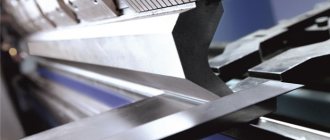
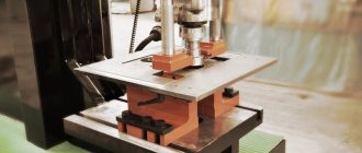
The material is bent by hand or on a bending machine, or with stamps under presses. Mostly small-sized parts are bent by hand.
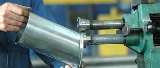
On a bending machine, sheet blanks and parts are bent in a straight line from various materials and at various angles, both to obtain various profiles of box-shaped shapes and for flanging small widths (5-30 mm).
When bending the material, in order to avoid cracks, you need to monitor the bend radius, guided by the data in table. 4.
Table 4 - Bend radii in mm
| Material thickness | Electron | Duralumin | Aluminum, copper, brass | Steel |
| 0,3 | 1.5 | 1.5 | 0,6 | O.6 |
| 0,4 | 1,5 | 1,5 | 0.6 | 0,6 |
| 0,5 | 2.5 | 1.5 | 0,6 | 0.6 |
| 0,6 | 2,5 | 2.5 | 1.0 | 1,0 |
| 0,75 | — | — | 1,0 | |
| 0,8 | 4,0 | 2.5 | 1,0 | — |
| 1,0 | 4.0 | 2.5 | 1,5 | 1,5 |
| 1,2 | 4,0 | 4,0 | 1.5 | — |
| 1,25 | — | — | — | 2.5 |
| 1,5 | 6,0 | 4,0 | 2,5 | 2.5 |
| 1,75 | — | — | 2,5 | |
| 2,0 | 10,0 | 6,0 | 2,5 | 2,5 |
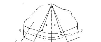
Before bending to a small radius, all parts are annealed. When bending, the material compresses and stretches (Fig. 194).
rice. 194.
Before the bend, the length of the line ab at the upper edge of the sheet blank at the bend is equal to the length of the line сd, located in the middle of the sheet blank, and the line mi at the bottom edge of the sheet blank.
After bending, the length of the arc ab is less than the length of the arcs c and pl.
This inequality shows that when bending, the material on the outside is stretched, and inside the curve it is compressed, and only the middle line CD does not change its length.
When bending sheet blanks from various materials to obtain a part of the required dimensions, the choice of permissible radii and determination of the lengths of the reamers (blanks) are of great importance.
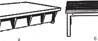
Bending with rounding (Fig. 195) requires a shorter workpiece than bending without rounding (Fig. 196).
Importing orders from 1C:Accounting program
In the 1C: Accounting program, you can create orders for cutting fittings, indicating their names, quantity, material, technological parameters, names of allowances, etc., and send them to the system PractiCAM™. Having received the order, the system
PractiCAM™
automatically finds the specified fittings in its libraries, applies the specified parameters to them and lays out their patterns on sheets of metal. After automatic installation, control commands for your equipment are generated, as well as various reports and labels.
AutoPOL7 scanning capabilities
Let's ask ourselves what types of models AutoPOL7 can deploy. The development functions in the program allow you to create developments of all types of 3D geometric models of uniform curvature. Objects that can be selected for unfolding are a variety of parts made using AutoCAD and Autodesk Mechanical Desktop: any three-dimensional spatial models, body parts, shells, NURBS surfaces, etc. In addition, you can unfold any objects described by mathematical dependencies: objects described by planes, cylindrical objects, conical, elliptical or spline surfaces. Using AutoPOL7 tools, developments can be constructed for geometric elements of double curvature.
Creating Labels
Mark parts in the system PractiCAM™easy and convenient. Various label templates are provided for your attention, but if they do not suit you for some reason, then you can create your own template. Add any information to your labels: your organization’s logo, barcodes, 3D images of parts, any part parameters you are interested in; edit these inscriptions in any style and font size. You can make a label for any fitting and flat part.
Useful Specifications
Specifications (SNiPs) of the system PractiCAM™allow you to set all the features of your production standards when working with various products, make it possible to unify production, automate the entry of products for production and reduce the number of errors when entering data, thereby increasing your productivity, and with it your profit. You can create your own rules for the production of products that are used in your enterprise.
AutoPOL7 as part of a unified system for technological preparation of production
Thousands of users around the world enjoy working with AutoPOL7. AutoPOL7's user interface capabilities enable you to create a professional-oriented environment that helps increase design efficiency and increase productivity when working on sheet metal fabrication. AutoPOL7 has all the benefits that come with ARX technology from Autodesk, Inc. and the Mechanical Desktop API. In addition, AutoPOL7 provides the ability to transfer information and product simulation results to MSC Software's Dytran software package. Engineers have the opportunity to control the manufacturing process and manage the quality of the product already at the computer design stage. This allows you to significantly shorten the cycle from design to obtaining a real metal product and save significant money due to the absence of defects in the product, as well as due to the absence of the need for modification or re-manufacturing of equipment. But we will talk about this in the next article.
"CAD and Graphics" 6'2000
- development sheet metal parametric model deployment perforation interface editing documentation detail curvature surface cad sheet rai angle bending nurbs drawing compensation bending radius thickness sheet Kx-factor control program dxf CNC arx
Possibility of manual and automatic segmentation for large products
System PractiCAM™allows you to segment (break into separate components) large-sized products that do not fit on a sheet of metal. You can set segmentation rules for each product yourself or entrust this process to the program.
Benefits of our technical support:
- The best product support - at the request of users, we develop and add new software modules, create new fittings and parametric flat parts, and add new methods for cutting fittings to existing ones.
- Free training on how to use the program.
- Regular updates of PractiCAM™
- a new release is released at least once every 2 weeks. - Development and addition of new labels and reports, placing on them the information necessary for the user.
Currently, a new version of the PractiCAM™
.
Its main difference is that the program is now divided into many functional modules that can be turned on and off in various combinations, reducing or increasing the set of functions performed by the program. Depending on the number of included modules, the price of the program is determined. PractiCAM™
can still be purchased in its entirety with all its capabilities, but you can also purchase either one of the standard software packages (each of which is a stripped-down version of the
PractiCAM™
) or the standard package with additional options.
Standard PractiCAM™ packages:
PractiCAM™ for typical parts.
This package allows the user:
- Use libraries of parametric flat (two-dimensional) parts, create flat parts using a graphic editor.
- Work with a graphic model of the part, specify dimensions, material and thickness.
- Use multiple layers when creating a part.
- Create a library of materials used, indicating the material thickness and type (sheet, roll).
- Import files with the extension .dxf, .dwg (AutoCAD, Compass, etc.).
- Use automatic placement of parts on sheets of metal using various algorithms, including combined cutting.
- Lay parts on sheets of metal manually.
- Based on the installation results, generate and print installation maps.
- Based on the laying results, automatically generate a sequence of control (CNC) commands for the cutter.
- Set cutter parameters (table dimensions, positioning and orientation of the table, size and shape of the cut at the entrance and the cut at the exit, cutting and idle speeds, cut compensation, automatic placement of jumpers on parts).
- Determine the method of transmitting control commands to the cutter (via a file or COM port).
- Import/export files with the .pmx extension (PractiCAM™ program files).
PractiCAM™ for ventilation.
This package allows the user:
- Use libraries of shaped products (fittings).
- Work with a three-dimensional graphic model of a fitting, set dimensions, allowances, material, determine the method of cutting the fitting.
- Work with the library of fittings accessories, specify dampers, stiffeners, couplers, rotary blades.
- Use various marking notches, automatically generate bend lines, create marking lines.
- Create a library of materials used, indicating the material thickness and type (sheet, roll).
- Create a library of used allowances (connectors, locks, joints).
- Apply automatic laying of product patterns on sheets of metal using various algorithms, including combined cutting.
- Lay product patterns on sheets of metal manually.
- Based on the installation results, generate and print installation maps.
- Based on the laying results, automatically generate a sequence of control (CNC) commands for the cutter.
- Set cutter parameters (table dimensions, positioning and orientation of the table, size and shape of the cut at the entrance and the cut at the exit, cutting and idle speeds, cut compensation, automatic placement of jumpers on parts).
- Determine the method of transmitting control commands to the cutter (via a file or COM port).
- Automatically segment (cut into pieces) large patterns.
- Automatically add allowances when segmenting patterns.
- Create and edit seam allowances connecting segmented parts of patterns.
- Create tables for recalculating fitting section parameters and apply them when creating fittings.
- Import/export files with the .pmx extension (PractiCAM™ program files).
PractiCAM™ Classic.
This package combines the “PractiCAM™ for standard parts”
and
“PractiCAM™ for ventilation”
, providing all the possibilities that they have.
The list of additional options (program features) for packages is given in the table.
If you want to learn more about PractiCAM™, then at a time convenient for you, completely free of charge, we can conduct a demonstration of the program using Skype or Team Viewer, at the same time answering all your questions. Also, completely free of charge, we can write a postprocessor specifically for your machine controller and activate PractiCAM™ for 1 month so that you can evaluate all the capabilities of our program directly in your work. All you need to do is call us or write us an email, or leave your contact information by filling out the following form:
Video presentation of PractiCAM
Video presentation of PractiCAM for typical parts
Calculation of developments and interface of the AutoPOL7 package
AutoPOL7 has a modern, intuitive interface. The software package allows you to create flat drawings of part developments very quickly and with high accuracy. When creating drawings of part developments to take into account bending, the development subroutine uses the corresponding Kx-factor. To calculate sweep lengths, the program uses the compensation method. AutoPOL7 uses the Kx factor to calculate bending tolerances. You can use the Kx factor formula according to DIN 6935 or the corresponding values from the material file. These values are experimental. They depend on the bending angle and the ratio of the internal radius to the sheet thickness. AutoPOL7 has a material file with Kx-factor values, which allows, in most cases, to generate accurate developments of product models. However, the values of the Kx factor depend on many other parameters. Decreases in material strength, sheet thickness and the friction of the tool used to bend the sheet can result in a decrease in the Kx-factor value. Therefore, users have the opportunity to change the values of the Kx-factor and independently expand existing libraries and knowledge bases. AutoPOL7 easily adds bend lines and bend angles to flat pattern drawings. AutoPOL7 is a user-configurable system based on user knowledge. The program uses an intelligent learning solver, which, while working with the user, gradually “absorbs” his knowledge and experience.