Automation of industrial equipment increases the pace of development every year. In the next 10-20 years, about 70% of production in developed countries of the world is planned to be switched to a completely human-independent work format.
In today’s article we will tell you what automated control systems are + provide instructions for assembling a CNC metal milling cutter with your own hands. Both simple options for assembling the unit and advanced “home” versions of expensive factory devices will be considered.
What is a CNC machine?
The first software products used in machine tools were developed back in 1804 - these were punched cards with binary code. Further, fist-type mechanisms came to replace them, which ensured smooth operation of the mechanisms, but lost in the simplicity of developing algorithms. The first numerically controlled electric motor machine was developed by Personson, and its industrial use began in 1949 - the unit was used for stamping parts for aircraft.
In the vastness of the Soviet space, the first CNC device was the 1K62PU screw-cutting lathe. The development of the equipment dates back to the second half of the 60s. Since 1980, the build-up of automated machine tools has increased dramatically around the world, and in 2022 you can see an incredible surge in this field of activity.
1) The concept of a CNC machine and the advantages of the technological solution
The direction is not easy to understand, therefore, before directly developing a CNC metal milling machine with your own hands, it is necessary to study a certain theoretical basis.
CNC is an analogue of two foreign abbreviations:
- NC (Numerical control).
The progenitor of modern control systems. It is based on control of operation through rigid circuits (plugs, switches, and so on). Algorithms are stored on external media, and there is no RAM as such;
- CNC (Computer numerical control).
Current equipment control systems that use specialized software to operate. The most important elements of systems in the hardware aspect are controllers and processors.
At cereal factories, work takes place according to the model of an automated workstation, where work programs are transmitted to equipment via a local/global network. Modern CNC machines can increase the speed of work by 3-5 times compared to manual production of parts.
Important: modern CNC equipment operates in two interrelated areas - CAD and CAM. The first system is responsible for the design, and the second for its direct production.
CNC equipment is a mechanism that produces a new part by subtracting excess from the workpiece. Some also include 3D printers in this direction, but such devices can only indirectly be called machine tools, because they create parts from scratch.
Advantages of CNC equipment:
- Minimizing the influence of the human factor on the equipment operation process.
- The speed, smoothness and direction are set in advance, and there are very few failures in the operation of such programs.
- No marking operations are required.
- Simple operation and reconfiguration of algorithms for different types of parts.
- High speed.
- The minimum volumes of defects are the wrong size, breaks, and so on.
- Efficiency in performing diverse types of tasks.
- Regularity in time allows you to plan production and predict the timing of orders in advance.
Although CNC machines have a lot of positive qualities, you should not neglect the shortcomings of the equipment - high cost, imperfect software and narrow focus on processes. CNC machines are good for mass processing, but for unique elements, this approach will not work.
The table below will tell you about the components of modern CNC devices. Having studied the components in detail, creating a CNC machine with your own hands on metal in the future will be much easier than doing everything at random using primitive drawings from the Internet.
| Knot | Component Tasks |
| Workpiece processing software | Algorithm of actions for the machine hardware in encoded form. The program performs the functions of turning on or off other components of the system + forces them to process the part according to the previously specified instructions, consisting of Latin letters and numbers. |
| Input device | For PC hardware connoisseurs, this point is easy to understand. For advanced CNCs, data entry was carried out from the keyboard. In less prosperous factories, reading equipment based on magnetic tape or punched paper is used. |
| Control device | Central CNC unit. Here, signals from the input device are decoded, axis interpolations + their motion patterns are implemented, speed is adjusted, and other auxiliary tasks are launched that are available in the machine system. |
| Drive unit | The assembly includes amplifier circuits, ball screw type transmissions + the motor itself. Thanks to amplification of signals from the control system, the machine quickly puts into operation mechanisms for adjusting the position of moving equipment components. |
| gun | Most machines have a standard processing set - a table, a working head with a processing tool that can move along 1, 2 or 3 axes, depending on the model of the CNC machine. |
| Measuring system | All kinds of sensors that record data in real time. The information received is compared with the parameters specified in the program, and if the data does not match, the control system adjusts the values to the required ones - speed, angle, immersion depth, etc. |
Thanks to a pre-developed work algorithm, the human factor influencing work is minimized. The role of humans in modern CNC machines is the operator and maintenance personnel. When controlling, this means pressing a couple of buttons and turning the unit on/off from the outlet. Maintenance + repair is much more difficult - this is already done by specialized specialists.
2) Classification of CNC machines + areas of application of equipment
Such equipment is designed to process any type of raw material - from plastic to durable steel grades.
Depending on the selected material of the parts to be processed, the equipment should be divided into 5 categories. Distribution of machines by type of processing:
- drilling The mechanism is based on a drill, which, due to a rotational movement, makes holes of the required diameter, or “slides” the workpiece to obtain irregular shapes;
- turning Here the object itself is already rotating along/counterclockwise or at a certain angle. The drill head remains motionless;
- milling The cutting attachments of the heads help to get rid of unnecessary materials from the workpiece and give it the required shape;
- chemical/electrical. A special direction in processing, where specialized technologies for cutting metals are used. For example, EDM ultrasonic or photochemical processing;
- others. This includes all technologies that do not fit into the above - laser processing machines, oxygen cutting, and so on.
2 options for assembling a metal lathe with your own hands
More often than others in everyday use (although CNC machines themselves are a curiosity in everyday life), milling cutters and units for processing soft metals or wood are used. The table below will tell you more about the classification of CNC machine tools.
| Classification parameter | Components | Description |
| Movement | Spot | For operation of the equipment, fixation of both the part and the implement is required. Such machines are called units with position processing. The CNC controls the transitions from point to point. |
| Contour | Here the workpiece remains in a fixed position, and the processing element moves along a given path. Hardware control provides for 2 axes of movement simultaneously, and the position of the head and the workpiece must be constantly monitored. | |
| Control system | Open | The operating algorithm is supplied by the operator through a peripheral input device. The information is converted into impulses, which, with the help of servo amplifiers, drive the machine components into action. The disadvantage of such CNCs is the lack of feedback, which does not allow extremely precise control of the operation of the system in general. |
| Closed | There is a feedback system, which increases the accuracy of the machine. About 90% of CNC systems in production operate on this principle. | |
| Axles | 2-axis | An example is lathes. Movement occurs along each of the axes at an angle of 90 degrees. |
| 3-axis | Movement along the X/Y/Z axes. | |
| 4-axis | One of the axes is a rotating mechanism | |
| 5-axis | 4-axis + one more axis - this is a multi-position rotary table. | |
| Drive unit | Hydraulic | The advantages are ultra-precision and smoothness with power, but such machines are an order of magnitude more difficult to maintain than their analogues. |
| Electrical | Servomotors with AC or DC current. Their advantage is their compactness and ease of management. The best option for a do-it-yourself CNC metal milling machine. | |
| Pneumatic | The working substance is compressed air. Such drives are relatively inexpensive + simple in design and fire safety. Disadvantages: low power, noise and lower positioning accuracy. |
When starting a manufacturing business, machine tools with software are an expensive but correct solution. Increased purchasing/maintenance costs are offset by labor savings. Instead of 10 people, production will require 2-3 operators.
Select the desired value 220 / 380
Extract from “Grounding of electrical installations up to 1000V according to PUE 7”
1.7.101. The resistance of the grounding device, ... at any time of the year, should be no more than 8 Ohms, respectively, at a linear voltage of 220 V of a single-phase current source.
Extract from “Grounding of electrical installations up to 1000V according to PUE 7” 1.7.101. The resistance of the grounding device, ... at any time of the year, should be no more than 4 Ohms, respectively, at a linear voltage of 380 V of a single-phase current source.
↑ Let's go!
Well, friends?
Let's hit the road! Read the letters, look at the pictures, and as one artist sang “Look at me, do as I do”! Fragment excluded. The full version is available to patrons and full members of the community.
Let's consider only the X axis, and you can configure the rest yourself according to the same principle.
Steps per
parameter indicates how many steps it takes your motor to complete a full revolution. The standard SD has a step of 1.8 degrees, i.e. we divide 360 degrees (full revolution) by 1.8 and get 200. Thus, we found that the engine in STEP mode rotates 360 degrees in 200 steps. We write this number in the Steps per field. Accordingly, in the HALF-STEP mode there will be not 200, but 2 times more - 400 steps. What to write in the Steps per field, 200 or 400, depends on what mode your controller is in. Later, when we connect to the machine and calibrate, we will change this parameter, but for now set it to 200 or 400.
Velocity
– sets the maximum speed of movement of the portal. For reliability, I set it to 1000, but when working, I decrease or increase it right on the fly in the main Macha window. In general, it is recommended to enter a number here that is 20-40% less than the maximum possible that your engine can produce without skipping steps.
Acceleration item
– acceleration. The value entered in this line, as well as the speed, depends on your engine and power supply. Acceleration that is too low will significantly increase the time it takes to process a figure with complex shapes and terrain, while acceleration that is too high increases the risk of skipping steps when starting because the engine will start to stall. In general, this parameter is set experimentally. From my experience, 200-250 is the optimal value.
Step pulse and Dir pulse
. From 1 to 5, but maybe more. If your controller is not very well assembled, then stable operation is possible with a longer time interval.
I forgot to say that most likely every time you start Mac, the Reset button will blink. Click on it, otherwise it won't allow you to do anything.
Ugh. Well, now let's try to download the control program, an example of which you can download at the end of the article. Click the Load G-Code
or go to the
File/Load G-Code
, whichever is more convenient, and the window for opening the control program appears.
The UE is a regular text file in which coordinates are written in a column. As you can see in the list of supported file types, there is a txt format, therefore it can be opened and edited with a regular notepad, like files with the extension nc, ncc, tap. You can correct the G-code in the program itself by clicking the Edit G-Code
.
We load the UE and see that a code has appeared in the left window, and in the right window the outline of the figure that we will cut out.
To start processing, all that remains is to press the green
Cycle Start
, which is what we do. Numbers began to appear in the coordinate window, and a virtual spindle moved across the picture, which means the processing process has successfully begun and our virtual (for now) machine has begun to process the part.
If for some reason you need to pause the operation of the machine, click Stop. To continue, press Cycle Start again and processing will continue from the same place. I was interrupted several times during the rain when I needed to turn off and cover the machine.
The speed is changed using the “+” “-” buttons in the Feed Rate
, and is initially equal to 100% of the speed set in Motor Tuning. Here you can adjust the speed of movement of the portal to certain processing conditions. The speed is adjustable in a very large range from 10 to 300%.
That's basically all about setting up Mach3, I hope I haven't forgotten anything. A little later, when we calibrate and launch the machine, I will tell you about some more necessary settings. Now grab some tea, coffee, a cigarette (whatever you like) and give yourself a moment of rest so that with new strength and a fresh mind you can begin setting up the electronics of the machine.
Operating principle
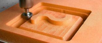
Milling machines are ideal for precision wood processing. The technology will be similar to the work of a sculptor who cuts off unnecessary parts of a part. In such a situation, the main functions will be performed by the cutter.
A tool with sharpened edges will rotate at high speeds, which will speed up operations PHOTO: promzn.ru
The device is driven by an electric motor. To ensure the required precision of movements, special mechanical devices are used.
Do-it-yourself copy-milling machine for wood
A large number of parts, furniture elements, and other products require shaped, highly precise and accurate execution. At the same time, it is necessary to ensure complete analogy in the entire circulation of blanks. It is almost impossible to achieve such an effect with your own hands. For this, a copy-milling machine is used.
The undoubted advantage of such a device is that, despite the simplicity of the device, it performs quite complex patterns PHOTO: youtube.com
In addition, the device will be indispensable for drilling holes for a number of elements (for locks and handles, forming frames for mirrors, and other work).
To ensure that all parts, blanks and products are identical, the wood cutting machine uses templates in its work. They are three-dimensional samples made of wood, plastic and other materials. To ensure high-precision work, vacuum pressing of workpieces and automatic template feeding are used.
Thanks to the perfect copying of the template boundaries, you will get identical finished products with complex patterns and holes of the required shape PHOTO: met-all.org
Main products
Today there are a huge number of items that can be made using a CNC machine, such as:
- Unique furniture made from various materials, including precious woods.
- Souvenirs: various boxes, photo frames, figurines, etc.
- Advertising products: beautiful massive letters, signs, etc.
Let's take a closer look at each of the proposed options.
Designer furniture. It surrounds us everywhere: bedrooms, kitchen, children's room. Modern furniture production is very thoughtful and has high precision.
Steps to create a product on a CNC machine:
- Sketch development. For this item, there are a large number of programs that help virtually simulate the situation. To create a 3-dimensional layout of a drawing, use computer programs such as CAD. The prepared computer files will make it possible to produce a furniture product on a CNC milling machine.
- Preparing the model for the machine. A ready-made sketch in 3D as a basis for the manufacture of any set of parts. To this sketch it is necessary to add a ray function (a vector that will be responsible for the direction of the cutter relative to the workpiece). There is also automatic model formation, which is quite convenient and will help save your time. Modern equipment simplifies the manufacturing process and transfers even the smallest and most difficult lines.
- Selection of the type of cutting tools, setting the power and processing mode.
- Loading files into the machine's memory, installing cutting tools, securing the workpiece and starting production. The CNC milling machine does further work independently according to an already specified program.
- Final assembly. It will take a small amount of time, there is no need to adjust parts.
Souvenir products. These may be the following souvenirs:
- wooden boxes that can be decorated with ornaments;
- boxes for beads or sewing supplies;
- jewelry boxes;
- icons and much more.
The most popular products among souvenirs are those products that are made using 3D or 2D vector drawings.
Also, multi-spindle machines (2-16 spindles) are now being introduced into production on a large scale.
Promotional Products. Its creation is a relevant type of activity today, in which the use of milling machines with numerical control is very popular. Such machines cope well with tasks such as the production of light boxes, stands, panels, curly inscriptions and outdoor advertising signs, as well as the preparation of structures for exhibitions.
A CNC machine helps to perform the following operations that are related to advertising products:
- cutting wood, acrylic and other materials;
- engraving/cutting of massive inscriptions;
- creation of a logo, emblem;
- production of signs, stands, etc.
To summarize, we can say that the number of products that can be made on a CNC milling machine is huge. All you need is equipment, a desire to work and a little experience.
↑ Method No. 2
This method can only be used if the base of the machine, the frame, is made exactly with right angles and is also absolutely flat in the horizontal plane.
We move the portal to its extreme position, to the CD side, move the spindle to point C and use a tape measure to measure the distance from the tip of the cutter to the frame. We move the spindle to point D and again measure the distance from the cutter to the frame. Ideally it should be the same. Now that the machine is aligned in all directions, you can install the lead screws and begin adjusting the gantry movement, which are made in the machine control program. In it we will set the parameters of your lead screw. The first thing to do is determine the thread pitch of your leadscrew. If you are using a construction pin or something else with a standard metric thread as a lead screw, here is a small table with M6-M22 threads. If you are the happy owner of a ball screw, you should know it yourself.
So. We know the thread pitch. Now you need to calculate how many revolutions the motor needs to make to advance one of the axes per unit length, which is 1 mm. To do this, unit (1) must be divided by the propeller pitch.
Example for M12 screw: 1/1.75=0.57142857. There is no need to round to tenths or hundredths; the more precise, the better. Now let's go to Motor Tuning and figure out what needs to be entered in the Steps Per field instead of what is already there. To do this, multiply the previously obtained value of 0.57142857 by the number of steps per full revolution of the engine (200 or 400, depending on the Step or Half-Step mode). That is, 0.57142857×400=228.571428 for half-step, and accordingly 114.285714 in step mode. I remind you that this value is only valid for M12 threads. For the other, perform the appropriate calculations. I could add an additional column with results to the table, but it seems to me that when you do something yourself and understand why it is needed, it will be much better than stupidly taking the finished result.
Kinds
There are the following types of electrical circuits:
- structural, which determines the relationship of parts of electrical equipment;
- functional, defining electrical processes in a separate unit, completely for a CNC machine;
- the fundamental one, which reflects all the elements and gives an idea of the principle of operation;
- installation plan connections for electrical connections;
- location of parts of electrical devices, conductor and cable products.
The technical documentation of the device usually contains a circuit diagram and electrical equipment layout diagrams. It is carried out without adherence to scale and without indicating how individual elements are actually located.
Selection of design features
The list of actions when developing and manufacturing a mini device for wood milling is as follows:
- First you need to decide what kind of work you are talking about. This will tell you what dimensions and thicknesses of parts can be processed on it.
- Make a layout and a proposed list of parts for a homemade desktop machine for making it yourself.
- Select software to bring it into working condition so that it works according to a given program.
- Purchase the necessary components, parts, products.
- Having the drawings, make the missing elements with your own hands, assemble and debug the finished product.
↑ Method No. 1
We bring the portal with the spindle all the way to point A. Where the cutter or needle touched the table, we make a mark, then to points B and C. We stretch the thread, securing it with tape on the marks made. Now we take a square and see if there is a right angle between ABC. If not, unscrew the portal with the mechanics of the Y, Z axes on one side from the corner of the X-axis guide, and move it in the desired direction, having previously bored out the holes for the bolts securing the portal to the corner.
Manufacturing Features
The arsenal of home craftsmen's tools is extremely diverse.
Particular attention is paid to the milling machine. This device is equipment that allows you to perform many operations on metal, wood, plastic and other materials.
The dimensions, power and set of functions of milling devices may vary, but each machine is based on a standard principle: a fixedly fixed workpiece is processed with a milling cutter - a special cutting tool with teeth (cutting blades).
Having all the necessary tools and materials available, craftsmen in their workshops can easily and in a short time assemble a compact device - a homemade router. Of all the existing types of milling machines, the most popular in home workshops is the vertical milling machine. This tool has a very simple design and uses inexpensive materials to assemble it. However, the type of machine is determined by the tasks that the master needs to perform. The following types of milling equipment exist:
- horizontally positioned tool;
- vertical device;
- copying device with pantograph.
In addition, you should consider the size and location of the machine - floor or tabletop.
Owners of any milling machine can perform high-quality processing of blanks and products made of metal and wood. In industry, milling machines are classified as multifunctional units. Self-made structures are endowed with a sufficient number of operations through which high-quality finishing is available, so they can also be considered multifunctional.
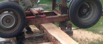
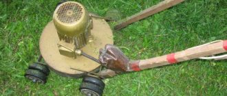
Design options: making a milling machine from improvised means
The equipment can be constructed from a drill, an angle grinder, or a washing machine. These are the most popular household options. The devices are produced with less power and are of a manual type, but are suitable for minor work.
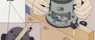
How to make a functional wood router from a regular drill
Here a stand is built and the equipment is changed. These are the main criteria for creating such a router option.
The cutter shank is fixed in the chuck. You can make a vertical and horizontal router (example 1 and 2). The stand is made from laminated chipboard.
Example 1:
Example 2:
Advantages and disadvantages of a drill router
The advantages of such a device:
- Easy to use.
- Little dust from work.
Minuses:
- Poor quality of the result due to low speed (3000 rpm).
- Very narrow range of functions.
How to make a router from a grinder
There are two ways:
- A collet is screwed onto the tool spindle. Work can be done with all accessories that have cylindrical shanks.
- A standard jaw-type chuck (from a drill) is attached to the spindle.
Milling cutter from a washing machine engine
A table is created using the described method. The motor shaft is placed on a collet. For this, a special adapter is ordered.
A lifting system is created to control the output of the tool: a motor and a threaded rod are mounted on two pipes.
One end of it goes into the nut fixed to the bottom of the table, and the other ends into the lower side of the engine. The rotating device – the wheel – is firmly fixed on it. The height is adjustable due to this.
↑ Software
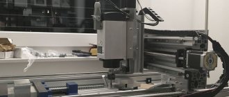
Since we won’t be able to fully test the assembled controller without a computer with a configured machine control program, we’ll start with it.
At this stage, no tools are needed, all you need is a computer with an LPT port, hands and a head. There are several programs for controlling a CNC machine with the ability to load control code, for example, Kcam, Desk CNC, Mach, Turbo CNC (under DOS), and even an operating system optimized for working with a CNC machine - Linux CNC.
My choice fell on Mach
and in the article I will consider only this program. I will explain my choice and describe several advantages of this program.
— Mach has been on the market for several years and has established itself as a very worthy solution for controlling a CNC machine. — Most people use Mach 2/3 to control their home machine. — Due to its popularity, there is quite a lot of information on the Internet about this program, possible problems and recommendations on how to fix them. — Detailed manual in Russian — Possibility of installation on a weak one. I have Mach 3 installed on a Celeron 733 with 256MB of RAM and everything works great. — And the main thing is full compatibility with Windows XP, unlike, for example, Turbo CNC, which is designed for DOS, although TurboCNC is even less demanding on hardware.
I think this is more than enough for you to choose Mach_e, but no one forbids you to try other software. Perhaps it will suit you better. Another thing worth mentioning is the presence of a driver compatible with Windows 7. I tried this thing, but it didn’t work out very well. Perhaps due to the fatigue of the system - it is already two years old and overgrown with all sorts of unnecessary garbage, and Mach is recommended to be installed on a fresh system and to use this computer only for working with the machine. In general, everything seems to be working, but the motors regularly skip steps, while on a computer with XP the same version of Macha behaves great.
Let's start production
To start making a CNC machine out of an old printer, you will need some parts that come with inkjet printers:
- Drives, pins, guides from the printer (it is advisable to use several old printers; the printers do not necessarily need to print);
- Drive from floppy drive.
- Material for creating the body - plywood, chipboard, etc.
- Drivers and controllers;
- Materials for fasteners.
The resulting numerically controlled machines will be able to perform various functions. Everything ultimately depends on the device that will be located at the output of the machine. Most often, inkjet printers are used to make a CNC milling machine, a burner (by installing a burner at the output of the device) and drilling machines for creating printed circuit boards.
The basis is a wooden box made of chipboard. Sometimes they use ready-made ones, but it’s not difficult to make it yourself. It is necessary to take into account that electronic components and controllers will be located inside the box. It is best to assemble the entire structure using self-tapping screws. Do not forget that the parts must be positioned relative to each other at an angle of 90 degrees and fastened as firmly as possible to each other.
↑ The soldering iron case is afraid
I'll start with the power supply. I planned to do an impulse one, I tinkered with it for probably a week, but I still couldn’t overcome the excitement that was coming from out of nowhere. I change the trans to 12V - everything is OK, but when I change it to 30 it’s a total mess. I came to the conclusion that some kind of bug climbs through the feedback from 30V to the TL494
and demolishes its tower.
So I abandoned this impulse generator, fortunately there were several TS-180s, one of which went to serve the homeland as a trance power supply. And whatever you say, a piece of iron and copper will be more reliable than a pile of powder. The transformer was rewound to the required voltages, but it needed +30V to power the motors, +15V to power the IR2104
, +5V to
the L297
, and the fan. You can supply 10 or 70 to the motors, the main thing is not to exceed the current, but if you do less, the maximum speed and power are reduced, but the transformer did not allow more because needed 6-7A. Voltages 5 and 15v stabilized, 30 left “floating” at the discretion of our electrical network.
All this time, every night I sat at the computer and read, read, read. Setting up the controller, choosing programs: which one to draw, which one to control the machine, how to make mechanics, etc. and so on. In general, the more I read, the scarier it became, and more and more often the question arose “why do I need this?!” But it was too late to retreat, the engine is on the table, the parts are somewhere on the way - we must continue.
It's time to solder the board.
The ones available on the Internet did not suit me for three reasons: 1 - The store where I ordered the parts did not have
IR2104
in DIP packages, and they sent me 8-SOICN.
They are soldered onto the board from the other side, upside down, and accordingly it was necessary to mirror the tracks, and there are 12 of them ( IR2104
).
2 - I also took resistors and capacitors in SMD packages to reduce the number of holes that needed to be drilled. 3 - The radiator I had was smaller and the outer transistors were outside its area. It was necessary to shift the field switches on one board to the right, and on the other to the left, so I made two types of boards.
↑ Preface
After I assembled my small machine without significant expenditure of effort, time and money, I became seriously interested in this topic. I watched on YouTube, if not all, then almost all the videos related to amateur machines. I was especially impressed by the photographs of products that people make on their “ home CNC
”.
I looked and made a decision - I will assemble my own large machine! So, on a wave of emotions, without thinking everything through, I plunged into the new and unknown world of CNC
.
I didn't know where to start. Vexta stepper motor
by 12 kg/cm, by the way with the proud inscription “made in Japan”.
While he was traveling across Russia, he sat in the evenings on various CNC forums and tried to decide on the choice of a STEP/DIR controller
and a stepper motor driver.
I considered three options: on the L298
, on field workers, or buy a ready-made Chinese
TB6560
about which there were very conflicting reviews.
For some it worked without problems for a long time, for others it burned out at the slightest user error.
Someone even wrote that it burned out when he slightly turned the shaft of the motor connected to the controller at that time. Probably the fact of the unreliability of the Chinese played in favor of choosing the L297+IRFZ44
, which is actively discussed on the forum. The scheme is probably really indestructible because... The driver's field amperes are several times higher than what needs to be supplied to the motors. Even though you have to solder it yourself (that’s just a plus), and the cost of the parts was a little more than a Chinese controller, but it’s reliable, which is more important.
I'll digress a little from the topic. When all this was done, the thought did not even arise that I would ever write about it. Therefore, there are no photographs of the assembly process of mechanics and electronics, only a few photos taken with a mobile phone camera. Everything else was clicked specifically for the article, in already assembled form.