Electrical Diagram of Drill
If the light comes on, everything is fine with the button, but if you notice a malfunction, it’s time to replace the button.
The simplest diagram, and best demonstrating the principle of operation, is the following. That's all, in conclusion I can say that the method I told you works very well, I have tested it myself more than once.
If the light comes on, then everything is fine with the button, but if not, then the easiest way to fix the problem is to replace it. What's inside Drill repair. This happens very often, do it yourself
If the light comes on, everything is fine with the button, but if you notice a malfunction, it’s time to replace the button. In this case, repairs must be carried out using specialized tools.
More scientifically it looks like this. Since gearbox failure is the most common mechanical failure, we will dwell on its design in more detail.
The most simplified of all the diagrams and the one that best shows the principle of operation is shown in Fig. We connect the device to the contacts on the plug, but the device does not respond, because the start button is not in the working position.
I hope this helps, the drill is good.
If metal parts break, it is better to purchase a new unit.
The drill does not turn on, do it yourself REPAIR.
Procedure for identifying electrical faults
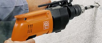
Determining the integrity of the electrical part of the Makita rotary hammer. In order to repair a Makita 2450 or Makita 2470 rotary hammer with your own hands, you need to arm yourself with devices and tools. Any tester, a set of screwdrivers, keys, a hammer, or a wooden adapter will do. It's good to have a screwdriver with a built-in phase indicator.
You need to take the tester, connect to the ends of the hammer drill plug and press the hammer drill switch. If the tester shows some resistance, then the power supply circuit of the hammer drill is intact.
If the tester shows infinity, then the integrity of the circuit is broken and it is necessary to remove the back cover to check the connecting cable and electric brushes of the hammer drill.
The back cover (usually black) of the hammer drill can be easily removed; you just need to unscrew three screws using a screwdriver or screwdriver.
Remove the cover and use a screwdriver to disconnect the ends of the wires from the electric brushes. Using a tester or a homemade device, popularly called an “arkashka,” determine the integrity of the supply wires and the correct operation of the switch.
A few words about a simple control device called “arkashka”. The device consists of an LED or flashlight bulb, a AA battery and two pieces of wire. The entire electrical circuit of the control device consists of parts connected in series. Connect the battery to one end of the LED or light bulb, and attach wires to the free ends of the LED and battery. You will get a universal device for checking the integrity of electrical circuits.
Typical malfunctions of the Makita 2450 and 2470 rotary hammers Common malfunctions in the electrical part of the Makita 2450 and Makita 2470 rotary hammers:
- fracture of the supply cable at the entry point into the hammer drill;
- failure of the switch button TG813TLB-1, art. 650508-0, pos. 68.;
- wear of electric carbon brushes SV-419, art. 191962-4, pos. 65;
- wear of reverse switch contacts;
- wear of rotor bearings: bearing 609LLU, art. 210060-6, pos. 51; bearing 607LLU, art. 211021-9, pos. 56;
- rotor short circuit 220-240 V, art. 515668-8, pos. 54;
- failure of the stator winding 220-240 V for HR2450, art. 633488-5, pos. 59.
The TG813TLB-1 switch, art. 650508-0, is used as a start button; pos. 68.
The brushes are replaced when they are completely worn out or have poor contact. This malfunction is detected by strong heating of the points where the electric brushes are installed.
Failure to turn on the hammer drill may be caused by abrasion of the contacts on the reverse switch. This type of problem can be fixed very simply.
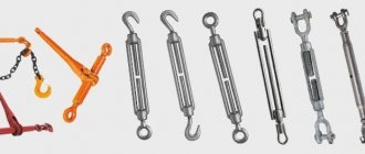
Repair of Makita rotary hammer reverse switch
To repair the reverse switch, you need to disconnect the back cover. Carefully disconnect the wires from the button. Carefully inspect the switch.
Further disassembly involves removing the brush holder, after first freeing the brushes themselves. By removing the brush holder, you will get to the reverse switch contacts. Determine its condition and replace the contacts if necessary.
Another common electrical fault is poor contact between the stator and the lower contacts of the reverse switch.
Repairing the contact between the stator and the reverse switch
To remove the stator, you need to disconnect the gear housing (black) from the stator housing (green).
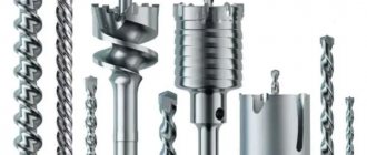
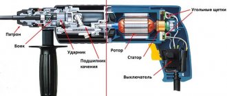
Perforator device
Rotary hammers come in different models and differ from each other depending on:
- functions performed;
- power;
- manufacturer.
Despite this, each hammer drill device has a mandatory structure in its design, composed of components and systems that serve to fulfill the main purpose of this unit. Each such device must have:
- gearbox;
- electric motor with armature and stator;
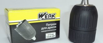
- cartridge;
- mechanism that produces the blow.
In the process of improving this device, additional functions have appeared that greatly facilitate its use.
The main ones:
- vibration suppression system;
- a mechanism that locks this tool in a position convenient for the operator - Vario-Lock;
- depth limiter for penetration into the working surface;
- cleaning the device from dust;
- operating mode switch.
The image shows in detail how the hammer drill works.
Disassembling the hammer drill and removing the cartridge
To repair a rotary hammer, you first need to disassemble it correctly. And we start doing this by disassembling the cartridge.
- Remove the rubber tip and retaining ring;
- Remove the washer and conical spring;
- We take out the side balls (preferably using a magnet);
- We put the operating mode lever in a position equivalent to the maximum and remove the switch handle. We fix the position;
- Remove the rear cover on the handle and the engine brush;
- Unscrew the 4 screws near the drill to remove the front cover;
- We take out the barrel and shaft, and using a screwdriver, remove the bracket and bearing;
- Open the back cover and remove the reverse switch;
- We remove the rotor by unscrewing the fasteners and disconnecting the terminals from the starter, which also needs to be removed by removing the protective casing.
Important! When disassembling, be extremely careful about where and when you remove certain parts. Fold them so that you never lose them. This determines whether you put the tool back or not.
Operational safety
A rotary hammer is an electromechanical tool, so it must be used while observing safety precautions.
- Before starting work, you need to make sure that the electrical cord is intact. A damaged plug or insulation on the cord may cause electric shock. Cracks in the housing can also be a source of danger.
- Replacement attachments must be securely fastened, otherwise they may jump out of the chuck during operation and cause injury.
- It is necessary to drill the material without touching the rotating part of the tool: sharp edges easily damage hands and other parts of the body.
- The attachments become very hot when rotating, so after finishing work you should not touch them with bare hands to avoid burns.
Operating power tools correctly means maintaining your health. Be sure to follow safety rules and wear personal protective equipment: gloves, a mask or goggles, and special work clothes.
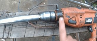
How to Disassemble Hammer Hammer 850 Psrh207
A hammer drill is a tool that requires stern work during its operation and disassembly. For this purpose, you should know its structure; all that remains for our client to do is to make the components included in the design of the tool. Rapid orientation in the device and knowledge of what and how to disassemble
a hammer drill will allow you to avoid unnecessary expenses both financially and in terms of labor.
A hammer drill, as opposed to an ordinary drill, is an option for easily drilling concrete and other strong materials.
Even the most insignificant malfunction of the device leads to breakdowns of a more severe nature. A step-by-step disassembly will allow you to quickly find if a tool is broken. It is important to know the cause of the breakdown and the methods that will allow you to remove it. Disassembling a tool requires following a certain sequence.
Operating principle and modes
The hammer drill operates in three main modes:
- Impact with rotation - makes it possible to drill through a hard and thick surface without much effort.
- Impact without rotation - allows you to hit concrete surfaces.
- Rotation without impact - turns the hammer into a drill.
Important! If you choose the right mode, the tool can be used in the process of gating for wiring. The result will be far from ideal, but all defects will be hidden by subsequent treatment of the walls.
The operating principle of the device is simple:
- Current passes through the electric motor, starting the remaining parts of the mechanism.
- The stator shaft begins to rotate due to its location on bearings. At its end there is a helical gear, which reduces the speed and increases the torque.
- Due to the rotation of the bearing, an impact option occurs.
This causes all the parts inside the hammer to move and interact with each other, transferring energy to the gear, which regulates the power and operation of the hammer.
The main differences in the designs of Bosch rotary hammers
When repairing a Bosch rotary hammer, you cannot do without an electrical diagram and a disassembly diagram for the tool of the model you are going to repair.
The electrical circuits of Bosch 2-20, 2-24, 2-26 rotary hammers are almost the same. Although there are some unprincipled differences.
But mechanical blocks are equipped with parts that differ structurally from each other. The main differences are concentrated in two units: the intermediate shaft and the barrel shaft of the shock block.
The greatest differences are presented in the design of the intermediate shaft, the “drunk bearing” assembly, and the mode switch. Unprincipled features are present in the design of the barrel of the striker block, firing pin, and striker.
Let's start with the Bosch 2-20 rotary hammer.
Safety clutch
In the event that a hammer drill chuck jams, safety clutches are activated, which are installed to reduce the likelihood of injury while performing the assigned task. An additional function of this mechanism is to protect the motor from overloads during operation. The operation of the device is based on disconnecting the cartridge from the drive shaft to prevent it from burning out.
The most commonly used are spring-cam or friction mechanisms. The difference is that in the first case, the operation of the tool is based on the principle of slipping of two couplings relative to each other. In the second, the disks are pressed against each other in their normal position. Sliding occurs only if the chuck stops functioning.
Additional functions of units
Regardless of the type and brand, most models of this German technology are equipped with a set of functions that increase the performance and ease of use of the devices. Almost all units are equipped with:
- Dust removal system. Let us especially note this element, since if it is present, you can forever forget what disassembly is. A Bosch hammer drill equipped with this function has an increased warranty period.
- Shaft rotation stabilizer.
- A rail that limits the drilling depth.
- "Soft start" system.
- Rotation speed regulator.
- Anti-vibration system.
- Safety device to prevent overheating.
Thanks to the various capabilities of the devices, any user - from a professional builder to a simple home craftsman - will be able to choose a Bosch hammer drill that suits his needs. Reviews about this tool are only positive and speak of its versatility, efficiency and consistently high quality.
How does the tool work?
You can find a huge number of rotary hammers with a variety of designs on the market. But regardless of the many modifications of the device, they all consist of approximately the same components.
Electric drive
The hammer drill is equipped with an electric drive as a motor. Typically commutator type drives are used. In light models that are purchased for work in domestic conditions, the engine is in a horizontal position. In medium and heavy ones it is fixed vertically.
Horizontal arrangement
Devices with horizontal drive are considered more compact and convenient when working in hard-to-reach places.
But this design also has its drawbacks.
For example, due to its location, the drive is poorly cooled, and its power component is subject to high loads.
But devices with a vertical drive are cooled much better. In addition, their design implies a reduced level of shock vibration. Also, thanks to the vertical placement, it allows you to give the piston a wide amplitude of movement, which also increases the amplitude of the striker. This advantage is explained by the fact that in a vertical arrangement a crank mechanism is used. But in devices with a horizontal motor, a rolling bearing is used. Thanks to this, rotary hammers with vertical motors are able to work much longer.
Impact mechanism design
The impact mechanism allows the hammer to perform its main function (drilling). The tool uses two main types:
- Electromechanical;
- Electropneumatic.
The first type of mechanism is used in most modern instrument models. Its main advantage is high impact energy with low power of the power structure. There are two types of electro-pneumatic mechanism. The first uses a rolling bearing (for light models), and the second uses a crank mechanism for heavy and medium models.
Impact mechanism diagram
Among the elements of the impact mechanism are the rolling bearing, ram, piston and firing pin.
During the start of operation, the impact force from the electric motor is applied to the inner race of the bearing.
At the same time, the outer ring begins to produce oscillatory movements. The internal volume of air between the ram and the piston is alternately under high and low pressure conditions. At this time, the ram repeats the movements behind the piston and hits the firing pin, which, in turn, hits the nozzle in the cartridge.
The pneumatic operating mechanism allows the device to turn off during idling. This became possible due to the displacement of the ram forward if there is no contact between the surface and the bit. During the movement of the ram, a hole opens to connect air from the piston chamber with the external environment.
The crank mechanism in rotary hammers operates with a high amplitude, which makes it possible to significantly increase the impact power (up to 20 kJ). The mechanism itself functions in almost the same way as the previous one. The torsional impulse is transmitted from the worm shaft to the gear, and then the crank sends it to the impact mechanism.
How to use a hammer drill in different modes
For convenience and proper performance of different types of work, rotary hammers have several operating modes. A toggle switch is provided to switch them.
Most modern rotary hammers operate in three modes:
- drilling;
- hammer drilling;
- chiselling.
Operating modes and their standard designation: drilling, hammer drilling, chiselling. You can adjust them using a switch
Drilling
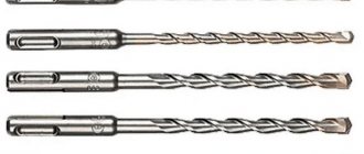
The mode switch is installed opposite the “drill” designation. To perform drilling work, use equipment with SDS shanks: a removable jaw chuck or hammer drills. This mode is necessary for forming holes in wood, metal and other materials.
Impact drilling
The switch is installed opposite the “drill + hammer” designation. This mode is designed for drilling holes in concrete, brick, reinforced concrete structures and other building elements. The cutting tool performs simultaneous rotational and translational movements. When drilling reinforced concrete structures, the likelihood of a collision with reinforcement should be taken into account; this is dangerous for both the tool and the person. In this mode, drills are used - drills with special carbide tips.
Hammer drilling mode enabled
Chiseling
The switch is installed opposite the “hammer” designation; in this mode, the working tool does not rotate. Used for punching grooves, destroying building structures, and during excavation work
It is important to hold the hammer drill firmly and confidently. For chiselling, special tools are used - chisels, peaks, blades
To make a hole, you need special tools - chisels, picks, spatulas, hammers
Reverse
The reverse rotation mode reverses the direction of movement of the drill or drill. In budget models of rotary hammers, electric reverse is used - the armature of the electric motor rotates in the opposite direction. Disadvantage: more intensive wear of the brushes and braking of the armature. Professional devices use a more complex mechanism - a gearbox, in which the direction is switched mechanically, using gears. This method is more reliable, however, models of rotary hammers with mechanical reverse switching have a higher cost.
Other modes
Some rotary hammer models have additional operating modes. For example, turning the chisel is designed for efficient chiselling. In this mode, the bit rotates a certain degree after each blow.
How to switch and adjust hammer drill modes
Switching hammer drill modes must be performed only after the working mechanism of the hammer drill has completely stopped. In this case, there is no need to disconnect the instrument from the network. You must make sure that the mode switch is clearly locked in the desired position.
How to connect a power tool without a diagram
Sometimes, when repairing or restoring the functionality of a power tool, it becomes necessary to connect the device to the network while maintaining all the functionality that the power tool originally had, but only wires stick out from the body, quite a lot of them (in my case 6), and the electrical circuit can’t be found anywhere . What to do? In fact, everything is not so scary and difficult.
A distinctive feature of a commutator electric motor is the commutator unit.
It is not at all necessary to know what and how was done initially. In order to connect the electric motor of the tool, you need to do the following:
- Find the supply circuit.
- If necessary, connect capacitors.
- Connect the switching device.
Method for finding power wires
In hand-held power tools for any purpose, as a rule, a universal commutator motor (UCM) is used. This versatility is very conditional and only means that the engine can theoretically operate on direct or alternating current. In practice, during repairs, this feature cannot be used; it is more important to know the circuit diagram of the UCD. By looking at which you can draw an important practical conclusion.
One of the bundle of wires entering the motor housing must certainly be connected to one of the stator windings, and through it to the contact pad of the brush.
To make sure of this, you need to unscrew or remove both plugs of the brush holders and remove the brushes. Then, touching one multimeter probe to the contact pad of one of the brushes, use the other probe to ring all the conductors in sequence. If the desired wire is not found, move to another site. In the end, the right guide will definitely be found.
In this case, it is convenient to use a multimeter with an audio signal. Depending on the design features of the device under study, the resistance in some circuits may be very small and this can be misleading.
Diagram and design of the Bosch 2-20 rotary hammer
Repairing a Bosch 2–20 rotary hammer is not possible without knowledge of the design of the tool being repaired.
The operating principle of the Bosch 2–20 rotary hammer is based on the transmission of torque from the rotor shaft, pos. 3, to the shaft of the impact block, pos. 22, through the intermediate shaft, pos. 824, while simultaneously transmitting a longitudinal impulse to the working tool.
Rotor pos. 3 transmits torque to the helical gear of the intermediate shaft pos. 824.
Diagram of a Bosch 2-20 rotary hammer
The helical gear is mounted on the intermediate shaft and transmits rotational torque to the shaft. A fixed bearing is attached to the shaft, receiving rotational torque through the clutch. Due to its design, the drunk bearing transmits translational motion to the barrel cylinder of the impact mechanism.
Design of the intermediate shaft of the Bosch 2–20 rotary hammer
The intermediate shaft of a Bosch 2–20 rotary hammer consists of a rolling bearing assembly (drunk bearing), a clutch, a large helical gear, and a small spur gear.
Most often, breakdowns manifest themselves in wear of the clutch splines, which leads to the loss of rotation of the hammer drill chuck in the presence of a shock pulse.
It can be corrected by replacing the clutch or restoring the teeth of the clutch parts.
View of the intermediate shaft of the Bosch 2-20 rotary hammer
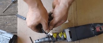
How to replace brushes: work in a couple of minutes
But the drill may not work due to trivial faults - for example, due to brushes inside the motor. This means that you can’t do without repairing brushes, and this work is quite simple - you don’t even need to have special knowledge and tools. To do this, we disassemble the device, remove the brush holders from it and replace parts that are broken. By the way, there are models whose body does not need to be disassembled - you just need to remove special plugs through the installation window, after which we change the brushes .
You can purchase these parts at any hardware store; there are also some models that are sold along with a set of additional brushes. It is important that you do not wait until the brushes are completely worn out - check them from time to time. And all due to the fact that there is a risk of a gap forming between the bristles and the collector. As a result, this part will begin to overheat and eventually fall off - which means you will have to change the entire anchor, which will be much more expensive and more difficult, and it is not a fact that you will be able to solve this issue yourself.
As you can see, there are a variety of breakdowns, many of which will be within your control, others will only be possible for specialists in service centers. And to reduce the risk of such breakdowns, you need to take care of your tool, clean it after work, check the condition of the parts and brushes in order to replace them with new ones in time. However, if you see that you can’t handle it yourself, take the device to a workshop.
Troubleshooting Methods
Self-repair of a rotary hammer is extremely difficult due to its complex design. Even disassembling the case is often an impossible task for a home craftsman.
In addition to appropriate education, specialists from service centers of leading brands have regular work experience, the necessary tools, and equipment.
In addition, a diagnosis of a power tool is made during the initial inspection, which allows you to plan your budget: invest in an existing tool without guarantees of long-term operation, or spend money on a new power tool with a long service life and a manufacturer’s warranty.
Disassembling the rotary hammer gearbox: 1 – special ring, 2 – releasing sleeve, 3 – ring, 4 – ball, 5 – spring 8 – casing, 22 – closing spring, 28a – switch, 29 – ring, 30 – spring, 31 – latch.
The hammer drill is used in different modes, which significantly reduces the life of the working parts. In addition, specialized companies more often use either slotting (concrete, stone work, restoration of buildings, foundations) or drilling (installation of household and industrial equipment). If in the second case, following the manufacturer’s recommendations on drilling modes, you can extend the service life of the power tool, then in the first option it is very difficult to calculate the load. For example, with a specified maximum concrete drilling of 24 mm, it is recommended to use drills in the range of 18-16 mm. Peaks for breaking concrete, stone, and brick are standard, so the tool experiences different loads.
If the power tool stops hitting, you can limit yourself to disassembling the spindle assembly in the following sequence:
- dismantling the mode switch lever - the parts are usually made of polymers and therefore are quite fragile;
- detachment of the boot - the rubber corrugation must be periodically replaced, since it often comes into contact with destructible materials, wears out, and cracks;
- with a dismountable cartridge, the brushes are first removed; screws are loosened and unscrewed;
- the body is divided into two halves.
Visual inspection in 90% of cases allows you to identify a malfunction and replace the damaged/worn part. Before assembly, lubricant must be added and replaced.
The difference between a drill and a hammer drill
Even when using the most powerful method of destruction of materials - explosion, initially holes for laying explosives are drilled using hammer drills. The question is often asked: what is the difference between a drill and a hammer drill? To answer this, it is necessary to consider the operating principles of these devices.
The drill creates low-amplitude vibrations, which facilitate the drilling process, but do not make it possible to work with “heavy” materials such as reinforced concrete. The mechanism is made in the form of two ratchets, stationary and located on the axis of rotation of the cartridge.
Impact mechanism from inside
When the impact function is disabled, the ratchets do not touch each other. When it is turned on, the stopper is removed, the drill resting against the wall closes the ratchet gears, and vibrations occur, facilitating the drilling process.
This design is easy to manufacture, but unreliable and not designed for high loads. Ratchet teeth wear out quickly and require constant lubrication.
Unlike an impact drill, a rotary hammer has a more complex design. It can withstand heavy loads and is designed for a longer service life.
Diagram of the impact mechanism
Anti-vibration system used in the tool
Diagram of the main parts of a rotary hammer that often break.
Companies are constantly developing new and improving existing systems aimed at reducing vibrations occurring in the tool. The entire variety of vibration protection systems can be divided into two types:
- active;
- passive.
The active anti-vibration system is mounted only on tools with high power. To reduce the level of vibration, a simple device is used, which consists of a counterweight with a spring device that absorbs all vibration loads. This system cannot completely compensate for all vibrations occurring in the tool; it only helps to significantly reduce its level. In addition, vibration damping is facilitated by the tool handle, which is attached to the body by means of a hinge joint and a spring mechanism.
The role of a passive system for reducing the level of vibrations that occur during operation is performed by rubber pads mounted on the body; in addition, such pads prevent hands from slipping. The passive system is ineffective.