Manufacturer information
Near the workshop in Zamoskvorechye, the Bromley brothers began construction of a mechanical plant in 1857. His first products were axes, sickles and other tools for peasants. In 1864, the brothers purchased a new plot and began to obtain permission to build new workshop buildings.
In 1870 and 1872, planing and drilling machines from Zamoskvorechye received gold medals at the Moscow Industrial Exhibition. The triple expansion steam engine was awarded the Grand Gold Medal at the International Exhibition in Paris.
In 1918, the plant was nationalized and modernized. Since 1922, the plant has completely switched to the production of metal-cutting machines. In 1971, the first machines of the 16K20 series were produced. After the reconstruction of the plant, in 1973 they began to produce 16A20F3 with CNC.
Important!
Since 2016, the Moscow Machine Tool Plant has been located in New Cheryomushki. The production of CNC lathes has resumed.
Operator's manual for screw-cutting lathe 16А20Ф3 with CNC 2Р22
This manual contains information for the operator on servicing the 16A20F3 S32 machine with a 2P22 or 2P22.01 CNC system. Contents of the operator's manual:
- Purpose of the program
- Program execution conditions
- Program Execution
- Operating procedure
- General provisions
- Linking the device to machine parameters
- Linking the reference system to the machine
- Linking a tool to a reference system
- Linking a reference system to a part
- Semi-automatic input of the initial position and exit of the tool to this position
- Input mode
- Program output
- Manual control mode
- Automatic mode
- Test mode
- Coding system and frame order
- Programming chamfers, arcs and fillets
- Programming canned cycles
- Drawing up programs when entering from punched tape
- Messages to the operator
- Device exchange signals
- Algorithms for the operation of electrical automation of a controlled machine
You can download the “Operator’s Manual for the 16A20F3 CNC 2P22 CNC lathe” (85 sheets) for free in good quality using the link below.
You can download for free “Instructions for programming a screw-cutting lathe 16A20F3 with CNC 2P22” (3 sheets) in good quality from the link below.
Purpose and scope
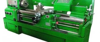
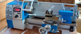
The 16A20F3 CNC chuck-centering lathe is designed for external and internal processing of medium-sized workpieces with a diameter of up to 400 mm and a length of 1000 mm. The equipment produces a stepped and curved profile with an offset relative to the axis of rotation. The entire processing cycle takes place automatically.
Model 16A20F3 performs external and internal processing:
- turning of cylindrical surfaces in one axis and with offset;
- elements having conical, spherical and other complex profiles;
- drilling along the end and radius;
- boring;
- thread cutting.
The chuck-centering CNC machine 16A20F3 is designed for finishing processing of complex-profile parts. It produces crankshafts, connecting rods, earrings and other products, individually and in large quantities.
Find out why the 1516 universal rotary lathe is so good.
Electrical circuit diagram of a screw-cutting lathe 16A20F3 with CNC 2P22
Below are sketches of two pages of the electrical circuit diagram of a 16A20F3 screw-cutting lathe with a 2P22 CNC device, a KEMROS main drive and a KEMTOR electric feed drive.
You can download a free electrical circuit diagram of a screw-cutting lathe 16A20F3 (21 sheets) in good quality from the link below. This machine uses an electric drive for the main movement KEMROS and an electric drive for feeds KEMTOR , so here are links to the documentation on these electric drives.
Location of components
Ball screw pairs of the X and Z axes have an increased service life due to reliable protection of the units. The spindle is high-precision, with a hole of 55 mm and 64 mm.
The frame has a chip removal conveyor. The support group consists of an apron and the base of a removable automatic turret. They are driven by a drive and a transverse movement VGK. The longitudinal movement of the tool is carried out through angular gears and a coupling from the VGK screws.
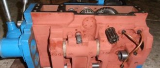
On the left above the frame in the housing there is a gearbox and spindle head. The chuck is installed mechanized and has its own electric drive. The tailstock is located on the bed guides. The quill is driven by an electromechanical drive. Push-button machine control panel. It is located on a bracket and easily changes its position.
Location of controls
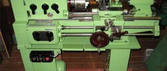
The machine control panel is located at the top of the headstock. Below is a handle for setting the spindle speed. The handle for manual movement of the transverse caliper is located on its body, above the apron.
The longitudinal movement of the carriage in manual mode is activated by the handle at the point where the shafts are attached, on the left. It turns on in the direction of movement of the unit. Below on the control pedal frame:
- clamping and releasing the cartridge;
- supply and removal of quills.
The quill is clamped manually using a handle on its body.
Important!
Control of all nodes is duplicated on a remote unit.
On the rear guard of the unit, at the top, a symbolic information display unit is mounted. BOSI is an element of visualization of the machining process and adjusts machining taking into account tool wear. Control of the drives is displayed on the panel in the upper right corner of the fence. The equipment control panel is placed forward on a bracket.
Machine design, passport
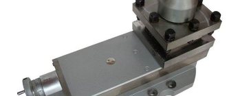
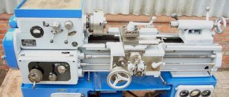
The design of the 16A20F3 model has its own characteristics. The machine kit includes replaceable tool heads with a rotating axis and a number of tool holders of 6, 8, 12. On a high bed cast from SCh20 cast iron there are heat-treated guides of increased wear resistance. The caliper and tailstock move along them.
The spindle receives torque from the main drive through the gearbox and gearing. A chuck is installed on it to secure the workpiece. When working with rolled products, after cutting the finished part, the workpiece moves to the working area automatically.
The tool disc has slots for several cutters, depending on the model. In the longitudinal direction it moves together with the caliper. The lateral movement is provided by a drive located under the turret body. The feed box is located in the apron. It has its own electric drive. No more than 2 movements are activated at the same time.
Important!
For safety reasons, all rotating and moving components have guards with limit switches. The machine will not start working until all the shields are in place.
The lathe's passport can be downloaded for free from the link - Passport of the chuck-center lathe with numerical control 16A20F3.
Passport for screw-cutting lathe 16A20F3
This operating manual “ Passport of the machine 16A20F3 ” contains information necessary both for the maintenance personnel of this machine and for the employee directly involved in working on this machine. This manual is an electronic version in PDF format of the original paper version. This documentation contains the Passport and Manual (instructions) for the operation of the universal screw-cutting lathe 16A20F3.
Content :
- GENERAL INFORMATION ABOUT THE EQUIPMENT
- MAIN TECHNICAL DATA AND CHARACTERISTICS
- COMPLETENESS
- SAFETY INSTRUCTIONS
- PART OF THE EQUIPMENT
- INSTALLATION PROCEDURE
- DESIGN AND OPERATION OF EQUIPMENT AND ITS COMPONENTS
- HYDRO- AND PNEUMATIC LUBRICATION SYSTEM
- OPERATING PROCEDURE
- INSTRUCTIONS FOR MAINTENANCE, OPERATION AND REPAIR
- POSSIBLE MALFUNCTIONS AND METHODS OF THEIR ELIMINATION
- FEATURES OF DISASSEMBLY AND ASSEMBLY DURING REPAIR
- SPARE PARTS INFORMATION
- MANUFACTURER'S WARRANTY
You can download the passport of the screw-cutting lathe 16A20F3 (54 sheets) in excellent quality from the link below. Since this machine is built on a 2P22 CNC device, in addition to this passport, various documentation on the 2P22 CNC is required.
Specifications
The processing accuracy on the 16A20F3 machine is 0.01 mm. The program has a resolution of 0.0–1 mm on both axes.
Technical characteristics of the lathe model 16A20F3:
- workpiece diameter above the bed 400 mm;
- above the caliper 220 mm;
- maximum workpiece length 1000 mm;
- spindle hole diameter 53 mm;
- the longest length of the workpiece when processing with a turret is 870 mm;
- main drive motor power 11 kW;
- number of spindle speeds 22;
- cutter height 25 mm;
- number of coordinates 2;
- CNC system – 2Р22;
- total power of the machine is 22 kW.
The dimensions of the machine are 3700×1700×2145 mm and the weight with CNC equipment is 4050 kg. The 16A20F3 CNC lathe is a leader in its use at large enterprises with metalworking equipment. Currently, units are widely used for the manufacture of complex individual parts and when working on a stream.
Technical characteristics of the screw-cutting lathe 16A20F3 with CNC 2P22.
The technical characteristics of the 16A20F3 machine are the main indicator of the suitability of the machine for performing certain work on the machine. For screw-cutting lathes, the main characteristics are:
- largest diameter D of the workpiece (part) being processed
- maximum height H of the workpiece (part) being processed
- Faceplate revolutions per minute n
- Machine accuracy class
Below is a table with the technical characteristics of the 16A20F3 rotary lathe. More detailed technical characteristics of the machine can be found in the passport of the machine 16A20F3
| Quantities | ||
| The largest diameter of the product installed above the bed | mm | 500 |
| The largest diameter of the product processed above the bed | mm | 320 |
| The largest diameter of the workpiece above the support | mm | 200 |
| Maximum length of the installed product in the centers | mm | 1000 |
| Diameter of cylindrical hole in spindle | mm | 55 |
| Maximum transverse travel of the caliper | mm | 210 |
| The greatest travel of the caliper is longitudinal | mm | 905 |
| Maximum recommended working longitudinal feed speed | mm/min | 2000 |
| Maximum recommended working cross feed speed | mm/min | 1000 |
| Number of controlled coordinates | 2 | |
| Number of simultaneously controlled coordinates | 2 | |
| Positioning accuracy | mm | 0,01 |
| Repeatability | mm | 0,003 |
| Spindle speed range | 1/rev. | 20…2500 |
| Maximum speed of rapid longitudinal movements | m/min | 15 |
| Maximum speed of fast lateral movements | m/min | 7,5 |
| Number of tool head positions | 6 | |
| Main drive power | kW | 11 |
| Total power consumption | kW | 21,4 |
| Overall dimensions of the machine | mm | 3700x2260x1650 |
| Machine weight (without chip conveyor) | kg | 4000 |
Attention! The technical specifications given in the above table are for reference only. Machines produced by different manufacturers and in different years may have characteristics that differ from those given in the table.