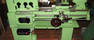
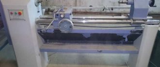
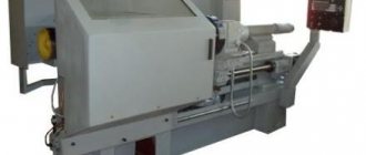
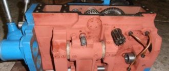
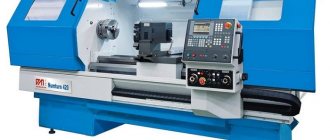
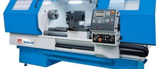
The 1A616 lathe has a long history: it began to be produced back in the mid-50s of the last century. The production of this machine, which many experts recognize even from the photo, was carried out by the Srednevolzhsky Machine Tool Plant. This model can still be found in many manufacturing plants today.
Screw-cutting lathe 1A616
Description
The 1A616 lathe is equipped with a caliper that moves in the transverse direction mechanically to a maximum value of 195 millimeters. In the longitudinal plane, the movement of the element is ensured by a screw and a roller to a maximum value of 670 mm. Feed parameters have the same range ranging from 0.065 to 0.91 revolutions per minute.
The characteristics of the machine make it possible to quickly replace gears in the feed box with replaceable precision parts. This allows threads to be cut with the highest possible precision. To cut standard threads in inch, modular or metric configurations, such a replacement is not necessary. Obtaining accurate parameters is determined by turning on the lead screw directly, bypassing the feed box.
Technical characteristics of the lathe 1A616
The unit in question is used for processing workpieces of compact sizes. The equipment has the following technical parameters:
- The turning limit along the length is 660 mm.
- The maximum length of the workpiece is 710 mm.
- The diameter of the workpiece above the support/bed is 180/320 mm.
- Weight – 1.5 tons.
- The diameter of the spindle through hole is 35 mm.
- The type of threaded tip according to GOST is 6K.
- The spindle rotation interval is 9-1800 rpm.
- Length/width/height – 2.13/1.22/1.22 m.
The following types of threads are cut on the 1A616 lathe:
- Pitch processing in steps of 2-128.
- Inch thread – 1-56 threads per inch.
- Modular version – in the range from 0.25 to 5.5 mm.
- Metric version - 0.2-24 mm.
The workpieces to be processed are placed in a conventional chuck and secured using pneumatic or hydraulic clamping devices.
Name marking
The designation of the alphanumeric index 1a616 is deciphered as follows:
- 1 – machines belonging to classification group 1 – turning;
- A – the first model that has not undergone modernization;
- 6 – machine type – screw-cutting lathe;
- 16 – limiting parameter – the height of the centers above the bed level – 165 mm.
Design
The equipment in question includes the following elements and parts:
- Front and rear cabinet.
- Front and rear headstock.
- A reversing device, a sorting device, as well as a block responsible for increasing the working step.
- Assembly of replacement wheels.
- Cabinet for electrical equipment.
- Apron with feed mechanism.
- Stanin.
- Feeding box.
- Cooling system for cutting tools.
- Gearbox.
- Tray for collecting chips and waste refrigerant.
Operating principle
Metalworking machines 1A616 operate according to the following principle:
- Before processing, the part is fixed in the equipment chuck or between centers.
- The cutters are mounted in their holder on the support. No more than four cutting elements can be installed at the same time.
- To carry out the manipulation of drilling or cutting internal threads, a suitable tool is fixed in the tailstock quill.
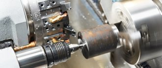
- The main processing of the workpiece is carried out through a combination of translational-rotational movement of the cutter and rotation of the part. This design allows the processing of cylindrical, conical and shaped parts, including screw and end parts.
On the 1A616 metal lathe, the transmission of torque to the spindle and the workpiece is carried out using a belt pulley, which is placed between the supports. If necessary, the V-belt can be replaced without removing the spindle. The design of this equipment provides for the principle of separate transmission to the caliper. It can be moved using a lead screw or a roller. A DC starter is used in the motor winding, providing effective braking of the drive.
Repair features
Lathe 1k62d
Almost all components of the 1A616 machine have features for disassembling and replacing elements. To avoid mistakes, work should be carried out by carefully studying the drawings contained in the equipment operating instructions. Also, a lot of information on carrying out individual repair operations can be found on special resources.
To carry out complex work, for example, replacing a dog clutch, you should strictly follow the instructions given in the documentation for the equipment. Here you will find all the data related to repairs, allowing you to adjust the bearing or configure the operation of an entire functional unit of the machine.
How to remove a cartridge
Some jobs are quite simple. In particular, removing the cartridge. It is of a cone type, fixed with four faceplate nuts on bolts. To remove this element of the assembly, just unscrew them. It is worth noting separately: in some modifications of the machine, a removable faceplate is not used; instead, a permanent chuck mounting is located on the spindle.
How to remove the faceplate
Removing the faceplate is difficult. It is screwed very tightly onto the gear shaft of the headstock, the mass of the part is quite large, so turning the connection manually is almost impossible. Disassembly experience without the use of special tools has shown the effectiveness of the following options, which require the use of gearbox gears.
- Move the chuck jaws apart and place a crowbar or a thinner piece of metal between them. Turn the spindle so that the lever is located in a position convenient for lowering with force, just above the head. Turn on the transmission gearbox to minimum speed and turn on the search. When starting to rotate, sharply pull the rod down. This operation is potentially dangerous, both due to injury and damage to the elements of the box.
- Clamp a hexagon with a spanner on it or a metal rod across the axis in the chuck. Rotate the spindle so that the end of the lever rests on the rear guide of the bed. Switch the gearbox to low speed, reverse rotation and turn on the drive. To avoid damaging the surface of the guide, it is recommended to place a board or other damper under the lever.
These methods are used for manual disassembly. However, to carry out repairs of this kind, it is recommended to invite professionals with special equipment.
Gearbox repair
If the tension of the drive belts is adjusted, the gearbox is repaired. To do this, the fastening screws are unscrewed, adjustments are made with the appropriate nut for each pulley, after which the fastening elements are installed in place.
Replacing V-belts for a twelve-speed gearbox is also not difficult. To do this, the lubrication system is partially dismantled. Remove the cap, flange, screws and supply tubes. Afterwards, screw the M12 screws into the holes provided for this until the axle box comes out of the headstock. Insert the belts onto the seam and perform all the operations performed in the reverse order.
Electrical diagram
The electrical circuit of the 1A616 lathe includes the following elements:
- Fuses.
- Switch at the entrance.
- Light element for illuminating the work area.
- Voltage relay.
- Switch-on and reverse contactors.
- Coolant pump activation regulator.
- Motor speed relay and contactor control analogue.
- Step-down transformer.
- Load level indicator.
- Rectifier.
- Equipment control unit switch.
The metalworking unit is equipped with two electric motors, each of which has its own functionality. The PA22 three-phase motor has a power of 0.12 kW and a speed of 2800 rotations per minute. It serves to turn on the refrigerant supply pump to the work area.
The three-phase analogue A02-41-4 has a power rating of 4 kW (1430 rpm). Its purpose is to ensure the operation of the main drive of the machine.
Industrial models are designed for a voltage of 380 V, household versions are combined with a 220 V electrical network. Modifications designed for 500 V are available on request.
Introduction
The purpose of the course project is to study the issues of installation, technical operation and repair of a turret lathe model 1A616.
To achieve the goal, it is necessary to solve the following tasks:
— study general information about the machine;
— consider the circuit and lubrication system;
— consider the installation process;
- calculate the foundation;
— consider measures for maintenance, operation and repair;
— calculate the category of repair complexity;
— consider issues of labor safety during operation of the machine and environmental safety of technological processes.
The working process
The feed movement during operation of metalworking machines 1A616 occurs from the spindle assembly to the support. The gearbox is able to ensure the operation of the equipment in 48 ranges, officially 22 of them are indicated, since some speeds are the same. To move the caliper longitudinally, a gear coupling is used, and in the transverse plane, a lead screw is used.
To cut threads with pitches of less than six millimeters, the caliper and spindle are directly connected to each other. Processing of large values is carried out using enumeration and an intermediate element of increasing the step. The main working movement of the equipment in question is the cutting moment performed by the spindle with the workpiece fixed in it. In addition, a pair of V-belt transmissions and a speed unit with 12 ranges are responsible for this process.
Kinematic diagram
The diagram under consideration allows us to imagine the location of all working units of the unit and their constituent mechanisms. To get acquainted with it, just look at the product passport.
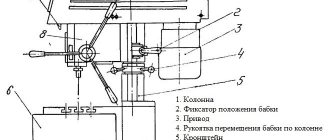
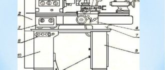
Having studied the kinematics of the 1A616 machine (figure below), any machine operator can easily understand all the intricacies of its functioning. In addition, thanks to this knowledge, it is possible to use all the capabilities of the mechanism and, if necessary, improve your skills.
Gearbox
This critical component of the lathe includes three shafts housed in bearing housings, movable bolts with gears, and a single active gear. The rotation speed is selected by meshing gears with different parameters. The dynamics are transmitted to the shaft, gears and spindle of the equipment. To increase the rotation speed of the spindle, it is connected directly to the hollow shaft using a cam-type coupling.
When operating a lathe, remember about additional mechanical (manual) manipulations. These include:
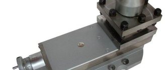
- Rotate the cutter holder and place it in the required position.
- Moving the tailstock with the quill placed.
- Installing the caliper in the required position.
Controls
Elements that include functions and movements on the machine:
- spindle speed setting handles;
- feed selection handles;
- selection of thread pitch;
- threaded screw connection;
- feed rotation direction;
- overkill;
- turning on cross feed;
- turning and clamping the tool holder;
- caliper screw;
- "Start", "Stop" buttons;
- quill clamping;
- tailstock clamp;
- tailstock extension;
- inclusion of coolant;
- power switch;
- chuck rotation reverse;
- uterine nut closing handle;
- longitudinal steering wheel;
- spindle rotation starts.
Lathe 1A616: price and reviews
The cost of the equipment in question on the secondary market, depending on the condition, configuration and year of manufacture, on the secondary market ranges from 40 thousand rubles and above.
Consumer feedback about the machine allows us to highlight the main advantages of this metalworking equipment. These users include:
- Multifunctionality.
- Reliability.
- High processing accuracy.
Among the disadvantages, owners point out that many operations must be configured manually. In addition, calibration and adjustment of equipment requires the participation of a specialist.
Product advantages
Not only skilled machine operators, but also beginners can work on machines. The design is repairable and has a large margin of safety, which eliminates quick breakdowns.
Preparing for work and setting up the operation is not difficult. Exact descriptions can be found in the operating instructions. The installation of gears on guitars and the selection is carried out according to the table.
After modernization, the 1b61a model differs from the original in the ergonomics of its appearance and the placement of electrical controls on the front side.
The main difference from 16K20 screw cutting machines is the processing of smaller products and the absence of accelerated movement.
