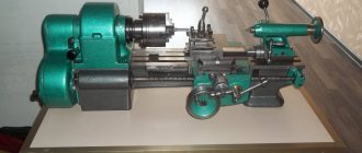
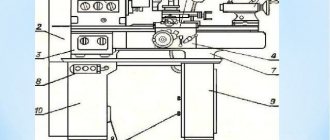
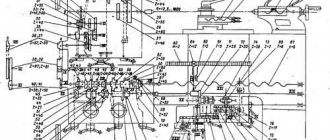
Device mechanisms
Universal lathes consist of mechanisms and standard units, which include :
- The lead screw is the main element of the device, which distinguishes it from a simple turning model.
- A box that provides change and choice of feeds.
- Device apron. It converts the rotation of the roller or screw into the translational movement of the support with the tool.
- Running roller.
- Gear guitars. This is a module that is necessary to transmit rotational motion from one machine unit to another.
- Equipment cabinets. They act as supports. Thanks to them, the main control units of the equipment and the element being processed are at a convenient height for visual inspection.
- Electrical equipment.
- The spindle is the main component of a lathe. It clamps the workpiece and rotates with it. In this case, the cutting tool moves in two independent coordinates - across and parallel to the axis of rotation. The more powerful the spindle design and its wired motor are, the higher the equipment’s performance in terms of the speed of removing metal chips from the workpiece and the more massive the elements it can process.
- Bearing frame. All equipment mechanisms are mounted on it.
- A box that provides speed control.
- Back and front headstock. The headstock is a unit of turning equipment that is necessary to rotate and support the element being processed. The tailstock is needed to support the other end of the element being processed. Can be used to install a tap, reamer, drill and other tools.
- The machine support is necessary to secure the cutting tool and transmit feed movements to it. It includes carriages - lower slides that move along the bed guides. Transverse slides move perpendicular to the axis of rotation of the element along the guides of the lower slide, on which the tool carriage and tool holder are located. The cutting carriage can be rotated to the axis of rotation of the element at different angles.
A characteristic feature of this equipment is that the structural elements of different models have the same name and location. Machines in this category, which are produced by different manufacturing plants, are almost identical in design (including those with numerical control).
To control working systems, lathes are equipped with various levers and handles. In particular, these include:
- Control element for the direction of spindle movement and its stop.
- The element that is responsible for fixing the tailstock.
- Control element for caliper movement parameters.
- Feed parameters control body.
- The steering wheel is responsible for the movement of the quill.
- An element that is responsible for automatically starting the longitudinal feed and fixing the quill.
- Switching off and on the main engine.
- A control for selecting the direction of the thread to be cut.
- Control element for turning off and on the rotation of the lead screw.
- A handle that is designed to control the upper slide.
- A control element that determines the direction of movement of the slide (transverse or longitudinal).
- The handle that is responsible for selecting the thread pitch category.
- A control element that is responsible for selecting the parameters of the thread being cut (feed or pitch).
- A handle used to change the spindle rotation speed.
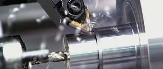
Turning principle
The operating principle of a lathe is to remove unnecessary (excess) material from the original workpiece. When processing future products, two types of movements are performed simultaneously. One of them consists of moving the cutter along the workpiece, and the second is its rotation in a special fastening device (chuck).
The first of these movements, called "feed", allows you to achieve the desired dimensions of the workpiece, as well as the shape of the boring surface. Due to the rotational movement, the required boring mode of the part is set, which allows you to achieve the required surface cleanliness. In order for various types of work on a lathe to be implemented in practice, the performer will need special tools and auxiliary equipment.
Equipment classification
The types of this equipment are divided based on several parameters, which include:
- The maximum diameter of this part.
- The maximum length of a part that can be processed on this equipment.
- Weight of equipment.
The length of the part that is processed on this equipment of one model or another completely depends on the distance between its centers. When considering the diameter of the workpiece that a certain type of lathe can process, this parameter ranges from 100 to 4 thousand millimeters. It is also necessary to take into account the fact that equipment models that can process elements of the same diameter may have different lengths of the processed workpiece.
Universal lathes can have different weights. According to this parameter, equipment is divided into the following categories:
- Lightweight machines. Their weight does not exceed 0.5 tons. It processes elements with a diameter of 100-200 millimeters.
- The weight of the equipment does not exceed 4 tons. The permissible diameter of processing elements is 250−500 millimeters.
- Equipment weight up to 15 tons. The diameter of the processed elements ranges from 600-1250 millimeters.
- The machines are heavy. Their weight can reach 400 tons. The diameter of the processed elements is 1600-4000 millimeters.
Equipment and tools
When familiarizing yourself with the technology of turning work, it is important to pay attention to the equipment used in its implementation. The main equipment of a screw-cutting lathe includes an electric motor with a set of starting capacitors and an emergency protection unit. Auxiliary devices are represented by a lighting lamp, a coolant supply mechanism and an exhaust fan.
The main toolkit of any lathe is a set of cutters used in processing. Most work operations are impossible without such names as:
- Cut-off.
- Walkthroughs.
- Threaded.
- Shaped.
- Scoring, etc.
Please note: According to the existing classification, cutters belong to the main equipment of the machine.
Auxiliary equipment includes drills and additional tools used during drilling operations. The latter are represented by the following names:
- Countersinks and countersinks used to machine the surfaces of the walls and bottoms of holes.
- Reamers that allow you to achieve high precision boring of hole walls.
- Counterbodies used for processing the bottom of sockets and grooves in the original workpieces.
This category also includes taps and dies (with their help, internal or external threads are manually cut).
Cutting tools for turning work
The efficiency of metal turning operations performed using machines is influenced by various parameters, including cutting depth and speed, and the amount of longitudinal feed. To perform high-quality processing of parts, the following conditions must be created:
- for a workpiece fixed in a chuck or faceplate, a sufficiently high rotation speed is important;
- stability and the ability to have a strong impact on the workpiece are important for the tool;
- during one pass of the tool, as much metal as possible should be cut off;
- All machine components must be sufficiently stable and maintained in working order.
The cutting speed is influenced by the characteristics of the material from which the workpiece is made, the type and quality of the cutter used. When choosing the spindle speed of a machine tool that includes a lathe chuck or faceplate, you need to focus on the desired cutting speed.
We recommend articles on metalworking
- Steel grades: classification and interpretation
- Aluminum grades and areas of their application
- Defects in metal products: causes and search methods
Different types of cutters allow for various types of rough or finishing turning work, and the choice of tools depends on the nature of the processing. By changing the geometric parameters of the cutting part of the tool, the size of the removed metal layer is adjusted. When processing a part, the right cutters move from the tailstock to the front, and the left ones, accordingly, move in the opposite direction.
Depending on the shape and location of the blades, the cutters can be:
- straight;
- bent;
- tools with an extended working part, which is smaller in width than the width of their fastening part.
There is a classification of cutters depending on the purpose of their use. They are:
- scoring (designed for processing surfaces that are located perpendicular to the axis of rotation);
- pass-through (with their help they grind flat end surfaces);
- groove (designed to form grooves);
- shaped (allowing the production of parts with a certain profile);
- boring (for boring holes in the workpiece);
- threaded (for cutting threads of any type);
- cut-off (allows you to cut parts to the required length).
The quality, accuracy and productivity of metal turning using a lathe is influenced not only by the correct choice of tool, but also by its geometric parameters. In this regard, when teaching turning, much attention is paid to the geometry of cutting tools.
Processing of surfaces of various types is carried out with cutters of a certain category in accordance with established rules:
- Using conventional straight and bent cutters, the outer surfaces of parts are processed.
- To machine an end or cylindrical surface, you will need a thrust tool.
- Grooving and cutting of workpieces is carried out using a cutting tool.
- Previously drilled holes are processed with boring cutters.
VT-metall offers services:
A separate category of turning tools is represented by cutters, which are designed for processing shaped surfaces with a generatrix line length of no more than 40 mm.
Before starting work, the turner must:
- wear special clothes, button up sleeves and jacket, check for glasses;
-receive the machine from the replacement, check whether the machine and workplace are well cleaned;
- check the presence and serviceability of the protective casing and clamping chuck, protective screen, safety devices for protection against chips, coolants;
— adjust local lighting so that the work area is sufficiently illuminated and the light does not blind the eyes;
- check the presence of lubrication of the machine; when lubrication, you should use only special devices;
- before each switching on of the machine, make sure that its start-up does not endanger anyone.
Check with the machine idling:
— serviceability of the lubrication and cooling system;
- serviceability of controls;
— serviceability of the fitting of the switching and switching levers.
Triggering of protection:
- the cartridge should stop when the casing is folded back,
- the machine should not turn on until the casing is returned to its original position;
- immediately report a machine malfunction to the foreman;
- do not start work until the malfunction is eliminated;
- work with tools, devices and materials located in a designated place, in a convenient and safe manner for use.
Work performed on lathes
Turning equipment produces parts such as rotating bodies:
- bushings;
- pulleys;
- shafts;
- rings;
- gears;
- nuts;
- couplings, etc.
To do this, mechanical processing of various surfaces is carried out, grooves are turned, drilling, countersinking, boring, threading, etc. are performed. Let's look at the features of the main types of work on a lathe.
Turning cylindrical surfaces
To process smooth cylindrical surfaces, pass-through cutters (roughing and finishing) are used in two steps. Initially, they work as rough (Fig. 1), performing rough turning.
Fig.1. Types of incisors, a – straight, b – bent, c – Chekalin’s version
After rough processing, the surface has high roughness and large scratches. To remove them, use finishing cutters (Fig. 2).
Fig.2. Types of incisors, a – normal, b – with a wide edge, c – bent, Kolesov design
Normal finishing cutters are used when turning with low feed and small cutting depth of the metal layer. A wide edge tool is used for large feeds and produces a smooth surface.
Trimming ends and ledges
For trimming, a special tool is used - a scoring cutter (Fig. 3).
Fig.3. Trimming in the centers, a – scoring cutter, b – trimming the end with a half-center
The scoring tool is used for turning the part in the centers; if you need to complete the processing of the end, you need to insert a half-center into the tailstock of the machine and perform turning in this way.
When the workpiece is fixed in the chuck at only one end, then a bent cutter can be used to process the end. To perform this procedure, as well as to grind the ledges, thrust-type scoring cutters are used. This tool can work with longitudinal and transverse feed (Fig. 4).
Fig.4. Trimming the ends with different cutters, a – bent through, b – persistent trimming
When cutting the ends, you need to make sure that the top of the cutting edge is located at the level of the centers. A tool placed above or below the centers will leave a solid, uncut lip on the end.
Grooving
Work performed on lathes for turning grooves is carried out using slotted cutters, the edge of which reproduces the shape of the desired groove. Since the width of the groove is usually small, cutters with a narrow edge are needed, which makes it quite fragile. To increase the accuracy of work with such cutters, the height of their heads is made several times greater than their width.
Grooves are also made using cutting tools that have a longer head. The length of the head is chosen based on the size of the future part; it should be 50% larger than its diameter.
Fig.5. Scoring and parting cutters
When installing a cutter (cutting, slotting) on the machine, it is necessary to maintain accuracy of installation. Misalignment during installation will cause the cutter to rub against the walls of the groove being machined - this will lead to the production of defective parts and breakage of the cutting edge.
When turning narrow grooves, one pass is made, and for wide grooves, several passes are made.
Turning cones
If you need to make an outer or inner cone on a part, use the following technique. The workpiece is mounted in the machine chuck, the upper part of the support is rotated through an angle whose value is equal to half the angle at the apex of the cone. The workpiece is turned by moving the tool using the upper slide of the caliper. This method is more suitable for turning conical elements of short length.
Fig.6. Turning cones with lateral displacement of the rear center
If you need to carve a long or shallow cone, then shift the rear center. To do this, the tailstock of the machine moves away from/toward itself to the required distance. When the workpiece is fixed in the centers in such a way that the wide area of the cone is located at the headstock of the machine, then the tailstock must be shifted away from you and vice versa.