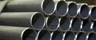
Despite the growing popularity of plastic components in the water and gas supply sector, rolled steel remains uncompetitive. The most popular among builders is the water and gas pipe - VGP.
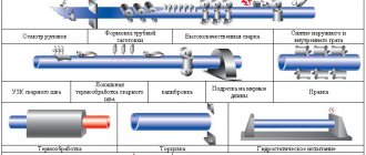
The pipe is made from a steel billet: strip, which is molded and then connected using welding. After manufacturing, the VGP pipes are tested using non-destructive testing methods.
Often, pipelines supplying gas and water are laid in conditions of high humidity, so rolled metal of this type undergoes additional processing. Products are galvanized or primed, and then coated with special paints and varnishes.
| Table of main characteristics of water and gas pipes | |||
| Drawing | Nominal diameter, d | Weight | Standard |
| from 6 mm to 150 mm | from 0.37 kg to 21.63 kg | GOST 3262-75 | |
Application
The main area of application of the VGP range is hot and cold water supply pipelines. VGP refers to a special consumable material that is used where it is necessary to maintain a high level of tightness of connections and withstand high pressure of the carrier in the line. Pressure readings can be up to 3.1 MPa.
Marking
The range of VGP pipes is marked in accordance with state regulations. Labeling may contain the following information about the product:
- accuracy class: increased (P) or normal (no designation);
- presence of thread: knurled (H), cut (P), if the product does not have a thread, no additional markings are applied;
- presence of galvanization (C);
- presence of a coupling.
Each pipe is marked if its diameter is more than 159 mm, and the batch if the diameter of each product is less than this value. Marking is applied by branding or using an electrograph.
Dimensions
When choosing pipes, two main quantities are used for correct calculation: nominal diameter and outer diameter. The first indicator is approximately equal to the internal diameter. GOST 3262-75 strictly regulates pipe sizes. For different categories of pipes, the wall thickness may vary. According to this classification, pipes are distinguished:
- Light (lightweight) - withstand hydraulic pressure up to 25 atm (2.4 MPa).
- Ordinary - withstand pressure up to 25 atm (2.4 MPa), but the walls are thicker than those of the corresponding (with the same nominal bore) lightweight pipes;
- Reinforced - withstand hydraulic pressure up to 32 atm (3.1 MPa).
| Table of sizes of water and gas pipes | ||||
| Conditional passage | Outer diameter, mm | Wall thickness, mm | ||
| lungs | ordinary | reinforced | ||
| DN 6 | 10,2 | 1,8 | 2,0 | 2,5 |
| DN 8 | 13,5 | 2,0 | 2,2 | 2,8 |
| DN 10 | 17,0 | 2,0 | 2,2 | 2,8 |
| DN 15 | 21,3 | 2,35 | — | — |
| DN 15 | 21,3 | 2,5 | 2,8 | 3,2 |
| DN 20 | 26,8 | 2,35 | — | — |
| DN 20 | 26,8 | 2,5 | 2,8 | 3,2 |
| DN 25 | 33,5 | 2,8 | 3,2 | 4,0 |
| DN 32 | 42,3 | 2,8 | 3,2 | 4,0 |
| DN 40 | 48,0 | 3,0 | 3,5 | 4,0 |
| DN 50 | 60,0 | 3,0 | 3,5 | 4,5 |
| DN 65 | 75,5 | 3,2 | 4,0 | 4,5 |
| DN 80 | 88,5 | 3,5 | 4,0 | 4,5 |
| DN 90 | 101,3 | 3,5 | 4,0 | 4,5 |
| DN 100 | 114,0 | 4,0 | 4,5 | 5,0 |
| DN 125 | 140,0 | 4,0 | 4,5 | 5,5 |
| DN 150 | 165,0 | 4,0 | 4,5 | 5,5 |
According to the standards, the wall thickness of the pipes is 2.5 - 4.5 mm, nominal diameter 6 - 155 mm, outer diameter 10 - 165 mm. Size of measured pipes: from 4 to 12 m, unmeasured: more than 12 m.
TECHNICAL REQUIREMENTS
2.1. Pipes are manufactured in accordance with the requirements of this standard and according to technological regulations approved in the prescribed manner, from steels in accordance with GOST 380-88 and GOST 1050-88 without standardization of mechanical properties and chemical composition.
Pipes for parts of water supply and gas pipeline structures are made of steel in accordance with GOST 1050-88.
2.2. At the request of the consumer, the ends of pipes to be welded, with a wall thickness of 5 mm or more, must be chamfered at an angle of 35-40° to the end of the pipe. In this case, an end ring 1 - 3 mm wide should be left.
At the request of the consumer, on ordinary and reinforced pipes with a nominal bore of more than 10 mm, threads are applied to both ends of the pipe.
2.1; 2.2. (Changed edition, Amendment No. 3, 4).
2.3. At the consumer's request, pipes are equipped with couplings manufactured in accordance with GOST 8944-75, GOST 8954-75, GOST 8965-75 and GOST 8966-75 at the rate of one coupling for each pipe.
(Changed edition, Amendment No. 3).
2.4. Cracks, spots, swellings and declines are not allowed on the surface of the pipes.
Delamination is not allowed at the ends of the pipes.
Individual dents, rippling, scratches, traces of stripping and other defects caused by the production method are allowed, if they do not take the wall thickness beyond the minimum dimensions, as well as a layer of scale that does not interfere with inspection.
On pipes made by furnace welding, it is allowed to reduce the outer diameter to 0.5 mm at the seam if there is a gentle thickening in this place along the inner diameter of no more than 1.0 mm.
(Changed edition, Amendment No. 3, 4).
2.5. At the request of the consumer, on pipes with a nominal bore of 20 mm or more, the burr on the inner surface of the pipe seam must be cut off or flattened, and the height of the burr or its traces should not exceed 0.5 mm.
At the request of the consumer, on pipes with a nominal bore of more than 15 mm, manufactured by furnace welding and hot reduction, a gentle thickening with a height of no more than 0.5 mm is allowed on the inner surface of the pipes in the weld area.
(Changed edition, Amendment No. 2, 3, 4, 5, 6).
2.6. The ends of the pipes must be cut at right angles. The bevel of the end is allowed to be no more than 2°. The remaining burrs should not exceed 0.5 mm. When removing burrs, the formation of blunting (rounding) of the ends is allowed. It is allowed to cut pipes in the mill line.
By agreement between the manufacturer and the consumer, burrs up to 1 mm are allowed on pipes with a nominal bore of 6-25 mm, manufactured by furnace welding.
(Changed edition, Amendment No. 4, 6).
2.7. Galvanized pipes must have a continuous zinc coating over the entire surface with a thickness of at least 30 microns. The absence of zinc coating on the ends and threads of pipes is allowed.
On the surface of galvanized pipes, bubbles and foreign inclusions (hardzinc, oxides, sintered mixture), and peeling of the coating from the base metal are not allowed.
Individual flux spots and traces of pipes being caught by lifting devices, roughness and minor local deposits of zinc are allowed.
It is allowed to correct individual non-galvanized areas on 0.5% of the outer surface of the pipe in accordance with GOST 9.307-89.
(Changed edition, Amendment No. 3, 4).
2.8. Pipes must withstand hydraulic pressure:
2.4 MPa (25 kgf/cm2) - pipes, ordinary and light;
3.1 MPa (32 kgf/cm2) - reinforced pipes.
At the request of the consumer, the pipes must withstand hydraulic pressure of 4.9 MPa (50 kgf/cm2)
(Changed edition, Amendment No. 2, 3, 5).
2.9. Pipes with a nominal bore up to 40 mm inclusive must withstand the bend test around a mandrel with a radius equal to 2.5 outer diameters, and with a nominal bore of 50 mm - on a mandrel with a radius equal to 3.5 outer diameters.
At the request of the consumer, pipes must withstand the distribution test:
for pipes with a nominal bore from 15 to 50 mm - no less than 7%;
for pipes with a nominal bore of 65 or more - no less than 4%.
At the request of the consumer, pipes must withstand the flattening test to a distance between the flattened surfaces equal to 2/3 of the outer diameter of the pipes.
(Changed edition, Amendment No. 2, 3, 5).
2.10. At the request of the consumer, the mechanical properties of pipes for parts of water supply and gas pipeline structures must comply with GOST 1050-88.
2.11. Pipe threads must be clean, without flaws or burrs and comply with GOST 6357-81, accuracy class B.
Pipes with cylindrical threads are used when assembling with seals.
2.10; 2.11. (Changed edition, Amendment No. 3, 4).
2.12. At the seam, blackness on the threads is allowed if the reduction in the normal height of the thread profile does not exceed 15%, and at the request of the consumer does not exceed 10%.
Threads with torn (for cut) or incomplete (for rolled) threads are allowed on threads, provided that their total length does not exceed 10% of the required thread length, and at the request of the consumer does not exceed 5%.
(Changed edition, Amendment No. 2, 3, 5).
2.13. On a thread, it is allowed to reduce the useful length of the thread (without running) up to 15% compared to that indicated in the table. 4, and at the consumer’s request up to 10%.
(Changed edition, Amendment No. 2, 3, 5).
2.14. Threading on galvanized pipes is carried out after galvanizing.
2.15. (Deleted, Amendment No. 3).
2.16. At the request of the consumer, pipe welds are subjected to testing using non-destructive methods.
(Changed edition, Amendment No. 5).
Weight of water and gas pipes
It is believed that the main parameters of pipeline products are their diameter and length. The weight of the pipes is also critical. You need to know this indicator in order to choose the right transport for transporting rolled metal. The need to calculate the strength of structures in production and determine their impact on equipment also entails the need to calculate the weight of VGP steel pipes. For the convenience of buyers, below is a table with weight indicators for the main range of rolled metal of this type.
| Weight table for water and gas pipes GOST 3262-75 | |||
| Conditional pass | Weight of 1 meter, kg | ||
| Lightweight | Ordinary | Reinforced | |
| 6 | 0,37 | 0,4 | 0,47 |
| 8 | 0,57 | 0,61 | 0,74 |
| 10 | 0,74 | 0,8 | 0,98 |
| 15 | 1,1 | — | — |
| 15 | 1,16 | 1,28 | 1,43 |
| 20 | 1,42 | — | — |
| 20 | 1,5 | 1,66 | 1,86 |
| 25 | 2,12 | 2,39 | 2,91 |
| 32 | 2,73 | 3,09 | 3,78 |
| 40 | 3,33 | 3,84 | 4,34 |
| 50 | 4,22 | 4,88 | 6,16 |
| 65 | 5,71 | 7,05 | 7,88 |
| 90 | 7,34 | 8,34 | 9,32 |
| 90 | 8,44 | 9,6 | 10,74 |
| 100 | 10,85 | 12,15 | 13,44 |
| 125 | 13,42 | 15,04 | 18,24 |
| 150 | 15,88 | 17,81 | 21,63 |
ACCEPTANCE RULES
3.1. Pipes are accepted in batches. The batch must consist of pipes of the same size, the same brand and be accompanied by one quality document in accordance with GOST 10692-80 with an addition for pipes intended for the manufacture of parts for water supply and gas pipeline structures, made of steel in accordance with GOST 1050-88: chemical composition and mechanical properties steel in accordance with the document on the quality of the billet manufacturer.
The batch weight is no more than 60 tons.
(Changed edition, Amendment No. 3, 4).
3.2. Each pipe in the batch is subjected to inspection of the surface, dimensions and curvature.
It is allowed to use statistical control methods in accordance with GOST 18242-72 with a normal level. Control plans are established by agreement between the manufacturer and the consumer.
The outer diameter of the pipes is checked at a distance of at least 15 mm from the end of the pipe.
(Changed edition, Amendment No. 3, 4, 5).
3.3. To control the parameters of the thread, to test for expansion, flattening, bending, the height of the internal burr, the remains of burrs, the right angle and the chamfer angle (for pipes with beveled edges), mechanical properties, no more than 1%, but not less than two pipes from the batch are selected, and for pipes manufactured by continuous furnace welding - two pipes per batch.
(Changed edition, Amendment No. 3, 4).
3.4. All pipes are subject to weight control.
(Changed edition, Amendment No. 3).
3.5. Each pipe is subjected to hydraulic pressure testing. With 100% quality control of the weld using non-destructive methods, hydraulic pressure testing may not be carried out. At the same time, the ability of the pipes to withstand the test hydraulic pressure is guaranteed.
(Changed edition, Amendment No. 6).
3.6. To check the thickness of the zinc coating on the outer surface and in accessible places on the inner surface, two pipes from the batch are selected.
(Changed edition, Amendment No. 2).
3.7. If unsatisfactory test results are obtained for at least one of the indicators, a repeat test is carried out on a double sample.
The results of repeated tests apply to the entire batch.
Pipe calculator
| Cost per ton with price per meter of pipe, ₽: | But |
| The price of a meter of pipe at the cost of a ton, ₽: | But |
| Total weight of 6 m of pipe, kg: | But |
| Total length 1000 kg. pipes, m.: | But |
| Name | Pipe Calculator (Round) |
| Requirements | Javascript |
| OS | Windows, Android, OSX, Linux |
| Category | Business, Education |
| Price |
Install the widget on the site
TEST METHODS
4.1. For quality control, one sample is cut from each selected pipe for each type of test.
The tensile test is carried out according to GOST 10006-80. Instead of tensile testing, it is allowed to control mechanical properties using non-destructive methods.
(Changed edition, Amendment No. 3, 6).
4.2. The surface of the pipes is inspected visually.
4.3. Hydraulic testing is carried out in accordance with GOST 3845-75 with exposure under test pressure for at least 5 s.
4.4. The bend test is carried out according to GOST 3728-78. Galvanized pipes are tested before coating.
(Changed edition, Amendment No. 3).
4.4a. The expansion test is carried out according to GOST 8694-75 on a conical mandrel with a cone angle of 6°.
It is permissible to test on a mandrel with a taper angle of 30°.
(Changed edition, Amendment No. 3, 4).
4.4b. The flattening test is carried out according to GOST 8695-75.
(Changed edition, Amendment No. 3).
4.4v. Weld inspection is carried out using non-destructive methods according to regulatory and technical documentation.
(Introduced additionally, Amendment No. 3).
4.5. The thickness of the zinc coating on the outer surface and in accessible places on the inner surface is controlled according to GOST 9.301-86 and GOST 9.302-88, as well as with devices of the MT-41NTs, MTZON or Impulse type according to the normative and technical documentation.
4.6. The thread is checked using thread ring gauges in accordance with GOST 2533-88 (third accuracy class).
In this case, the screw-in of the no-go ring gauge onto the thread should be no more than three turns.
(Changed edition, Amendment No. 3, 4).
4.7. The curvature of the pipes is controlled using a straight edge in accordance with GOST 8026-92 and a set of probes in accordance with TU 2-034-225-87.
(Changed edition, Amendment No. 3, 5).
4.8. The right angle of the pipe ends is controlled with a 90° square measuring 160x100 mm, class 3 GOST 3749-77, plate probes set 4 TU 2-034-225-87 or an inclinometer GOST 5378-88. The bevel angle of the chamfer is controlled with a protractor according to GOST 5378-88.
(Changed edition, Amendment No. 3, 6).
4.9. The outer diameter is checked using smooth micrometers in accordance with GOST 6507-90, clamp gauges in accordance with GOST 2216-84 or GOST 18360-93.
The wall thickness, the height of the internal burr and the height of the burrs are measured with a micrometer according to GOST 6507-90 or a wall gauge according to GOST 11358-89 from both ends of the pipe.
The length of the pipes is measured with a tape measure according to GOST 7502-98. Threads are controlled with gauges in accordance with GOST 2533-88.
The mass of a batch of pipes is controlled on scales of no more than 10 tons with a division value of no more than 20 kg.
(Changed edition, Amendment No. 3, 4, 5, 6).
4.10. Weld inspection is carried out using non-destructive methods according to technical documentation.
(Introduced additionally, Amendment No. 4).
Formula and calculation methods
The weight of pipes made of various metals (steel pipes, stainless steel, copper, etc.) is calculated based on the data available in the GOST and TU reference books. The weight of a meter of pipe, the range of which is not included in the directories available on the website, is calculated online using the formula m = Pi * ro * S * (D - S) * L; Pi is a mathematical constant that expresses the ratio of the circumference of a circle to its diameter, equal to
3.14; ro is the density of the metal from which the round pipe is made in kg/m³; To calculate the specific gravity of 1 linear meter of pipe (m), it is necessary to indicate the dimensions of the pipe profile: diameter D in mm, as well as the thickness of the metal from which the pipe is made (wall thickness S) and length L (default 1 m). The calculation of the theoretical weight of a rectangular profile pipe is carried out similarly to a round one, with the exception of the part of the formula for determining the cross-sectional area.
Pipe calculator
| Cost per ton with price per meter of pipe, ₽: | But |
| The price of a meter of pipe at the cost of a ton, ₽: | But |
| Total weight of 6 m of pipe, kg: | But |
| Total length 1000 kg. pipes, m.: | But |
| Name | Pipe Calculator (Round) |
| Requirements | Javascript |
| OS | Windows, Android, OSX, Linux |
| Category | Business, Education |
| Price |
Install the widget on the site
Formula and calculation methods
The weight of pipes made of various metals (steel pipes, stainless steel, copper, etc.) is calculated based on the data available in the GOST and TU reference books. The weight of a meter of pipe, the range of which is not included in the directories available on the website, is calculated online using the formula m = Pi * ro * S * (D - S) * L; Pi is a mathematical constant that expresses the ratio of the circumference of a circle to its diameter, equal to
3.14; ro is the density of the metal from which the round pipe is made in kg/m³; To calculate the specific gravity of 1 linear meter of pipe (m), it is necessary to indicate the dimensions of the pipe profile: diameter D in mm, as well as the thickness of the metal from which the pipe is made (wall thickness S) and length L (default 1 m). The calculation of the theoretical weight of a rectangular profile pipe is carried out similarly to a round one, with the exception of the part of the formula for determining the cross-sectional area.
Installation features
The assembly of pipelines from galvanized steel pipes is carried out:
- Welding connection.
- Using threads and fittings.
Given the difficulties with welding pipes, they often turn to the threaded method on fittings. I recommend using either galvanized or stainless steel connectors. This will help avoid problems with corrosion from contact of galvanized bends with simple steel parts.
Galvanized elbows with quick-release connections have appeared on sale. They are used in many industrial areas, including the laying of communications with drinking water.
As for welding, here you can use one of the options:
- Thoroughly clean the joint area from the zinc coating.
- Carry out the welding connection as usual.
- Apply a spray containing zinc to the area.