In the element base of a computer (and not only) there is one bottleneck - electrolytic capacitors. They contain an electrolyte; the electrolyte is a liquid. Therefore, heating such a capacitor leads to its failure, as the electrolyte evaporates. And heating in the system unit is a regular occurrence.
Therefore, replacing capacitors is a matter of time. More than half of the failures of motherboards in the middle and lower price categories are due to dry or swollen capacitors. Even more often, computer power supplies break down for this reason.
Since the printing on modern boards is very dense, replacing capacitors must be done very carefully. You can damage and not notice a small unframed element or break (short) tracks, the thickness and distance between which is slightly greater than the thickness of a human hair. It’s quite difficult to fix something like this later. So be careful.
So, to replace capacitors you will need a soldering iron with a thin tip with a power of 25-30 W, a piece of thick guitar string or a thick needle, soldering flux or rosin.
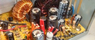
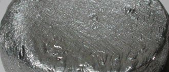
If you reverse the polarity when replacing an electrolytic capacitor or install a capacitor with a low voltage rating, it may well explode. And here's what it looks like:
So, carefully select the replacement part and install it correctly. Electrolytic capacitors are always marked with a negative terminal (usually a vertical stripe of a different color from the body color). On the printed circuit board, the hole for the negative contact is also marked (usually with black shading or solid white). The ratings are written on the capacitor body. There are several of them: voltage, capacity, tolerances and temperature.
The first two are always present, the others may be absent. Voltage: 16V (16 volts). Capacitance: 220µF (220 microfarads). These values are very important when replacing. The voltage can be chosen equal or with a higher nominal value. But the capacitance affects the charging/discharging time of the capacitor and in some cases can be important for a section of the circuit.
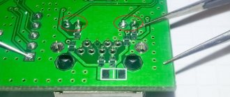
Therefore, the capacity should be selected equal to that indicated on the case. On the left in the photo below is a green swollen (or leaking) capacitor. In general, there are constant problems with these green capacitors. The most common candidates for replacement. On the right is a working capacitor, which we will solder.
The capacitor is soldered as follows: first find the legs of the capacitor on the back side of the board (for me this is the most difficult moment). Then heat one of the legs and lightly press the capacitor body from the side of the heated leg. When the solder melts, the capacitor tilts. Carry out a similar procedure with the second leg. Usually the capacitor is removed in two steps.
There is no need to rush, and there is no need to press too hard. The motherboard is not a double-sided PCB, but a multilayer one (imagine a wafer). Overdoing it can damage the contacts on the inner layers of the printed circuit board. So no fanaticism. By the way, long-term heating can also damage the board, for example, lead to peeling or tearing of the contact pad. Therefore, there is no need to press hard with a soldering iron either. We lean the soldering iron and press lightly on the capacitor.
After removing the damaged capacitor, it is necessary to make holes so that the new capacitor can be inserted freely or with little effort. For these purposes, I use a guitar string of the same thickness as the legs of the part being soldered. A sewing needle is also suitable for these purposes, but needles are now made of ordinary iron, and strings are made of steel. There is a chance that the needle will get caught in the solder and break when you try to pull it out. And the string is quite flexible and steel and solder adhere much worse than iron.
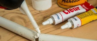
When removing capacitors, solder most often clogs the holes in the board. If you try to solder the capacitor in the same way that I advised you to solder it, you can damage the contact pad and the track leading to it. Not the end of the world, but a very undesirable occurrence. Therefore, if the holes are not clogged with solder, they simply need to be expanded. And if you do, then you need to press the end of the string or needle tightly to the hole, and on the other side of the board, lean the soldering iron against this hole. If this option is inconvenient, then the soldering iron tip should be leaned against the string almost at the base. When the solder melts, the string will fit into the hole. At this moment you need to rotate it so that it does not grab the solder.
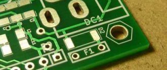
After obtaining and expanding the hole, it is necessary to remove excess solder from its edges, if any, otherwise, during soldering of the capacitor, a tin cap may form, which can solder adjacent tracks in those places where the seal is dense. Pay attention to the photo below - how close the tracks are to the holes. Soldering this is very easy, but difficult to notice, since the installed capacitor interferes with the view. Therefore, it is very advisable to remove excess solder.
If you don’t have a radio market nearby, then most likely you can only find a used capacitor for replacement. Before installation, its legs should be treated, if necessary. It is advisable to remove all solder from the legs. I usually coat the legs with flux and tin them with a clean soldering iron tip, the solder collects on the soldering iron tip. Then I scrape the legs of the capacitor with a utility knife (just in case).
That's all, actually. We insert the capacitor, lubricate the legs with flux and solder. By the way, if you use pine rosin, it is better to crush it into powder and apply it to the installation site than to dip a soldering iron in a piece of rosin. Then it will work out neatly.
Replacing a capacitor without desoldering it from the board
Repair conditions vary, and changing a capacitor on a multilayer (PC motherboard, for example) printed circuit board is not the same as changing a capacitor in a power supply (single-layer, single-sided printed circuit board). You must be extremely careful and careful. Unfortunately, not everyone was born with a soldering iron in their hands, and repairing (or trying to repair) something is very necessary.
As I already wrote in the first half of the article, most often the cause of breakdowns is capacitors. Therefore, replacing capacitors is the most common type of repair, at least in my case. Specialized workshops have special equipment for these purposes. If you don’t have it, you have to use conventional equipment (flux, solder and soldering iron). In this case, experience helps a lot.
And if there is no experience, then an attempt at repair may well end in failure. Just for such cases, I hasten to share a method for replacing capacitors without desoldering them from the printed circuit board. The method is outwardly rather inaccurate and to some extent more dangerous than the previous one, but for personal use it will do.
The main advantage of this method is that the contact pads of the board will have to be subjected to much less heat. At least twice. Printing on cheap motherboards quite often peels off due to heat. The tracks come off, and fixing this later is quite problematic.
The disadvantage of this method is that you still have to put pressure on the board, which can also lead to negative consequences. Although from my personal experience I have never had to press hard. In this case, there is every chance of soldering to the legs remaining after mechanical removal of the capacitor.
So, replacing a capacitor begins with removing the damaged part from the motherboard.
You need to place your finger on the capacitor and, with light pressure, try to swing it up and down and left and right. If the capacitor swings left and right, then the legs are located along the vertical axis (as in the photo), otherwise along the horizontal axis. You can also determine the position of the legs by the negative marker (a strip on the capacitor body indicating the negative contact).
Next, you should press the capacitor along the axis of its legs, but not sharply, but smoothly, slowly increasing the load. As a result, the leg is separated from the body, then we repeat the procedure for the second leg (press from the opposite side).
Sometimes the leg is pulled out along with the capacitor due to bad solder. In this case, you can slightly widen the resulting hole (I do this with a piece of guitar string) and insert a piece of copper wire there, preferably the same thickness as the leg.
Half the job is done, now we move directly to replacing the capacitor. It is worth noting that the solder does not stick well to the part of the leg that was inside the capacitor body and it is better to bite it off with wire cutters, leaving a small part. Then the legs of the capacitor prepared for replacement and the legs of the old capacitor are treated with solder and soldered. It is most convenient to solder the capacitor by placing it on the board at an angle of 45 degrees. Then you can easily stand him at attention.
The resulting appearance is, of course, unaesthetic, but it works and this method is much simpler and safer than the previous one in terms of heating the board with a soldering iron. Happy renovation!
In the element base of a computer (and not only) there is one bottleneck - electrolytic capacitors. They contain an electrolyte; the electrolyte is a liquid. Therefore, heating such a capacitor leads to its failure, as the electrolyte evaporates. And heating in the system unit is a regular occurrence.
Therefore, replacing capacitors is a matter of time. More than half of the failures of motherboards in the middle and lower price categories are due to dry or swollen capacitors. Even more often, computer power supplies break down for this reason.
Since the printing on modern boards is very dense, replacing capacitors must be done very carefully. You can damage and not notice a small unframed element or break (short) tracks, the thickness and distance between which is slightly greater than the thickness of a human hair. It’s quite difficult to fix something like this later. So be careful.
So, to replace capacitors you will need a soldering iron with a thin tip with a power of 25-30 W, a piece of thick guitar string or a thick needle, soldering flux or rosin.
If you reverse the polarity when replacing an electrolytic capacitor or install a capacitor with a low voltage rating, it may well explode. And here's what it looks like:
So, carefully select the replacement part and install it correctly. Electrolytic capacitors are always marked with a negative terminal (usually a vertical stripe of a different color from the body color). On the printed circuit board, the hole for the negative contact is also marked (usually with black shading or solid white). The ratings are written on the capacitor body. There are several of them: voltage, capacity, tolerances and temperature.
The first two are always present, the others may be absent. Voltage: 16V (16 volts). Capacitance: 220µF (220 microfarads). These values are very important when replacing. The voltage can be chosen equal or with a higher nominal value. But the capacitance affects the charging/discharging time of the capacitor and in some cases can be important for a section of the circuit.
Therefore, the capacity should be selected equal to that indicated on the case. On the left in the photo below is a green swollen (or leaking) capacitor. In general, there are constant problems with these green capacitors. The most common candidates for replacement. On the right is a working capacitor, which we will solder.
The capacitor is soldered as follows: first find the legs of the capacitor on the back side of the board (for me this is the most difficult moment). Then heat one of the legs and lightly press the capacitor body from the side of the heated leg. When the solder melts, the capacitor tilts. Carry out a similar procedure with the second leg. Usually the capacitor is removed in two steps.
There is no need to rush, and there is no need to press too hard. The motherboard is not a double-sided PCB, but a multilayer one (imagine a wafer). Overdoing it can damage the contacts on the inner layers of the printed circuit board. So no fanaticism. By the way, long-term heating can also damage the board, for example, lead to peeling or tearing of the contact pad. Therefore, there is no need to press hard with a soldering iron either. We lean the soldering iron and press lightly on the capacitor.
After removing the damaged capacitor, it is necessary to make holes so that the new capacitor can be inserted freely or with little effort. For these purposes, I use a guitar string of the same thickness as the legs of the part being soldered. A sewing needle is also suitable for these purposes, but needles are now made of ordinary iron, and strings are made of steel. There is a chance that the needle will get caught in the solder and break when you try to pull it out. And the string is quite flexible and steel and solder adhere much worse than iron.
When removing capacitors, solder most often clogs the holes in the board. If you try to solder the capacitor in the same way that I advised you to solder it, you can damage the contact pad and the track leading to it. Not the end of the world, but a very undesirable occurrence. Therefore, if the holes are not clogged with solder, they simply need to be expanded. And if you do, then you need to press the end of the string or needle tightly to the hole, and on the other side of the board, lean the soldering iron against this hole. If this option is inconvenient, then the soldering iron tip should be leaned against the string almost at the base. When the solder melts, the string will fit into the hole. At this moment you need to rotate it so that it does not grab the solder.
After obtaining and expanding the hole, it is necessary to remove excess solder from its edges, if any, otherwise, during soldering of the capacitor, a tin cap may form, which can solder adjacent tracks in those places where the seal is dense. Pay attention to the photo below - how close the tracks are to the holes. Soldering this is very easy, but difficult to notice, since the installed capacitor interferes with the view. Therefore, it is very advisable to remove excess solder.
If you don’t have a radio market nearby, then most likely you can only find a used capacitor for replacement. Before installation, its legs should be treated, if necessary. It is advisable to remove all solder from the legs. I usually coat the legs with flux and tin them with a clean soldering iron tip, the solder collects on the soldering iron tip. Then I scrape the legs of the capacitor with a utility knife (just in case).
That's all, actually. We insert the capacitor, lubricate the legs with flux and solder. By the way, if you use pine rosin, it is better to crush it into powder and apply it to the installation site than to dip a soldering iron in a piece of rosin. Then it will work out neatly.
KV.by
An electrolytic capacitor is a foil rolled into a tube placed in an electrolyte. But the electrolyte is special - it oxidizes the surface of the foil, forming a thin non-conducting film. One capacitor plate is foil, the other is electrolyte. Since the dielectric between the plates is extremely thin, the specific capacitance of such a capacitor is enormous. Therefore, in computers, such capacitors are used in circuits that smooth out voltage drops that occur during the operation of digital microcircuits. Everything would be wonderful, but...
Everything would be fine, but the active resistance of the electrolyte is much greater than that of the metal, so when a pulsed current passes through the capacitor, the electrolyte heats up and slowly decomposes. This leads to the fact that the active component in the equivalent circuit of the capacitor increases, and the capacitor heats up even more. This positive feedback is fatal: due to high temperature, the oxide film on the foil is destroyed in places and the capacitor begins to conduct direct electric current, completely losing its purpose. The resulting gases swell the cap of the capacitor, and from flat it becomes dome-shaped.
How does a computer react to “pregnant” electrolytic capacitors? Differently. Incomprehensible “glitches” appear when loading, or even the computer generally refuses not only to boot, but also to turn on. If such capacitors are not replaced with new ones in a timely manner, then the “pregnancy” will grow, and childbirth will be an explosion and goodbye to the “motherboard”, sometimes including the processor and memory.
Some readers may already be smiling. Of course, you can simply replace the motherboard; motherboards are not very expensive - a million or two Belarusian rubles. Why “darn a tie”? But why: it is often impossible to find exactly the same “motherboard”, and replacing it with a supposedly similar one may require reinstalling the OS. Do you need it?
There are a lot of recommendations on the Internet on how to properly resolder capacitors, but most of them are designed for the user to have a soldering station. In addition, these recommendations do not take into account some subtleties, non-compliance with which leads to a waste of time and failure.
I have extensive experience in replacing microcircuits in boards, I replaced hundreds while working at power facilities, but recently I was overtaken by the need to resolder the capacitors on the motherboard. After reading on the Internet, I ignored the recommendations and went my own way. He turned out to be simple.
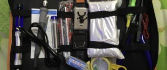
What you need for work: 1) a powerful soldering iron 60-100 W at 220 V, 2) a low-power miniature soldering iron with a conical unburnt tip at 12 V DC (sold in Zhdanovichi, costs a dollar), 3) SKF alcohol-rosin flux, 4) a little thin (0.5 mm) POS-61 solder, sold there, 4) a 17-18 V power supply, delivering at least 0.7 A DC, which will power a low-power soldering iron, 5) a brush, 6) a set of wooden toothpicks, 7) a rag for wiping soldering iron tips, ear sticks for washing off SCF residues, 9) isopropyl alcohol for washing off excess SCF. You can also use ethyl, if you don’t mind. But under no circumstances should you use acetone!
Don't worry, a low-power soldering iron will not burn out, it has double reserve, tested. Where can I get a power supply? You can make one from two old computer power supplies by connecting the 12 and 5 V outputs in series. There are a lot of old computer power supplies (not ATX) in Zhdanovichi, for half a dollar each.
Let's get to work: vacuum the computer (after all, it's already opened, isn't it?), disassemble the computer, remove the power supply, remove the motherboard, remove the memory sticks. We do not remove the processor and cooler! It will be useful as mechanical protection when you place the “mother” on the table with the back side up. Let's start with the power supply. We open it up and inspect it to see if there are any “pregnant” capacitors. If there are any, you will have to remove the power board, having first unsoldered the wires going to the 220 V power connector.
Keep in mind that 1) lead-free solder on motherboards has a melting point 30-40 degrees higher than POS-61 and 2) soldering capacitors is much more difficult than soldering new ones. Please note that one terminal of the capacitor is usually soldered to a printed conductor having a large area, and the other to a thin conductor. Therefore, a powerful soldering iron is designed for the 1st contact, let’s call it “thin”, and a low-power soldering iron is intended for the second. Let's call him "fat."
IMPORTANT! Before soldering the capacitors, be sure to check on any part of the motherboard how your soldering irons melt the solder. If they don’t melt, leave the idea.
So, let's solder it. Using a brush, lubricate the soldering area of the capacitor that we will remove. We tin the tip of a low-power soldering iron, wipe it with a rag and take a drop of solder from the solder wire onto the tip. We touch the “thin” contact of the capacitor with the tip and, when the solder melts (this will take a couple of seconds), on the other side of the board, effortlessly swing the capacitor body towards the “thick” contact. We do the same with the “thick” contact of the capacitor, but with a powerful soldering iron, and swing the body towards the “thin contact”. Then we return to the “thin” contact, then again to the “thick” one, and so on until the capacitor remains in our hands. The main thing is not to apply any force unless the solder is melted! And calm, only calm.
Now you need to clean the mounting holes from solder. This is done with a toothpick dipped in SKF, like this. We fix the “motherboard” in a vertical position using three points of support: the table top, the stomach and, excuse me, your balls. With your left hand, with a force of 50-100 g, press the toothpick into the hole to be cleaned, with your right hand, on the other side of the board, heat it with a soldering iron. Low-power – a hole for a “thin” contact, high-power – a hole for a “thick” one. When the solder has melted, insert a toothpick into the hole, twisting it a third or a quarter of a turn, and remove the soldering iron. When the solder hardens, remove the toothpick. But don't try hard. If the toothpick does not come out, touch the soldering iron to the contact pad and, when the solder on the pad melts, turn the toothpick half a turn again.
I strongly advise against cleaning the holes with a needle, as some recommend: the interlayer metallization can be torn very easily. The fact is that the needle has a thermal conductivity much higher than a wooden toothpick, and the solder immediately solidifies as the needle is inserted.
After cleaning the hole, you must immediately wash off the remnants of the SCF and carefully look through a magnifying glass from the installation side to see if there are any excess solder “snot” left that could lead to unauthorized short circuits. If there are any, then insert a clean toothpick soaked in SKF into the hole, moisten the area on the installation side with SKF and touch it for a couple of seconds with a low-power soldering iron. SCF greatly increases the surface tension of the molten solder and the “snot” usually disappears.
And yes, before unsoldering the capacitor, pay attention to the polarity in which it was installed.
Have the capacitors been soldered? We go to the Zhdanovichi radio market and buy new ones. It's time to solder. It's easy, but without skill you can make a mess. Rules: 1) when inserting a capacitor, observe the polarity, 2) when inserting a capacitor, lubricate the places for future soldering with SKF, 3) solder the “thin” contact with a low-power soldering iron, the “thick” contact with a powerful one, 4) you need to solder, giving the board a horizontal position so that the solder flows inside the metallization of the mounting hole, 5) having soldered the next capacitor, we immediately wash off the SCF, without waiting for it to “set in”, 6) take a magnifying glass and see if we have made “snot”. We correct the “snot” with a new drop of SKF and an appropriate soldering iron.
We assemble the computer and turn it on. If it doesn’t start, we go for a new motherboard.
Replacing a capacitor without desoldering it from the board
Repair conditions vary, and changing a capacitor on a multilayer (PC motherboard, for example) printed circuit board is not the same as changing a capacitor in a power supply (single-layer, single-sided printed circuit board). You must be extremely careful and careful. Unfortunately, not everyone was born with a soldering iron in their hands, and repairing (or trying to repair) something is very necessary.
As I already wrote in the first half of the article, most often the cause of breakdowns is capacitors. Therefore, replacing capacitors is the most common type of repair, at least in my case. Specialized workshops have special equipment for these purposes. If you don’t have it, you have to use conventional equipment (flux, solder and soldering iron). In this case, experience helps a lot.
And if there is no experience, then an attempt at repair may well end in failure. Just for such cases, I hasten to share a method for replacing capacitors without desoldering them from the printed circuit board. The method is outwardly rather inaccurate and to some extent more dangerous than the previous one, but for personal use it will do.
The main advantage of this method is that the contact pads of the board will have to be subjected to much less heat. At least twice. Printing on cheap motherboards quite often peels off due to heat. The tracks come off, and fixing this later is quite problematic.
The disadvantage of this method is that you still have to put pressure on the board, which can also lead to negative consequences. Although from my personal experience I have never had to press hard. In this case, there is every chance of soldering to the legs remaining after mechanical removal of the capacitor.
So, replacing a capacitor begins with removing the damaged part from the motherboard.
You need to place your finger on the capacitor and, with light pressure, try to swing it up and down and left and right. If the capacitor swings left and right, then the legs are located along the vertical axis (as in the photo), otherwise along the horizontal axis. You can also determine the position of the legs by the negative marker (a strip on the capacitor body indicating the negative contact).
Next, you should press the capacitor along the axis of its legs, but not sharply, but smoothly, slowly increasing the load. As a result, the leg is separated from the body, then we repeat the procedure for the second leg (press from the opposite side).
Sometimes the leg is pulled out along with the capacitor due to bad solder. In this case, you can slightly widen the resulting hole (I do this with a piece of guitar string) and insert a piece of copper wire there, preferably the same thickness as the leg.
Half the job is done, now we move directly to replacing the capacitor. It is worth noting that the solder does not stick well to the part of the leg that was inside the capacitor body and it is better to bite it off with wire cutters, leaving a small part. Then the legs of the capacitor prepared for replacement and the legs of the old capacitor are treated with solder and soldered. It is most convenient to solder the capacitor by placing it on the board at an angle of 45 degrees. Then you can easily stand him at attention.
The resulting appearance is, of course, unaesthetic, but it works and this method is much simpler and safer than the previous one in terms of heating the board with a soldering iron. Happy renovation!
It is believed that about half of the failures of electronic boards are associated with a malfunction of the capacitor, without replacing which the further functioning of the circuit is impossible.
These parts themselves may vary both in characteristics and dimensions; however, they all have one thing in common - the presence of the main controlled parameter (capacity).
In order to check the capacitor installed in the circuit (including the so-called “electrolytes”), it is necessary to measure its capacitance. The faulty part will have to be removed from the circuit and then soldered on with a new one. Some types of capacitors do not need to be soldered, since they are attached by welding or clamps.
Capacity check
There are several ways to check electrolytic capacitors (as well as non-electrolytic ones) to ensure they maintain their nominal capacity (capacity).
But first you need to familiarize yourself with measuring instruments that allow you to correctly estimate the capacitance value of a particular element before soldering anything.
To measure capacitors with nominal capacities up to 20 microfarads, a conventional multimeter with the appropriate function may be sufficient. An inexpensive device like DT9802A can be used as such a meter.
To assess the condition of elements with high ratings, you will need a special device such as an “RLC meter”. Using such a device, you can test not only capacitors, but also such common elements as a resistor and inductor.
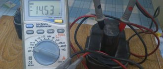
Checking the capacitor with a digital multimeter:
Often a faulty capacitor swells and is noticeable without the use of any instruments.
A simple, but not very effective method of identifying a malfunction is checking with a conventional ohmmeter, the reading of which can be used to judge the integrity of the dielectric gasket.
This method is usually used when the device does not have a capacitance measurement function. For these purposes, a simple pointer device can be used, switched to resistance measurement mode.
When the ends of the probe touch the legs of a working element, the arrow should deviate slightly and then return to a similar state.
If the readings on the device have changed, and the needle, after the deviation, has stopped at some final resistance value, this means that the capacitor is broken and must be replaced.
Check in board
One of the most common ways to check a capacitor without removing it from the circuit is to connect in parallel another, previously working capacitor with a known rating.
This method allows you to judge the serviceability of the element by the device indicator, which shows the total capacity of two parallel-connected “condensers”. When capacitors are connected in parallel, their capacitances add up.
With this approach, it is possible to do without soldering the capacitor in order to remove it from the circuit in which it is shunted by elements (resistors) connected in parallel.
However, the possibilities of using this method are limited by the permissible voltages operating in a given electronic circuit and on the board of the device under test.
The method is effective only at small potentials comparable to the maximum voltage values for which the electrolytic capacitor is designed.
How to connect capacitors to increase capacity
So, there is a parallel and series connection of capacitors. When connected in parallel, the capacitance of the capacitors is added, that is, combined. Thus, if you need to get one 7 µF capacitor, then you need to connect two, 6.8 µV and 200 nF.
When capacitors are connected in series, the total value is formed, divided by the sum. This means that there is no point in connecting large capacitors with capacitors of smaller capacity in this way. Always, the capacitors that follow each other will be approximately equal in value.
Thus, the capacitance of series-connected capacitors in the circuit does not increase, but the voltage increases significantly. Therefore, series connection of capacitors takes place where you need to get a stable circuit that can withstand high voltages.
Measurement Precautions
For those who decide to independently check the serviceability of the capacitors built into the circuit and then solder them, we recommend adhering to the following rules.
- Be sure to ensure that the circuit is completely de-energized. To do this, use the same multimeter turned on in voltage measurement mode to check that it is absent at all control points on the board.
- When measuring “suspicious” capacitors built into a circuit, you should be careful not to accidentally damage the elements connected in parallel to it.
- And finally, additionally mounted elements in the circuit must be soldered with extreme caution so as not to damage the rest of the circuit.
Only if all these conditions are met is it possible to keep the controlled device in working condition.
How to resolder a capacitor on the motherboard
Before soldering a new capacitor, you need to unsolder the old one. You should unsolder a damaged or faulty element from the motherboard as quickly as possible, so as not to overheat the contact pads, which otherwise may simply fall off.
To free the legs of the soldered element from solder, you should warm up the seat well. Only if it is sufficiently warmed up when soldering the capacitor is it possible to avoid damaging the board tracks.
When holding a small capacitor on one side, you need to try not to get burned, since its contact becomes hot when heated by a soldering iron.
In addition, you need to be as careful as possible and not use too much force, as the soldering iron tip can break off and damage adjacent parts.
The sequence of actions is as follows:
- First, turn off the power to the computer, disconnect not only the network cable, but also other power wires.
- Remove the cover and unscrew the motherboard.
- They inspect the board and find a damaged element, study its parameters (on the markings), and buy a replacement.
- Note what polarity the capacitor was connected to (you can take a photo).
- Using a soldering station or a soldering iron, the damaged capacitor is soldered out.
- Install and solder a new one.
After removing the capacitor, there remains a free space, which should first be carefully cleaned of solder residues using a suction.
Some radio amateurs use a sharpened match (toothpick) for this purpose, through which the mounting hole is pierced while simultaneously heating with the tip of the soldering iron tip.
Another way to free holes from solder residue involves drilling it out with a drill of a suitable size.
Upon completion of the preparation of the site for the new element, its legs should first be molded accordingly so that they easily fit into the mounting sockets. All that remains to be done after this is to solder it in place of the burnt one.
How to resolder capacitors on a motherboard?
Fig.1. We will change...
As a rule, there are two main reasons:
- on the quality of components.
- The manufacturer/assembler/owner of the computer itself “saved” on the case (poor quality power supply, poor cooling of components, etc.).
You can tell it simply by appearance - everything is “swollen”, with the appearance of leaked electrolyte, etc. - must be replaced. Examples can be seen in the article How to identify swollen capacitors?.
Fig.2. Soldering iron of “domestic” production 40W.
First, of course, you will need a soldering iron ( Fig. 2. ). 40 soldering iron is usually sufficient .
When using soldering irons with a power of 80 W or more, sufficient experience is required so as not to damage the printed circuit board assembly by excessive overheating (contacts, adjacent tracks, vias, etc.), therefore the use of such is not recommended .
However, it is worth noting that with a soldering iron of higher power, soldering goes faster and the quality of soldering is higher, since it is possible to heat up fairly wide conductors (Mainly ground and power buses). If the soldering iron is new, don’t forget to tin it, and if it’s old, don’t forget to smooth out the cavities.
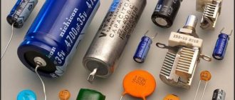
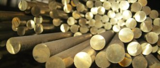
Just as you can’t fry without oil, you can’t solder without rosin or flux. The easiest way to find regular rosin ( Fig. 3. ), but you can also use flux ( Fig. 4. ) of a certain brand. In addition, it is logical that solder may be required ( Fig. 5. ) (it is more convenient to use solder that already contains rosin), although in extreme cases, in principle, nothing will prevent you from using what is already on the board.
| Fig.3. Rosin | Fig.4. Flux LTI-120 | Fig.5. Tin |
| Fig.6. We take the motherboard in one hand (soldering iron in the other)… | Fig.7. We warm up its contacts (legs) on the back side of the board... | Fig.8. At the same time, slightly rock the capacitor from side to side... | Fig.9. ...until it completely “sticks out” with such a swaying... |
Everything needs to be done with sufficient speed - if you “fry” the legs of the capacitor for a long time, which “sits” in the board on small contact tracks, they can simply fall off from the temperature. And at the same time, before pulling the part, it needs to be warmed up well, otherwise the contact tracks may come off the board. In addition, holding the capacitor with your finger, especially if it is small, can simply get burned on its body, which is hot from prolonged heating.
Soldering process
Before soldering, you need to insert the legs into the socket, observing the polarity. The negative leg of the part is usually shorter than the positive leg; it is installed on the “minus” pad (usually painted white). Soldering must be done from the reverse side; to do this, the board is turned over and the legs are bent.
Soldering the capacitor will be much easier if you first moisten the contact “spots” with a drop of flux.
The soldering iron is heated, brought to the contact pad, and the solder wire is brought to it. Use a sting to touch the solder so that a droplet slides onto the soldering site. So you need to solder all the contacts sequentially, and then bite off the extra protruding legs with pliers.
You may not be able to solder beautifully the first time, and you will need to practice. It is better to learn soldering methods in advance on unnecessary parts. After replacing the faulty element, you should try to turn on the motherboard and check its functionality.
The subtleties of good soldering
To solder a part to the board, you need:
1) Apply flux to the soldering surface; 2) Tin them with solder; 3) Apply flux to the contacts again; 4) Solder the gap between the contacts.
The first important rule is to avoid temperatures above 400°C or more. Many beginner (and even experienced) radio amateurs neglect this. These are critical values for microcircuits and boards.
Solder melts at approximately 180 to 230°C (lead-containing solders) or 180 to 250°C (lead-free). This is far from 400 °C. Why then set the temperature high?
What you need for reliable contact
Main criteria:
- Choose the right flux. For example, liquid flux is suitable for soldering wires. It wets wires best and allows for better tinning of such contacts. Low-quality flux quickly boils and spreads over the board.
- Use high quality solder. It is the solder that determines the further reliability and strength of the connection. Also, the quality of the solder can affect the operation of the circuit as a whole; due to slag and low-quality alloys, interference may occur in the operation of the electronics and, over time, cracks may appear.
- Use proven tools and equipment. Soldering irons of poor quality can maintain temperature unstably and overheat.
- Maintain temperature conditions. Do not overheat the parts and stay within the melting temperature of the solder. The temperature is too low and the solder will not melt well, and if it is too high, the material will evaporate, making it worse to tin the contacts.
- Long hours of practice, trial and error. Without practice, there will be no soldering method.
These criteria are interrelated with each other. And with a poor choice of components and materials, the same result will occur.