It is believed that about half of the failures of electronic boards are associated with a malfunction of the capacitor, without replacing which the further functioning of the circuit is impossible.
These parts themselves may vary both in characteristics and dimensions; however, they all have one thing in common - the presence of the main controlled parameter (capacity).
In order to check the capacitor installed in the circuit (including the so-called “electrolytes”), it is necessary to measure its capacitance. The faulty part will have to be removed from the circuit and then soldered on with a new one. Some types of capacitors do not need to be soldered, since they are attached by welding or clamps.
Motherboard and its functions
This is a part of the computer to which other devices of the system unit are connected. It is a multilayer board on which microcircuits and radio components, connectors and much more are located.
The main capacitors are located on the board. Their purpose is to ensure the supply of even electrical voltage. The amount of electricity your computer consumes can change dramatically. This mainly happens when you turn it on and off.
Swollen capacitors on the motherboard do not function. A sudden change in voltage can damage individual elements of the system unit. Capacitors smooth out surges, thereby increasing the stability of the equipment and extending the service life of individual elements.
Measurement Precautions
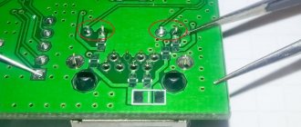
For those who decide to independently check the serviceability of the capacitors built into the circuit and then solder them, we recommend adhering to the following rules.
- Be sure to ensure that the circuit is completely de-energized. To do this, use the same multimeter turned on in voltage measurement mode to check that it is absent at all control points on the board.
- When measuring “suspicious” capacitors built into a circuit, you should be careful not to accidentally damage the elements connected in parallel to it.
- And finally, additionally mounted elements in the circuit must be soldered with extreme caution so as not to damage the rest of the circuit.
Only if all these conditions are met is it possible to keep the controlled device in working condition.
Symptoms of malfunction
Swelling of the capacitors on the motherboard causes the computer to freeze, and the following malfunctions may also occur:
- the system unit does not turn on;
- when you turn on the computer tries to start, but immediately turns off;
- The system unit turns on, but the monitor screen remains dark.
In such a situation, they usually contact a specialized service for repairs. But if the breakdown is caused by swollen capacitors on the motherboard, you can try to repair it yourself.
Minus symbol
The principle of marking the polarity of imported products differs from traditional standards of the domestic industry and consists of an algorithm: “to find out where the plus is, you first need to find where the minus is.” The location of the negative contact is indicated by both special symbols and the color of the housing.
For example, on a black cylindrical body, the negative terminal side, sometimes called the cathode, has a light gray stripe applied along the entire height of the cylinder. A dashed line, or elongated ellipses, or a minus sign, as well as 1 or 2 angle brackets with an acute angle directed towards the cathode, are printed on the strip. The model range with other denominations is distinguished by a blue body and a pale blue stripe on the side of the negative contact.
Other colors are also used for marking, following the general principle: dark body and light stripe. Such markings are never completely erased and therefore you can always confidently determine the polarity of the “electrolyte,” as electrolytic capacitors are called for brevity in radio engineering jargon.
The body of SMD containers, manufactured in the form of a metal aluminum cylinder, remains unpainted and has a natural silver color, and the segment of the round upper end is painted with an intense black, red or blue color and corresponds to the position of the negative terminal. After mounting the element on the surface of the printed circuit board, the partially painted end of the housing, indicating the polarity, is clearly visible on the diagram, since it has a greater height compared to flat elements.
The polarity designation of a cylindrical SMD device corresponding to the marking is applied to the surface of the board: this is a circle with a segment shaded with white lines where the negative contact is located. However, it should be noted that some manufacturers prefer to mark the positive contact of the device in white.
Finding faulty elements
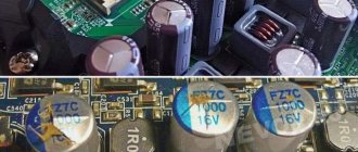
As a rule, swollen capacitors on the motherboard are of the electrolytic type. They look like cylinders and consist of thin aluminum foil twisted into several layers - the anode, placed in a liquid electrolyte - the cathode. A thin layer of oxide film acts as a dielectric.
The manufacturer applies cross-shaped notches on the upper surface of the cylinder. They allow you to visually identify a malfunction. When the capacitor on the motherboard near the processor swells, it opens like a flower or swells along the notch line.
If the seal is broken, you may notice electrolyte leaks. Corrosion of the outer coating of the part often occurs.
Capacitor markings
The marking of a capacitor, regardless of its type, contains two mandatory parameters - capacitance and rated voltage. The most common digital marking indicates the resistance value. It uses three or four digits.
Briefly, the essence of the three-digit marking: the first two digits on the left indicate the capacitance value in picofarads. The rightmost number shows how many zeros should be added to the numbers on the left. The result is obtained in picofarads. Example: 154 = 15x104 pF. On foreign-made capacitors, pF are designated as mmf.
In a four-digit code, the capacitance in picofarads is indicated by the first three digits, and the fourth indicates the number of zeros to be added. For example: 2353=235x103 pF.
To designate the capacity, alphanumeric markings containing the letter R can also be used, which indicates the location of the decimal point. For example, 0R8=0.8 pF.
On the case, the voltage value is indicated by a number followed by the letters: V, WV (which means “operating voltage”). If there is no indication of the permissible voltage, then the capacitor can only be used in low-voltage circuits.
In addition to capacitance and voltage, other characteristics of the part may be indicated on the case:
- Dielectric material. B – paper, C – mica, K – ceramics.
- Degree of protection from external influences. G – hermetically sealed design, O – pressed housing.
- Design. M – monolith, B – barrel, D – disk, C – sectional version.
- Current mode. I – pulsed, U – universal, CH – direct current only, P – alternating/direct.
Causes of malfunction
There are several reasons for swelling of capacitors on the motherboard:
- poor quality assembly at the factory;
- incorrect installation;
- incorrect choice of operating voltage.
- boiling or evaporation of the electrolyte.
Incorrect polarity detection during installation is a relatively rare occurrence. If you lack the skills, you must trust the board repair to qualified specialists.
When choosing a capacitor, you must be guided by the rule - the maximum voltage of the part may be greater, but not less than the actual voltage at the place of its installation.
The reason for the evaporation of the electrolyte can be an increase in temperature both outside the part and in the internal environment. If the temperature in the system unit case is high, you need to check the operation of the cooling system or clean the computer. The power supply may be to blame for overheating from the inside, as well as poor-quality assembly and incorrect polarity determination. Heating can occur due to violations of computer operating rules.
Properties
From the description it is clear that for direct current the capacitor is an insurmountable barrier, except in cases of dielectric breakdown. In such electrical circuits, a radio element is used to accumulate and store electricity on its electrodes. A change in voltage occurs only in cases of changes in the current parameters in the circuit. These changes can be read and acted upon by other circuit elements.
In sinusoidal current circuits, a capacitor behaves like an inductor. It passes alternating current, but cuts off the direct component, which means it can serve as an excellent filter. Such radio-electronic elements are used in feedback circuits, included in oscillatory circuit circuits, etc.
Another property is that variable capacitance can be used to shift phases. There are special starting capacitors (Fig. 5) used to start three-phase electric motors in single-phase electrical networks.
Rice. 5. Start capacitor with wires
Troubleshooting methods
After determining the cause of the breakdown, you can proceed in two ways:
- take your computer to a service center where they will replace the burnt parts;
- try to fix the problem yourself.
The second method is more complicated, but more economical. The average cost of one capacitor is from 60 to 100 rubles.
The price of repairs in specialized services depends on the region and price list. When handing over your computer for service in Moscow, on average you will have to pay:
- about 300 rubles for diagnostics;
- for parts and materials - from 120 to 200 rubles;
- for the work of a master - from 1500 to 1800 rubles.
In addition, dishonest service workers often inflate the cost of work by offering additional unnecessary services.
Parasitic parameters of capacitors
Capacitors, in addition to their main characteristics, have so-called “parasitic parameters” that distort the operating properties of the oscillating circuit. They must be taken into account when designing the circuit.
These parameters include their own resistance and inductance, which are divided into the following components:
- Electrical insulation resistance (r), which is determined by the formula: r = U/Iout, in which U is the power source voltage, Iout is the leakage current.
- Equivalent series resistance (ESR). This value depends on the electrical resistance of the material of the plates, leads, contacts between them, and losses in the dielectric layer. The ESR increases with increasing frequency of the current supplied to the storage device. In most cases, this characteristic is not important. The exception is electrolytic storage devices installed in the filters of switching power supplies.
- Equivalent series inductance - L. At low frequencies, this parameter, due to the self-inductance of the plates and leads, is not taken into account.
Parasitic parameters also include Vloss - an insignificant value expressed as a percentage, which shows how much the voltage drops immediately after the capacitor stops charging.
Minus symbol
The principle of marking the polarity of imported products differs from traditional standards of the domestic industry and consists of an algorithm: “to find out where the plus is, you first need to find where the minus is.” The location of the negative contact is indicated by both special symbols and the color of the housing.
For example, on a black cylindrical body, the negative terminal side, sometimes called the cathode, has a light gray stripe applied along the entire height of the cylinder. A dashed line, or elongated ellipses, or a minus sign, as well as 1 or 2 angle brackets with an acute angle directed towards the cathode, are printed on the strip. The model range with other denominations is distinguished by a blue body and a pale blue stripe on the side of the negative contact.
Other colors are also used for marking, following the general principle: dark body and light stripe. Such markings are never completely erased and therefore you can always confidently determine the polarity of the “electrolyte,” as electrolytic capacitors are called for brevity in radio engineering jargon.
The body of SMD containers, manufactured in the form of a metal aluminum cylinder, remains unpainted and has a natural silver color, and the segment of the round upper end is painted with an intense black, red or blue color and corresponds to the position of the negative terminal. After mounting the element on the surface of the printed circuit board, the partially painted end of the housing, indicating the polarity, is clearly visible on the diagram, since it has a greater height compared to flat elements.
The polarity designation of a cylindrical SMD device corresponding to the marking is applied to the surface of the board: this is a circle with a segment shaded with white lines where the negative contact is located. However, it should be noted that some manufacturers prefer to mark the positive contact of the device in white.