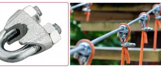
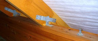
Jaw chuck for micro drills as an alternative to collet chucks
In order not to think about how to make a collet chuck or clamp with your own hands, you can purchase a jaw chuck to equip your microdrill. This clamp is an analogue of the jaw chucks used to complete conventional electric drills, and works on a similar principle. When the movable holder on the body of such a device rotates, the cams with which it is equipped move and thereby ensure reliable fixation of the tool.
Miniature jaw chuck ensures rigid fixation of working attachments
A wide variety of inexpensive jaw clamps are available today to equip micro drills. The vast majority of their models are fixed on the drive motor shaft using a threaded hole on the side of the mounting part, into which a screw is screwed. Rotation of the cam clamp cage, depending on the specific model, can be done either manually or using a special key, which is necessarily present in the factory kit of this device.
Purchasing a jaw chuck is a good opportunity for little money to equip your power tool with a universal clamping device that is easy to use and provides reliable fixation of working attachments
The main thing you should pay attention to when choosing is the material from which the main working elements of the clamp are made. If you choose a chuck whose jaws are made of durable high-carbon steel, it will last much longer and will provide precise fixation of the tool being used.
To carry out drilling work on miniature workpieces, engraving machines, the so-called “dremels,” are usually used. The name comes from the name of the most popular manufacturer. This is a convenient hand tool, but its cost is usually high (especially for high-quality branded products).
The most common area of application is amateur modeling and production of printed circuit boards. As a rule, an industrial design is redundant for such work: some of its capabilities are not in demand. Therefore, home craftsmen often create instruments with their own hands.
How to designate supports, clamps and installation devices in technological documentation.
When starting to work as a process engineer in the mechanical engineering industries, you will probably notice that on the sketches and in the operational maps of technological processes there are errors in the designation of supports, clamps and installation devices. Often these designations may be completely absent from the sketches. Indeed, there are many operations in which supports and mounting devices are not required to be specified, but this practice is not recommended.
On technological sketches, these designations serve as base indicators, and the importance of basing is difficult to overestimate. Therefore, before moving on to the concept of bases and basing in mechanical engineering, we will look at how supports, clamps and installation devices are depicted in technological documentation in accordance with GOST 3.1107-81.
Please note that to depict the designation of supports, clamps and installation devices, a solid thin line should be used in accordance with GOST 2.303-68.
Symbols of supports are given in Table 1.
Several designations of supports of the same name on the diagrams in each view can be replaced by one with a designation of their number on the right. In addition, it is allowed to depict the designation of movable, floating and adjustable supports in top and bottom views as the designation of a fixed support in similar views.
An example is a shaft installed in a three-jaw chuck, with a stop at the end and mounted in a movable rest.
The symbols for the terminals are given in Table 2.
The number of points of application of clamping forces to the product is written to the right of the clamp designation.
For double clamps, the length of the arm is set by the designer depending on the distance between the points of application of forces. A simplified graphic designation of a double clamp is allowed:
The designation of a double clamp in a front or rear view, if the points of application of forces coincide, can be depicted as the designation of a single clamp in similar views.
An example of the designation of clamps is a part installed in a jig, with emphasis on three fixed supports, and using a double clamping device (electric, pneumatic).
Symbols of installation devices are given in Table 3.
If the device is an installation-clamping device, then it is designated by a combination of designations for clamps and installation devices.
The designation of supports and installation devices, with the exception of centers, may be applied to the extension lines of the corresponding surfaces.
Reverse centers are performed in a mirror image.
Collet mandrels (chucks) should be designated
For basic mounting surfaces it is permissible to use the designation
As an example of the designation of installation devices, we can cite a part installed in a collet chuck with a mechanical clamping device, with an end stop, with a rotating center and with fastening in a movable rest.
Designations of the shapes of the working surface of supports, clamps and installation devices are given in Table 4.
Grooved, threaded, slotted, etc. the surfaces of supports, clamps and installation devices are marked in accordance with the drawing.
The designation of the shapes of the working surfaces should be placed to the left of the designation of the support, clamp or installation device.
To indicate clamping devices, designations should be used in accordance with Table 5.
The designation of the types of clamping devices is applied to the left of the designation of the clamps.
As an example of the designation of the shapes of the working surface of supports, clamps and installation devices, we can cite a part that is secured using a pneumatic clamp, with a cylindrical grooved working surface.
If the diagram has several projections, it is allowed on separate projections not to indicate the designations of supports, clamps and installation devices relative to the product, if their position is clearly determined in one projection.
Finally, the process engineer should keep in mind that deviations from the dimensions of the graphic symbols indicated in Tables 1-4 are allowed.
In this article we looked at the designation of supports, clamps and mounting devices. In the following articles we will talk about the concept of bases and basing of workpieces in mechanical engineering.
If you have questions you can ask them HERE.
List of recent articles.
- Article No. 1. Determination of numerical values of maximum deviations.
- Article No. 2. Conical inch thread with a profile angle of 60°.
- Article No. 3. How to designate supports, clamps and installation devices in technological documentation.
- Article No. 4. Basics of basing theory.
- Article No. 5. Basing. Classification of bases.
- Article No. 6. Classification of bases by deprived degrees of freedom.
- Article No. 7. Basic formulas for calculating errors in positioning and securing the workpiece.
- Article No. 8. Examples of calculating errors in positioning and securing a workpiece.
- Article No. 9. Purpose of technological bases.
- Article No. 10. Examples of tasks for assigning technological bases.
- Article No. 11. Basics of dimensional analysis. Dimensional chains.
Author: Salyakhutdinov Roman | "BOSC 8.0" Find out all the secrets of KOMPAS-3D
|
Author: Salyakhutdinov Roman | "BOSC 5.0" New Video course. "Solid and Surface Modeling in KOMPAS-3D"
|
Author: Salyakhutdinov Roman | "Work effectively in SolidWorks" Video course. “Working Effectively in SolidWorks” will help you:
|
Author: Dmitry Rodin | "AutoCAD EXPERT" Video tutorial Using AutoCAD
|
Lathe chuck: purpose, types and features of choice
Return to article list
It is difficult to imagine the rapid development of the metalworking complex without the constant improvement of machine tools. It determines the speed of sharpening parts, compliance with their geometry, and the quality of surface treatment.
To securely hold the workpiece, a lathe chuck is used to ensure the necessary clamping force and centering accuracy. This article addresses the main issues regarding the selection of devices:
This article will cover the following issues:
Lathe chucks are installed on universal and special machines and are used to fasten parts to the spindle axis. Thanks to their use, reliable fixation is achieved and the clamping force is increased with high torque. The part does not break off, maintains the correct position during operation, reducing the risk of cutter breakage and ensuring high speed of product production.
Chucks for lathes are made from hardened steel, less often cast iron, and differ from each other in design and purpose. In Russia, eight standards have been developed and approved that describe the requirements for these elements. For example, according to GOST 1654-86, there are 4 accuracy classes: A (extra high), B (high), P (increased) and N (normal).
All used lathe chucks are conventionally divided into two groups: jaw and collet. The first ones consist of several movable segments (cams), due to which the part is fixed.
They are used for most operations and differ from each other in design features and purpose.
The lathe chuck is also classified according to:
- number of cams (from two to six);
- features of fastening (on the external or internal surface);
- specifics of execution (solid, prefabricated or overhead cams);
- the drive used (manual or mechanical).
Each type of device has its own advantages, features of use and is designed for certain functions.
The 2-jaw chuck for a lathe is used for fastening complex shaped parts, non-cylindrical and asymmetrical workpieces. Their peculiarity lies in the ability to fix untreated surfaces in sponges, providing sufficient adhesion.
All parts of the product are made of steel; moving parts are subjected to heat treatment, which increases their strength characteristics and wear resistance. The dimensions are standardized: diameter varies from 125 to 400 mm. The disadvantages of devices of this type include a high risk of misalignment due to the wide gap between the guides.
Reducing time costs allows you to speed up the process, which is especially important when there is a large load, for example, on serial machines. The mechanized drive provides another important advantage: constant clamping force, due to which the part does not warp or fly out at any speed.
The mechanized drive provides another important advantage: the constancy of the clamping force, due to which the part does not warp or fly out at any speed. a - three-jaw chuck; b - four-jaw chuck
a - three-jaw chuck; b - four-jaw chuck.
The 3-jaw chuck for lathe can be either spiral or rack. Spiral structures were one of the first to appear and have been used for more than 100 years due to their simplicity and reliability.
Rapid failure is caused by the use of a fragile volute, dirt and metal shavings getting into the gaps.
Design features
Collets are made from tool and alloy steels with a hardening feature:
- the working part is hardened to the required hardness;
- the shank is tempered to the optimum value.
- Being self-clamping, the devices do not require the use of additional screws, pins or locking elements.
- Centering accuracy is ensured by elastically deformable clamping elements, called petals, moving simultaneously in the working space. This ensures their self-centering.
- The accuracy error of part centering does not exceed 0.05 – 0.08 mm.
- The forces when bending the petals should not exceed the limits of their elasticity. Hence, the requirement for the accuracy of the diameter of the part for placement in the clamping device.
- NON-STOP collet chuck Batrokhanov allows you to install and change workpieces without stopping the rotation of the spindle. The processing speed is limited by the speed that the machine bearings can withstand.
- A characteristic feature of collet devices is:
- applicability in a range of workpiece sizes, from minimal to below average;
- high cutting speed at low feeds;
- increased requirements for the accuracy of the dimensions of workpieces and tool shanks and their slight differences from the dimensions of the holes formed by the clamping blades.
Read also: How to tell if a girl is masturbating
Making a collet chuck for hand tools and machine tools
The simplest homemade collet chuck for hand tools can be created without using a lathe. If you need equipment for a machine, it will have to be machined from a workpiece and you cannot do it without special knowledge.
Method 1. The simplest wire collet
To equip a drill with low motor power, which will be used to work with wooden and plastic workpieces, a miniature collet coupling soldered from steel wire is suitable
It is important to consider that the resulting chuck can only be used for drills of the same diameter, and the diameter of the drill must correspond to the output shaft of the motor
Photo No. 2: The simplest collet clamp made of wire
For work you will need the following tools and materials:
- a cylindrical metal blank, the diameter of which coincides with the diameters of the output shaft of the motor and the drill;
- steel wire 1 mm thick;
- electric soldering iron;
- soldering flux or KFET.
The wire should be wound around a blank, forming a rigid spring. The turns of wire must be placed as close to each other as possible. The finished spring is soldered directly on the workpiece using flux or KFET.
The resulting collet coupling is put on the electric motor shaft, and a drill is inserted into the hole at the opposite end.
Method 2. Collet clamp from a screw
A collet chuck with similar characteristics can be made in another way. The product will consist of two parts connected by a screw. Fixation of the clamp on the shaft of the electric motor and the tool is ensured by cylindrical grooves on the internal surfaces of the equipment.
Photo No. 3: Blanks for making a collet clamp
To work you will need:
- 8 mm bolt or screw;
- closed nut M8;
- grinder with a metal disc;
- drill and drill bits 2 and 5 mm.
Photo No. 4: A collet chuck made from a screw mounted on an electric drill, in use
Drill a 3mm hole in the bolt leg. Make two even axial cuts crosswise with a grinder or a hacksaw. After this, drill a hole with a diameter of 2 mm in the closed nut exactly in the center. Extend it to 5mm. Round the edge of the bolt to create a cone. The finished collet chuck must be centered before use. Only in this case will it work correctly.
Method 3. Homemade collet chuck for a milling machine
A homemade collet chuck for a milling machine can be made on a lathe. For equipment you will need a steel blank (round timber with a diameter of 40 mm and a height of 70 mm). The work is carried out in two stages. First, the cartridge body is made, then the clamping nut.
Photo No. 5: Collet for a milling machine, turned on a lathe
Manufacturing of the cartridge body:
- Clamp the blank into the chuck with reverse jaws.
- Drill a through hole in it along the axis and bore it.
- Cut a M27 x 2 thread in the hole.
- Grind the outer surface of the blank.
- Trim the end that will support the base bearing surface on the spindle.
- Remove the resulting mandrel from the chuck and the three-jaw chuck from the machine and screw the mandrel onto the spindle until it stops.
- Bore the cylindrical and conical surfaces of the collet socket.
- Grind the end of the mandrel and cut a thread in it for the clamping nut.
Making a clamp nut:
- Clamp the workpiece into the reverse jaws of the three-jaw chuck.
- Drill a hole in it, bore the internal cavity.
- Grind the inner end bearing surface.
- Cut a counter thread in the nut.
- Screw the nut onto the chuck previously installed on the machine spindle.
The resulting equipment can be improved to make it easier to fix the tool. For this purpose, grooves are rolled on the side surfaces of the cartridge body and nut and grooves are made in the outer side surfaces.
How to make your own cartridge
For work on wood, soft metals and plastics, and home production of printed circuit boards, a low-power mini-drill made by yourself is suitable. The easiest way is to equip it with a ready-made mini-self-clamping mount made from a pen or pencil. But if you don’t have any at hand, it’s not at all difficult to make a mini-collet with your own hands. Required: soldering iron, 1 mm thick steel wire, solder.
Work progress:
Read also: Did the Universe have a beginning?
- a spiral is rolled from the wire with a diameter equal to the diameter of the electric motor shaft and the drill with which to work;
- the spiral is soldered, high quality connections are ensured by soldering flux or KFET;
- the spiral is put on the shaft and the mini-collet is ready.
Video about how a qualified metal turner made a self-clamping chuck with his own hands.
The question of how to make a collet clamp with your own hands is relevant for those who are engaged in jewelry making, engraving or printed circuit board manufacturing and use such equipment. It is specialists in these categories who most often encounter breakage of the collet clamp, which can be replaced with a new production model or made with their own hands.
There are several options for making a collet chuck with your own hands, each of which has certain nuances. However, no matter what method is used to make a homemade clamp, its price will compare favorably with the cost of a serial model.
Do-it-yourself drill for small jobs
The drill has long ceased to be an exclusively professional dental instrument. Today, a drill with a flexible shaft is actively used to perform small decorative work, grinding, polishing, and cutting various products.
At the same time, it should be taken into account that for high-quality work of the homemade product you will need a fairly powerful motor. So, an 18V motor from a screwdriver is perfect for powering drills. The easiest way would be to make an engraver from an old blender.
To make a drill you will need:
- Disconnect the top part of the blender from the working part;
- Using a utility knife, remove the rubber cover on the button and use a screwdriver to unscrew the bolts located under it;
- Using a screwdriver, from the side of the power cable, pry up the top cover of the case and carefully remove it;
- Remove the circuit connected to the power cable from the blender body;
- Remove the plastic part located above the rotator from the housing;
- Remove the plastic tip from the electric motor shaft;
- Measure the diameter of the shaft with a caliper (if you don’t have one, a ruler will also work for this purpose);
- Clean the electric motor housing from oil and degrease its surface using an alcohol wipe;
- Place a collet chuck of the appropriate size onto the shaft;
- Replace the power button with a push mechanism that controls both turning the device on and off;
- Assemble the blender.
Parts for making a drill can be found at a flea market.
The hand drill is ready! Such a tool will be powered via a power cable with a plug. You can power the tool with batteries, but then the batteries will have to be changed or charged from time to time.
Areas of application for collet chucks
The main structural element of a chuck with a clamping type collet is a sleeve with spring petals, the number of which can vary. Thus, for clamping workpieces whose diameter does not exceed 3 mm, chucks with three petals are used, when processing parts with a diameter of up to 80 mm - with four petals, and over 80 mm - with six. To process parts of very small diameters, clamping chucks are used, the collets in which are moved apart using special springs. In addition, there are models of collet chucks that are equipped with replaceable inserts of various sizes, selected depending on the geometric parameters of the workpiece being processed.
Clamping collets are used not only for fixing the workpieces being processed, but also for fastening the tool used in them, which can be a cutter, drill or tap. The tool shank is fixed by the clamping elements of a replaceable collet, which is held in the inside of the chuck by a special nut. This device works according to the following principle: when a nut is screwed onto a collet clamp, which is made in the shape of a reverse cone, this element is pulled into the hole in the chuck, thereby ensuring tight and reliable compression of the tool shank installed in it.
Set of collets with nut and locking ring for Sparky router
Among the advantages of collet chucks for milling cutters, which have made them very popular and in demand in the modern market, the following should be highlighted:
- simplicity of design;
- ease of use;
- high reliability of fixation of workpieces and tool shank.
In addition, collet chucks ensure minimal runout of both the tool and the workpieces that are fixed in them. This is explained by the fact that the bodies of rotation installed in such a cartridge are perfectly centered. Convenience and ease of use are also ensured by the fact that you do not need to use a special key or other additional devices to operate it.
Chuck with ER20 collet for cutters with shank diameter 8 mm
Of course, like any technical device, collet chucks also have disadvantages. The most significant is that the diameter of the workpiece or tool shank for a milling cutter directly depends on the working diameter of the collet itself. Thus, for tools and workpieces of different diameters, it is necessary to select collets of different sizes.
One of the most notable areas of application of collet-type chucks is the equipment of longitudinal turning machines, where they are used to fix the workpiece. Such machines, as a rule, process workpieces of not too significant diameter, which makes it possible to use collet-type clamping devices to fix them. Meanwhile, the collet chucks used to equip such machines differ in their design from the collet chucks used on lathe equipment. Longitudinal turning machines are often equipped with two types of collets, one of which, as mentioned above, is used to fix the workpiece being processed, and the second is used to secure the shank of the tool being used.
Device, types
Collet clamping equipment for a milling machine includes three main elements in its design:
- frame;
- collet or replaceable sleeve;
- clamping nut.
Longitudinal axial slots on the bushing form movable petals. Their number depends on the diameter of the part. The elements are connected to each other by a lock nut, which transmits pressure to the cone formed by the petals - the device is tightened by radial force. On the construction equipment market, there are replaceable collets with which cylindrical tools are secured . There are blanks in the shape of a polyhedron. The collet clamp is installed on the machine shaft, after which the master performs milling, sharpening or straightening of the parts.
Depending on the function, collets are divided into three types:
- Serving. The sleeve, made of hardened steel, is equipped with three partial cuts with spring tabs directed towards the center of the cartridge. The diameter of the hole in such a clamp is selected with the following condition: the workpiece must be tightly fixed in a stationary position, because in such a case every millimeter is important. The feed collet is equipped with replaceable inserts of different diameters . Then you can work with different-sized workpieces of any configuration.
- Clamping. It differs from the previous sample in that it has a through technological hole with two seats along the axis of the bushing. During processing, the workpiece is tightly clamped in the collet without the risk of falling out. If the master plans to process square parts, he will need a clamp with four slots, and for round and multi-faceted parts, he will need a chuck with three slots. A set of collets for any workpiece will ensure the processing of parts of any shape . The advantage of such a tool is low radial runout.
- Detachable (unclosing) secures parts of small diameter. The design of the expanding collet has springs for spreading the petals.
Each collet is designed for only one diameter, so they are suitable for working with long metal rods mounted on the router.
Thanks to the high precision of fasteners, taps, a turning cutter or replaceable tips for screwing nuts can be attached to the collet.
The chuck is indispensable if you need to secure a drill in a manual hammer drill or drilling machine. The clamp has a polished inner surface; at the moment of fixation, deformation of the workpiece is eliminated.
In addition to machine tools, collets are used to secure replaceable parts on hand tools. Along with standard devices, there are analogues for installation on mini-drills. In carpentry workshops you can find mechanical tools with collets connecting the working part to the handle. The miniature chuck allows, if necessary, to change the shafts of files or screwdrivers . This principle is inherent in the manufacture of mechanical pencils with replaceable graphite rods. By pressing a button, the user extends a small collet, the petals open, and the rod extends to the specified length.
Advantages and disadvantages
Among the advantages of the device are:
- ease of fixation of the workpiece and its equally easy dismantling;
- possibility of securing miniature workpieces;
- long service life, which depends on the material (hardened or cementitious steel);
- no scrolling of the workpiece due to the large contact area;
- zero radial runout, ensured by good alignment of the part in the bushing. In this way, it is possible to achieve high precision of the process.
- Its versatility makes it possible to use the collet mount on all types of machines.
The only drawback of the collet is that each individual sample fixes a part of the same diameter . For example, a 12 mm collet will only fit a drill of the same size. This problem can be solved by purchasing a set of replacement clamps to match them to workpieces of all diameters and configurations. There is an adapter cylindrical sleeve that is installed in a chuck of the required size, and the workpiece is inserted into it. The clamping nut secures the collet, and it clamps the adapter sleeve to the part. A self-clamping chuck with a set of replaceable clamps or adapter sleeves guarantees high-quality and safe operation on any machine.
Types and features
Depending on the area of application and the design features of the mechanism, collet chucks are divided into several types:
- ER collets. With two clamping points and a through hole, the most commonly used type;
- for taps. With a square groove compensating the axis;
- through and blind. The former process parts of unlimited length, the latter are suitable for workpieces of limited size, for example, workpieces in which one end is sealed;
- with one and two clamping sections. The second type, compared to the first, fixes the part more reliably by holding it at two points on the axis.
Collet chuck clamps come in two types:
- clamping The bushing is made in the form of several springy petals corresponding to the size of the fastener. The three-lobe bushing is designed for processing workpieces with a diameter of up to 0.3 cm, four-lobe bushings - from 0.3 to 8 cm, six-lobe bushings - for parts more than 8 cm in diameter;
- servers. The steel collet is equipped with three longitudinal grooves, forming petals with converging ends. The well-springing design feature allows for easy installation and reliable holding of a workpiece of the required diameter in the chuck. During operation, the feed mechanism with the screwed collet begins to move, which contributes to an even closer approach of the petals.
The feeding type of cartridge is more reliable, but requires a special key for fixation. Clamping types are used in cases where frequent replacement of cutters during operation is necessary.
DIY hand drill: manufacturing instructions
A small electric drill is a must-have for anyone who makes electronic crafts or does delicate decorative work. This machine is ideal for performing small work on wood, plastic and metal, and drilling printed circuit boards.
The motor can be taken from a hair dryer or grinder. An electric motor from a VCR or a motor from an old cassette recorder are also suitable for making crafts.
To make an electric mini drill you need:
- Connect the cartridge to the motor. This is best done using cold welding. But you need to work quickly and carefully: the weld quickly hardens and becomes as strong as iron. If it fails, it will not be possible to redo the connection.
- Place the cartridge in the jar. For better fixation, the cartridge must be treated with hot glue.
- Make a hole in the second base for the switch. It’s better if the switch is small and keyboard-based.
The hand micro drill is ready! All that remains is to solder the wires from the motor and power to the switch, observing the polarity. To power the mini-drill, 9-12v batteries will be enough. Additionally, you can do reverse on a six-pin switch.
Device manufacturing algorithm
The collection takes place in 3 stages. Let's take a closer look at each of them.
Making a mini cartridge
In order to assemble a mini drill chuck, you need to purchase a collet - a special mechanism designed for clamping cylindrical objects. Next, you need to connect the motor to the contacts of the future battery, which will power the device during operation.
If your drill is spinning in the wrong direction, swap the wire contacts.
Finding a drill of the right size is not difficult. Insert the drill into the collet body and clamp tightly. Next, the finished nozzle must be installed on the motor body. The collet should fit tightly onto the motor shaft. Otherwise, you cannot avoid vibration. The chuck for a homemade mini drill is ready.
Attachments for a homemade mini drill
can be purchased at any hardware store. Before purchasing, make sure they match the diameter of the collet.
Preparing the body
As a housing for the future device, you can use either an antiperspirant container or a regular hollow tube of a suitable size. hollow tube as the body
.
it is necessary to cut off the bottom and insert a rubber or other plug in its place. If you are making a device from an antiperspirant body
. a hole must be drilled in the cover for the drill to exit.
Connecting the elements
The motor must be installed on the reverse side. If your motor is not the right size, choose another tube. The fit must be very tight to avoid vibration as the shaft rotates. After this, it is enough to tighten the bolts on the collet and connect the resulting device to the electrical network.
One of the main disadvantages of assembling a drill with your own hands from a motor is the lower power compared to a standard device and the low strength of the drill.
If your work requires a cutter, you can easily make one yourself from an old lighter.
To do this, remove the spinning drum from the lighter and place it on a bolt of a suitable size. Secure this with a nut and insert it into the collet hole. The cutter for surface treatment is ready!
If for some reason the cartridge does not fit in size
to the cylindrical shaft of the motor or coil, it is necessary to degrease it well and then attach it to hot glue. This will help to obtain a stable and durable structure.
Such a mini drill with purchased attachments can perform minor repairs on technical equipment, drilling plastic, thin metal, and making crafts.
The problem of consumption or lack of collet cartridges is especially familiar to jewelers. Specialists involved in the manufacture of printed circuit boards also face this problem.
Collet chucks can be created independently from available materials. However, there are some nuances that will be covered in detail in the article below.
It should be noted right away that a hastily made collet will not be dismountable. That is, strictly speaking, removing one drill from it and inserting another will not work. For this reason, the manufacturing method is more suitable for those who need to create a large number of identical holes.
So, to create a homemade collet chuck we will need:
- drill;
- blank;
- steel wire;
- soldering flux;
- hoop.
Initially, you should wind the steel wire around the blank in the form of a rigid spring (the half rings come as close to each other as possible). Next, the resulting structure must be thoroughly soldered.
Today, anyone can easily purchase a special cam for any type of drill. This can be done both in construction boutiques that offer equipment for sale, and on the Internet (at auctions such as Ebay or Amazon).
The price of such a device does not exceed sixty rubles. Purchasing a cam will forever save you from searching for suitable collets for using various drills.
Of course, it is better to purchase a cam made of high-carbon, durable steel. To tighten it, it is recommended to use a special wrench, which is included in the kit.
Types and principles of operation of chucks
Collet chucks are used mainly when processing cold-rolled rods or other metal products that have an already machined surface.
Structurally, cartridges can be classified according to functionality:
- with a fixed mechanism;
- with retractable mechanism;
- with retractable mechanism.
Each design has its own characteristics. The feeding type is made in the form of a steel sleeve with 3 cuts forming petals that have a springing effect.
Type F
Collets type F - clamping the main spindle are used to secure the workpiece.
Type LN
Collets type LN - counter spindle are produced elongated, size E depends on the standard size.
Type R
Type R – are pull-type collets.
Type T
Type T - clamping.
Drawing No. 5 collet BF
Type BF
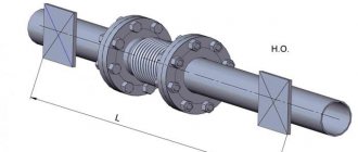
BF type feed collet - designed for bar feeding.
When installed on the machine, the feed collet is threaded onto the pipe with the help of which it is fed into the working area. It is necessary to take into account the design feature - the size and shape of the collet, which must necessarily correspond to the profile of the bar being processed.
In preparation for processing, the rod moves through the petals, which, due to their design features, tightly hold the workpiece. During processing, when feeding the workpiece, the adhesion force between the petals and the product increases due to rotation. The principle of operation of the clamping elements is based on strengthening the adhesion of the petals to the workpiece during rotation of the working mechanism. Bushings with 3 petals are used for processing products up to 3 mm, four – up to 80 mm, six – over 80 mm. Typically, collets have an angle at the apex of the cone equal to 30º.
Collets for shaft 2 mm (0.1-3 mm) for micro drill
When processing thin rods, collets equipped with springs are used to increase the clamping force of the jaws. When increasing the diameter of the workpiece being processed, designs are used that are equipped with special inserts selected according to the dimensions of the product. Collet clamps are also used when machining with a drill, cutter or tap. The sleeve is fixed in the chuck with a nut, and the cutting tool is fixed directly in the collet. When fixed with a nut, the internal volume of the hole where the workpiece is installed is reduced, thereby increasing the force holding the rod stationary.
Cartridges of this design also have their drawbacks. First of all, the requirement that the shanks of the tool used must match the characteristics of the collets used. At enterprises, the most widely used collets are the ER type, which constitute the largest number in the total volume of tools used.
When performing complex work on the manufacture of products, various collets are used, indicating all sizes and technology for performing work operations, but often it is necessary to combine equipment or make the necessary collet chuck with the required characteristics with your own hands.
Video review of a lathe collet chuck
Working principle of the collet chuck
Chucks with a set of replaceable collets are used for fastening axial workpieces and cutters on milling, lathe, drilling machines, and computer numerical control (CNC) equipment. There are many sizes and types of collet chucks that all work on the same principle. The self-clamping nut applies pressure to the end of the collet, which moves into the conical opening; its diameter decreases due to compression, firmly holding the tail end of the Morse cutter. To remove the cutter or part, the nut is screwed together, the pressure is reduced and the collet is released.
The advantage of collet chucks over others is the small radial runout of the workpiece installed in such a clamping device. Fixed in a self-clamping chuck, the part is perfectly centered. Unlike quick-release drills (QCLs) used in drills, self-clamping drills operate without keys, which are often lost.
Typically, such fasteners are used for processing bushings, cylindrical parts with a Morse shank, and rods. They are very convenient for secondary fastening of already processed parts. If the profile of the part does not match the shape of the cartridge inlet, replaceable cartridges from the kit are used.
Do-it-yourself flexible shaft for a drill
If you need to transfer the rotation of the motor of an engraver, drill or bur to an attachment, then you will need a flexible shaft. This device consists of a wire enclosed in flexible armor, twisted in several layers, and
can significantly expand the functionality of a rotary instrument. You can assemble the flexible shaft yourself.
For this you will need:
- Brass tube;
- Two M4 threaded bushings;
- Electrode shaft (diameter 5 mm) with M5 thread;
- Adapter from internal thread M5 and external thread M8 to 0.75;
- Mini quick-release chuck;
- Clamp made from an M12 bolt drilled along the axis;
- Protection for connection.
Assembling the flexible shaft. To do this, insert an electrode shaft into the brass tube and put M4 bushings on both sides of the tube. On one side of the tube we screw an adapter onto the sleeve, and onto it a mini-cartridge. On the back side of the tube we place a clamp, with which we connect the shaft from the electrode to the flexible one. For convenience, you can sand down the heads of the screws on the clamp. We put a special brass protection on the clamp and secure it with fasteners. We isolate the connection. The flexible shaft is ready! For convenience, a clamp with a plastic handle can be placed on the cartridge side.
Read also: Electric heating scheme in a private house