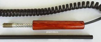
Li-ion 18650 batteries are very widely used in many of the electronic devices we use today. For example, LED lights, laptop batteries, electric bicycles or Power Bank.
These batteries are a reliable source of power, so they are also very convenient to use in DIY projects. The shape of 18650 lithium-ion batteries resembles a AA battery, but the output voltage is 3.7 V with a capacity of 1600 to 3600 mAh (AA or AAA batteries have a voltage of 1.5 V/1.2 V).
However, at the moment, charging these batteries is still not an easy matter as commercial chargers are quite expensive. In addition, lithium-ion batteries require a good quality charger, otherwise the battery life will be degraded. A balanced charger works well, but it is available at a higher price range.
So in this tutorial we decided to make a Li-Ion charger that can charge four 18650s at the same time. This charger is very easy to make and does the job of a balanced charger by cutting off power to individual batteries once fully charged.
DIY powerbank
Top
- To make a USB charger we will need:
- USB extension cable (any length, even 5-10 cm),
- cartridge for 4 AA batteries (bought on the market),
- diode (taken from a dead power supply),
- soldering iron, some flux and solder (for 30 minutes),
- multimeter (for 30 minutes),
- sealant or thick glue.
Manufacturing principle.
From the USB extension cable we leave only a socket with wires. It needs to be attached (for example, glued) to the cartridge body, and the wires coming from the [+5 VSB] and [GND] contacts of the USB socket must be soldered to the [+] and [-] pads of the cartridge
respectively.
- Cartridge for 4 AA batteries:
In a correct USB cable, the [+5 VSB] and [GND] pins are located at the edges of the connector, as indicated in the diagram. Typically the [+5 VSB] pin has a red wire and the [GND] pin has a black wire. But to check, it doesn’t hurt to put the cut-off plug into the computer and measure the potentials with a multimeter. This option
the most reliable, because the Chinese sometimes screw this up...
To prevent reverse current, when charging occurs not in the forward direction, but in the opposite direction, we place a diode in the gap of one of the wires.
It is not required, but there are also devices that can remove 5 Volts from the charger connector (for example, some models of old Sony Ericsson).
In this case, if the cartridge contains dead batteries or accumulators, physics will try to equalize the potentials on the cartridge and the phone terminals. For
In such cases, a diode is needed.
To increase the strength of the connection, I wound the socket to the cartridge with steel wire, and filled the wires, diode and gaps with hot glue. This way, dirt will not get clogged, and the wires will not accidentally get caught on any protruding objects - after all, the operating conditions of the universal charger require placement on branches, backpacks, in tents and kayaks, etc. IN
What is a protection board?
Schemes for protecting lithium batteries from overdischarge were discussed in this article.
The protection board (or PCB - power control board) is designed to protect against short circuit, overcharge and overdischarge of the lithium battery. As a rule, overheating protection is also built into the protection modules.
Read also: Collocations with the word “simple”
For safety reasons, it is prohibited to use lithium batteries in household appliances unless they have a built-in protection board. That's why all cell phone batteries always have a PCB board. The battery output terminals are located directly on the board:
These boards use a six-legged charge controller on a specialized microcontroller DW01 (JW01, JW11, K091, G2J, G3J, S8210, S8261, NE57600 and other analogues). The task of this controller is to disconnect the battery from the load when the battery is completely discharged and disconnect the battery from charging when it reaches 4.25V.
Here, for example, is a diagram of the BP-6M battery protection board that was supplied with old Nokia phones:
how to make a battery from AA batteries
How to charge a AA battery without charging - YouTube
HOW TO CHARGE A MOBILE PHONE WITH BATTERIES
how to make a battery out of batteries - YouTube
TOP 10 unusual batteries and accumulators | BATTERY-INDUSTRY.RU
Homemade battery for uninterruptible power supply from AA
How to charge batteries at home without a charger
RCView
How to charge batteries at home without a charger
How to charge any batteries using ONE charger...
A box for batteries, and a remake of a previous purchase from its ...
A box for batteries, and a remake of a previous purchase from its ...
A box for batteries, and a remake of a previous purchase from its ...
replacing batteries - YouTube
How can you restore AA batteries?
How to charge a AA battery at home?
Homemade charger for 18650 batteries for 2 slots...
How to make a charger for AAA batteries with your own hands in...
About batteries and accumulators. Educational program for humanists.
Charging AA batteries
Which AA/AAA batteries and charger to choose in 2019...
Reader tip: how to use a small AAA battery...
Portable Battery Charger | Master Class …
Repair of charger for AA batteries
Homemade charger for AA batteries with discharge function
How to properly charge a lithium-ion battery: how to assemble...
How to get 12 volts » School for an electrician: all about...
Homemade charger for AA batteries
We charge your phone using AA batteries in 15 minutes...
Chargers for AA batteries
Portable Battery Charger | Master Class …
HOW TO RECOVER A u2014 BATTERY restoration...
AA Charger | Let's create after work
How to choose a charger for batteries (Ni-Mh, Ni-Cd and Li...
How to make a battery from a capacitor with your own hands at home...
18650 battery: how to charge Li-Ion batteries of this type
We charge your phone using AA batteries in 15 minutes...
Sofirn batteries - rechargeable AA batteries - Reviews...
A box for batteries, and a remake of a previous purchase from its ...
Blog - Choosing the best battery charger
How to extend battery life???? how to charge AA batteries in...
Blog - How to choose the right AA batteries
How to charge a smartphone with three batteries and foil
Types of batteries and their characteristics
HOW TO QUICKLY MAKE A FOAM BATTERY FROM A PINKY BATTERY - YouTube
How to charge a battery at home: 6 working methods
How to charge batteries at home without a charger
How a battery explodes (+ video)
HOW TO RECOVER A u2014 BATTERY restoration...
We choose batteries: rechargeable, AA and other types
4x4 car and modification of its power supply
The simplest solar charger for AA batteries
How to choose a charger for AA and AAA batteries | Which …
The best AA and AAA batteries and accumulators and chargers for them...
Why can't simple batteries be charged like batteries? | Question …
A box for batteries, and a remake of a previous purchase from its ...
How to properly charge batteries | Electrician
Boxing (case, case) Panasonic Eneloop for AA/AAA batteries...
Methods for charging NiMH batteries and operating principles of “smart” chargers...
how to make a battery for a phone from a rechargeable AA battery???
Battery charger for cell phone or player
Camping USB charger for AA batteries | magazine
Homemade charger for AA batteries circuit diagram
How to make an economical LED flashlight using one battery...
About batteries and accumulators. Educational program for humanists.
DIY power bank
Batteries and accumulators for extreme conditions - how to choose and...
Chargers for AA batteries
Why do you need to recycle batteries?
Add a link to a discussion of the article on the forum
RadioKot >Schemes >Power >Chargers >
| Article tags: | Add a tag |
Simple charger for AA battery
Author: AcousticManiac Published 04/18/2013 Created using KotoEd.
Good afternoon everyone, today I will tell you the story of my search and acquisition of one useful scheme. It all started in the summer of 2011, when I bought an inexpensive MP3 player, an Explay L12 flash drive, plugged into USB and powered with a single little finger. I bought it in principle for my little finger, because I’m not satisfied with the insignificant period of serviceability of equipment with a built-in Li-Ion/Li-Po battery, which there’s nowhere to even recharge on the way in case of an unexpected landing, but how good it is, my little finger died - I threw it out and put in a spare tire - and listen for two more weeks (jokes aside, it really lasts two weeks on Duracell or Energizer). At first I did just that - I used galvanizing, fortunately my mother, who very usefully works on household goods, supplied me with high-quality and inexpensive energy resources. But then I wanted to switch to a NiMH battery, let me go, I think my mother is better at selling batteries than giving them to me, maybe there will be more money in the house)). Buying a little finger turned out to be no problem, but finding a charger was surprisingly difficult. The fact is that most commercially available chargers charge two to four fingers, but flatly refuse to work with one. I know there are single-channel chargers, but I couldn’t find one. And I began to scour the Internet in search of a circuit, preferably operating from 5V. USB, at the same time attracting local forum members to the search, opening a thread asking for help, and my joy was great when I found this:
But the joy was short-lived. After assembly, it turned out that it doesn’t want to work at all - the small transistor and op-amp get hot, the output voltage is not adjustable, in general, it’s terrible. My mustache drooped, and I, washing down Whiskas with valerian, complained publicly, saying, “I’m not shy, what should I do?” In response, one kind person said to me, they say, the op-amp is not suitable here, and in general, the circuit is messed up - a small transistor is superfluous, the indicators are placed in the wrong place, and blah blah blah. In general, as a result of reasoning and experiments, the following scheme was born:
It should act (and, presumably, it does) in the following way: as long as the voltage at the non-inverting input is greater than the voltage at the inverting input, the op-amp keeps the transistor open. As it charges, the voltage at the non-inverting input decreases, and as soon as it equals the voltage at the inverting input, the op-amp slams the door on the base of the transistor, closing it. The charge, however, does not stop instantly, but gradually, starting with a certain decrease in the voltage at the non-inverting input. Visually, this can be observed by the decrease in the brightness of the HL1 glow until it goes out completely even in pitch darkness, this will be the official and unconditional end of charging. The charge current depends on the resistance R2; at 15 Ohms, the charge current turned out to be ~190 mA. The power of this resistor should be better than at least 2 W, because even with my insignificant current it heats up quite noticeably (about 0.5 W is dissipated on it). Adjustment comes down to adjusting the end-of-charge voltage. To do this, instead of a battery, we insert a 100 Ohm resistor into the socket and use the R6 trimmer to set the voltage at the terminals to around 1.45-1.47 V.. Have you set the voltage? Well done, now you can insert your finger and plug the charger into the power source. Both LEDs will light up, and if HL2 lights up constantly, since it only indicates the presence of power, then HL1, as already mentioned, will indicate by its extinction that the charge is finished). Well, about setting the current has already been said. I will only add that in the attached file with seals I duplicated R2 and introduced a switch to set different magnitudes of current with different resistances. A few details: In addition to the need for a powerful current-setting resistor, this circuit requires ultra-bright LEDs. This choice is due to their high efficiency - even at a current of only 1 mA, they burn very noticeably, unlike simple AL307s, which at such a current can only be seen in the dark. And even when powered by USB, every milliamp counts. In the case of HL1, there is also no need to take too much current from the output of the op-amp, although, in principle, these AL307s do not eat that much.. In general, you can install any 3-volt lights, but for ordinary AL307s, you may have to decrease R1 and R7 to increase brightness. I used 3mm super bright red HL1 and green HL2. I also used AL307 during experiments, but the super-bright ones sank into my soul more. It is much better to take a multi-turn trimmer, because with a simple and precise setting of tension it is difficult, and the tuning can be lost from any accidental touch. You can take a transistor with any letter. I don’t even know about op-amps other than those indicated, few op-amps work from such a low voltage, and there’s no need to look for replacements, designated LM358 and LM324 like dirt everywhere. On an old motherboard, for example, you can find both (though in an SMD SOIC8 package). Some subtleties of operation: And now a little about the sad. Since the circuit is extremely simple, it is not smart enough to charge batteries with high current. As you know, the standard charge current for any battery is numerically equal to 10% of its capacity, and the charge lasts up to 16 hours. By doubling the current, we cut the charge in half. Triple-triple. The inversely proportional relationship rules. However, at high current, the battery voltage will increase faster, and the circuit will stop charging until the finger is completely restored. It’s no good to charge batteries incompletely, comrades, and therefore I recommend not setting the current to more than 20% of the capacity, but better, 10-15%, as they say, the quieter you go, the further you’ll be, and what’s the hurry - stick it in the evening and pick it up in the morning when it’s ready. Personally, that's what I do. The second unpleasant point is that if someone wants to charge 2 or more fingers from USB, they will have to assemble one circuit for each battery, and each charger will require its own portion of current; from USB 2.0, with the output current limit of 500 mA, you won’t get much use and will not set a high charge current to all fingers. The voltage at the end of the charge depends on the exact value of the supply voltage; nevertheless, in the original circuit there was a grain of truth in the form of a stabilizer) So the charger must always be driven from the same power source. I use a 5V AC adapter with a USB connector that I left over from another old player. I would like to express my gratitude to my comrade under the nickname Sstvov for bringing the diagram to a working form, and to our respected moderator Starichok51 for useful advice and explanation of the principle of operation of the scheme. Thanks to their help, I can now share this small useful thing with humanity))) And I apologize for the many books, I just wanted to describe everything down to the smallest detail)) Well, in conclusion, a couple of photos - a two-channel prototype assembled for the final tests (they passed successfully), and a single-channel final version, which has been providing my player with inexhaustible renewable energy for almost a year and a half.
Files:
RAR archive
All questions in the Forum.
| What do you think of this article? | Did this device work for you? | |
| 106 | 4 | 7 |
| 1 | 0 |
Discharge mode
If at the start of the program the voltage on the battery is below Umax, the battery is recharged with a current Is. After reaching the voltage Umax, the discharge of the battery with current Ii begins. The battery capacity is being calculated.
When the voltage on the battery reaches Umin, the discharge stops, the indicator displays the discharge off and the capacity on the battery -???.?AH Vm 11.0 – the minimum voltage on the battery.
If the recharging or discharging time has expired (time H is set for recharging and charging), the program stops, ERROR is displayed.
If the charge or discharge current exceeds the set value by 0.2, the program stops, ERROR is indicated in the top line. In the bottom line is the current at which the shutdown occurred.
Built-in controller
Thanks to technological progress, the comfort of servicing and driving a car increases. Many modern cars are equipped with on-board computers. One of its functions is to display battery voltage. But such luxury is not available to all drivers. Older models sometimes have an analog voltmeter installed, but it is difficult to judge the charging status from its readings. Therefore, they began to produce special batteries. They are available either built into the battery or as separate devices that connect to the on-board computer.
Batteries are usually equipped with built-in indicators. They are float indicators, often called hydrometers. By their color you can determine the degree of charge of the battery and the electrolyte level. To monitor the battery condition, a single cell indication is sufficient. Before using the indicator, you should lightly tap it. This is necessary to remove air bubbles that may interfere with observations. This way you can clearly see the color of the indicator.
When analyzing, it should be taken into account that when the battery begins to charge, the density of the electrolyte increases closer to the electrodes. Above the electrodes, the increase in density occurs due to diffusion. The indicator is located above the electrodes and will react accordingly to the density in this part of the battery. This may cause inaccurate results.
Even when fully charged, the indicator may remain black. This situation is explained by the fact that the electrolyte layers of higher density did not have time to mix with layers of lower density. The diffusion process can last several days.
The built-in indicator circuit looks like this:
Battery hydrometer design
Operating principle
Most hydrometers have the same operating principle; it is based on three indicator positions. As the battery charges, the density of the electrolyte increases. Thanks to this, the green ball, which acts as a float, floats up the tube and appears in the indicator eye. Usually the float is visible if the battery charge is above 65%.
Green float visible
If the float sinks in the electrolyte, this means that the density is not normal and the battery is not charged enough. In this case, the indicator eye will be black. This situation indicates that recharging is necessary.
Black eye
There are models in which, in addition to the green ball, there is a red one that rises through the tube at low density. In this case, a red ball will be visible in the eye.
The last option is low electrolyte levels. In this case, the electrolyte surface will be visible through the indicator eye. This means that it is necessary to add electrolyte or distilled water. However, in the case of a maintenance-free device, this is difficult to do.
Liquid surface visible
PI or UPS?
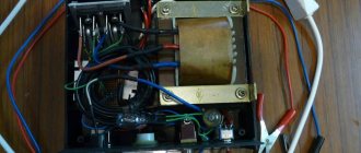
These days, a computer switching power supply (UPS) may be more affordable than a hardware transformer; suddenly he’s just lying around in the trash. UPSs are often converted into laboratory power supplies, but, generally speaking, this is a bad option. The output voltage via the +12 V channel can be raised to a maximum of 16-17 V, which is not enough for design and research purposes. And the level of impulse noise at the output is then, to put it mildly, too high. How to set up an UMZCH with its own noise of -66 dB (which is still very modest), if the power supply is “rushing” at -44 dB or worse? But charging a 60 A/h car battery from a UPS is excellent, and there is no need to install separate protection, everything is already there. They convert the UPS into an auto charger, as a whole, the following. way:
- Remove the output wires except yellow (+12 V), black (common, ground, GND) and the green PC ON logic wire;
- The PC ON wire is short-circuited to ground (connected to any of the black ones);
- Install a mechanical power switch if there is no standard one at the back;
- Using the diagram or guided by your own experience, look for a +12 V resistor in the feedback circuit Rcs in the stabilizer harness;
- Replace it with a 10 kOhm Rn potentiometer;
- By rotating the Rн slider, set the voltage in the +12 V channel to +14.4 V;
- The resulting value of Rн is measured and instead of Rcs, a constant resistor of the nearest value from the standard series is soldered in, the tolerance for variation is up to 2%;
- If possible, a universal voltage and current indicator (see below) is built into the UPS to control the charge; it is powered from the charge circuit or +5 V (red wire);
- Connect the yellow and black wires into separate bundles, securely attach current hoses with clamps for connecting to the battery to them - charging is ready!
No tags for this post.
Functioning algorithm
On most microcircuits that have 6 or 8 pins (sources of receiving and transmitting signals about the state of the battery), two field-effect transistors are installed. One of them is responsible for connecting or disconnecting the load (various elements of the mobile device that consume energy). The second one performs similar actions, but with a current source.
The result of this scheme is as follows:
- When the current reaches its maximum level, the transistor responsible for replenishing the capacity turns off the corresponding device and accumulates energy inside itself, simultaneously releasing it in the form of heat (therefore, when charging the phone for a long time, you can find that it becomes hot), thus protecting the battery from overcharging.
- If the minimum voltage is reached, the transistor responsible for connecting the load turns off all elements, and the mobile equipment is forced into sleep mode. Then, when it is connected to a current source, its operation resumes.
Note! Operation resumes only when a certain current level is reached, so often, when connecting, for example, a discharged telephone to the electrical network, you must wait some time before it turns on. Device operation
Device operation
So, the described circuit elements (both factory-made and those made independently) are required to control the replenishment of capacity and discharge of batteries. This allows you to ensure the safe operation of mobile equipment and increase its service life. In addition, such elements are also needed in renewable energy sources, which also require the management of energy storage and its subsequent transmission to consumers.
History of chargers
The discovery of galvanic electricity led to the creation of the first prototype of rechargeable batteries. In 1798, Italian physicist Alessandro Volta conducted an experiment involving placing copper and zinc plates connected in series in an acid solution. He discovered that when current was passed through the plates after it was interrupted, a residual charge remained on them. Subsequently, Gotero, Marianini, and Becquerel became interested in these experiments. But it was not until 1859 that Plante created the truly first battery.
His experiment was based on strips of lead with a piece of cloth sandwiched between them. He then rolled the strips and immersed them in acidified water. By applying and removing current, he received a potential difference across them, that is, the accumulation of capacitance by the element. Further development led to the fact that when the plates were coated with lead oxides, the formation of the active layer improved.
In 1896, the American company National Carbon Company (NCC) was the first in the world to begin producing batteries. Today it is known as Energizer. Early in 1901, scientist Thomas Edison patented a nickel-cadmium type of battery. At the same time, Waldmar Jungner was developing a nickel-iron type called an alkaline battery. Alkaline batteries are used in transport and power plants. In parallel with the development of batteries, charge recovery technologies are also developing.
Charging Mode
The program controls the voltage and current on the battery. If the voltage is lower than the one specified in the Umax settings, the charging current stabilizer operates with the Is setting. If the voltage reaches Umax, the program stops. Indication charge off.
If the voltage rises above Umax by 0.2, the program stops, ERROR is displayed in the top line. In the bottom line is the voltage at which the shutdown occurred.
If the charge current I exceeds the current Is by 0.2 for a time of more than 5 seconds, the program stops, ERROR is displayed.
If the charging time has expired (parameter H, clock), the program stops, ERROR is displayed in the top line. The bottom line says Time out.
Indication of symbols on the display
- V - measured voltage on battery
- Vs(max) - voltage up to which the charge will be made
- Vmin(m) - minimum voltage on the battery at which the discharge will be turned off
- I - measured charge current
- Is - set charge current
- Id—measured discharge current
- Ii - discharge current set in the menu (discharge current stabilization)
- Imin - minimum current at which the charge will be completed
- H - timer time. For all modes.
- Hi - remaining time before shutdown by timer
- P -capacitance AB-Ah
- LED backlight
1.When the device is connected to the network, display information if the battery is connected
1.1. Voltage to which the charge will be made. Default Vs=14.2 (Selection range in the menu is 1-30 volts.)
1.2.Set charge current. By default Is=0.5A. (selection range in the menu 0.5 -10A. resolution 0.5A.)
1.3. Real voltage on the battery. For example - V=13.7
1.4.Default mode - charging (the mode can be changed in the menu. Names of modes. charge . discharge. kts battery.)
MODE 1.charge
If the battery is not connected, instead of voltage on the battery, display the inscription - no bat. Everything else is the same as when the battery is connected.
Example 1.0. battery not connected
Vs=14.2 Is=0.5A ? Battery Charge
When you press the start button, start the set mode. When pressed again, stop. when the mode is running, the name of the selected mode flashes. When stopped, it lights up constantly.
Example 1.1. battery is connected.
Vs=14.2 Is=0.5AV=13.7 Charge
When the mode is running, instead of the set voltage to which the charge will be made, the real charge current is displayed. Example I = 3.6 A
Example 1.2. charging is in progress.
I=3.6A Is=0.5AV=13.7 charge
After the charging is complete (by a timer or when the set voltage on the battery is reached or the charging current drops to I=min), turn off the charge and remove it - the charge is turned off.
If the charging current exceeds the one set in the menu. And also the voltage on the battery exceeded the one set in the menu - turn off the charge and display the inscription - ERROR.
MODE 2. digit
2. When selecting the discharge mode (when starting this mode, automatically charge the battery to the set voltage and then start discharging.
Example 2.0. Indication in the main mode window. If the mode is not running, the name of the mode (digit) does not blink. When the mode is running, the name of the mode currently used (charge or discharge) flashes.
If the mode is running. AB is not charged. There is an automatic charge, after which the discharge will begin.
I=0.5A charge P=0Ah
2.1 Default discharge current Id = 0.5 A. Selection range in the menu 0.5-10 A. resolution 0.5 A.
2.2. Hi — Time remaining until the end of the discharge, after which the discharge will be disabled by default.
2.3. Measured battery capacity P=????Ah (example P = 45.4Ah). Example 2.1. window during discharge
Id=0.5A Hi=10 P=45.4Ah discharge
After the end of the discharge, give a signal with a pause of 1 second. And so on until another mode is turned on. Apply the signal to pin 4 of the MK. LED out. Display the inscription at the top - P=????Ah. Vm=11.0 at the bottom - OFF digit.
Example 2.2. the discharge is over
P=100.3Ah Vm=11.0 Discharge off
MODE 3. Kts battery. Desulfation.
In the main mode window, if the mode is running, the mode name (KTC) flashes. If it is not running, it does not blink.
3.1. The default charge current is Is = 5A. Range 0.5-10 A
3.2. Discharge current Id = 0.5A. Range 0.5-10 A.
3.3. Voltage on the battery. Frequency 1 Hz.
Example 3.0. desulfation occurs.
I=5.0A Id=0.5A V=14.2 KTTs-AB
After the charging is completed (by a timer or when the set voltage is reached, turn off the mode), display the message - CTC OFF. And the voltage on the battery.
Example 3.1. end of work.
V=14.7 CTC OFF
Discuss the article CAR CHARGER ON CONTROLLER