Variety
The cartridges differ in design depending on their functional and technological purpose.
Lathe chucks are classified according to several criteria:
- Method of attachment to the machine: on the spindle flange, using an adapter flange, directly on the machine spindle.
- Jaw installation: independent movement, mounted directly on the spindle flange.
- Principle of workpiece securing: manual, mechanized (with hydraulic or pneumatic drive).
The principle of manually securing the workpiece
The use of a mechanized drive reduces the amount of auxiliary time required to install and secure the workpiece. The drive ensures precise positioning of the workpiece and centering during installation; this mechanism helps to increase processing accuracy.
Lathe chucks have different numbers of jaws. They can be 2, 3 and 4 cam. The cams are in direct contact with the workpiece during operation and hold it in one position. There are direct and reverse.
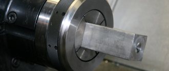
The tree (blank) is fixed by the outer surface or hole for parts in the form of bodies of revolution; prismatic parts are attached to the outer edges.
The cartridge is a complex technological product of a prefabricated design. Various materials are used in the manufacture of assembly units. The body is made of gray cast iron grade SCh 30. The material for the parts is tool steel with high tensile strength and heat treatment. Roughness on working surfaces is not higher than 1.6.
Tools
0 votes
+
Vote for!
—
Vote against!
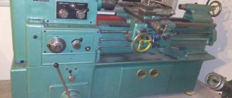
The quality and performance of any equipment depends directly on the condition of its equipment. It is especially important to accurately, quickly and reliably secure workpieces on CNC machines and machines that operate as part of the GPS. To reduce the time required to position the workpiece on the machine, as well as to increase the reliability and accuracy of its fastening, chucks for lathes are widely used.
Features of the lathe chuck
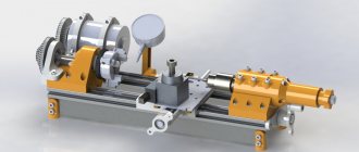
A lathe chuck is an integral part of the equipment complex when carrying out turning operations. This structural part is intended for securing piece workpieces and bar material on screw-cutting lathes, grinders, turret and lathes, as well as metalworking equipment. With a lathe chuck you can clamp workpieces of a wide variety of sizes. The workpieces are attached to the inner plane of its hole, the outer surface or the outer surface for the shaft.
Lathe chucks with mechanized drives make it possible to reduce the auxiliary time required to install a workpiece on equipment and remove it after processing, thereby increasing labor productivity. On the other hand, these products increase processing accuracy, as they ensure coordination of workpieces relative to the working parts of the lathe and their reliable fastening, which eliminates deformation or displacement during processing.
Some of the world's most famous manufacturers of wood lathe chucks in Europe are Rohm (Germany), Bison-bial (Poland), as well as some domestic factories of technical equipment, tools and machine components. These products are quite expensive, but today it is simply impossible to imagine production without the use of lathe chucks.
Operating principle of lathe chuck
The lathe chuck should be used indoors and in the absence of aggressive substances that cause corrosion. Before starting work, the tightening bolts are tightened to the maximum with a wrench, then the lathe chuck is secured on the machine, all bolts are tightened with nuts and the lathe is started. It must be taken into account that low speeds are set to begin with to check the values of the end and radial runout of the lathe chuck at idle speed.
For fastening products on lathes, two- and three-jaw chucks are widely used, less often - four-jaw chucks. To fasten and hold parts, the lathe chuck contains cams, the number of which varies from 2 to 6. In this case, lathe chucks come with independent movement of the cams and with direct attachment of the cams to the flange end of the spindle. Depending on the method of fastening the lathe chuck to the machine, the following types of fastening are distinguished: on the flanged end of the spindle, through the adapter flange, directly on the lathe spindle itself.
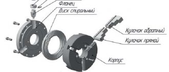
Centering the workpiece in the chucks is achieved by simultaneously moving the clamping jaws in the radial direction. The cams of the lathe chuck move simultaneously with the help of a disk, which has grooves in the form of an Archimedean spiral on one side and a bevel gear, which is associated with three others, on the other. The key sets one wheel in motion, at the same time the disk also turns and moves all the cams evenly. The direction of rotation of the disk will determine whether the jaws approach the center of the chuck (the workpiece is clamped) or move away from it (the workpiece is released).
The clamping force in power chucks is generated by a hydraulic or pneumatic cylinder located at the rear end of the spindle. Through the central hole of the spindle, the cylinder is connected by a rod to the chuck mechanism, which moves the cams that clamp the installed workpiece into the chuck.
During processing, compressed air or liquid enters the rotating cylinder using a special device called a coupling. As a rule, the movement of the cams from a mechanized drive reaches 5-10 millimeters, so the design of the lathe chuck in any case allows you to quickly readjust the product when moving from processing between batches of workpieces.
To increase the accuracy of workpiece fastening when performing finishing machining, it is customary to use overhead non-hardened jaws, which are bored on a machine to fit certain dimensions of the workpiece mounting bases. For this purpose, the main cams clamp a short mandrel to select gaps in all mates, and after that the working surfaces of the overhead cam are bored to the largest diameter of the base surface of the part.
The design of non-hardened jaws and their fastening using a dovetail interface allows the overhead jaws to be installed with an accuracy of 0.02 millimeters and to avoid their subsequent boring. For quick changeover between workpiece sizes, universal non-hardened jaws are required; this is achieved by rotating the round or hexagonal heads of the overhead jaws, which are mounted on the main jaws and bored to the desired diameter, into a certain position. Large-diameter workpieces are fixed in such a chuck with the cam stages placed in reverse.
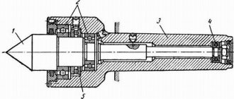
If there is a need to process two similar surfaces, it is customary to use non-hardened cams, the error in fastening the workpieces in which can be reduced to 0.03-0.05 millimeters. Workpieces such as shafts that are longer can be installed in a lathe chuck, which has a rear center pressure.
DIY lathe chuck
You have become acquainted with the structure and main types of lathe chucks, and now we present to your attention a version of a homemade lathe chuck for a wood lathe. The main working part of the cartridge is the elastic sleeve, which has a diameter of 6 millimeters. It is necessary to use two types of bushings - polyurethane and rubber, for which you can take trimmings of sealing harnesses.
The union nut must be made of brass or bronze. Steel can also be used for this purpose, but bronze nuts have less friction. You can make the patch from any material, you can even take duralumin. The body is machined from steel. There must be an internal hole or thread in its shank - this depends on the design of the shaft shank of the device on which the cartridge is to be installed.
The rubber bushing and housing are the most critical parts in the cartridge. Whether the drill clamped in the chuck will “hit” depends on how accurately they are made. To reduce the likelihood of drill “beating,” make both parts in a certain sequence. Machine the chuck body in one setup. This technique will ensure the alignment of the central hole and the bushing shank with a certain accuracy.
The chuck body will remain in the lathe spindle after machining. Insert the elastic sleeve blank inside the cartridge and lightly press it through the patch with the union nut. Insert a drill with a diameter of 1 millimeter into the tailstock of the machine and drill out the clamped bushing. Using this method, it is advisable to make several bushings in stock.
If you are unable to stop the shaft of the drilling device when clamping the drill, you need to make flats for a wrench on the body of a homemade chuck for a lathe so that you can tighten the union nut tightly. In a lathe chuck you can clamp drills that have a diameter of 0.8 to 1.2 millimeters. For drills of a different diameter, the holes in the nut and bushing must be made differently.
The main difference between this chuck lies in the fact that the elastic sleeve will clamp the entire shank of the drill, and in order to install a standard drill in the Verbovoy chuck, it is recommended to cut off its shank. Make the hole for the elastic sleeve not in the nut, but in the chuck body; it should be as close as possible to the clamping device of the machine spindle. This significantly increases the accuracy of drill centering during installation.
Now you know what lathe chucks are for and what function they perform when working on a lathe. In addition, it is not at all difficult to make a lathe chuck with your own hands. To do this, you must first of all decide on the environment in which the product will be used and strictly follow our instructions.
Do-it-yourself wood lathe with a copier
A copier is a device that allows you to make carvings on a workpiece according to a given template. Thanks to it, it becomes possible to produce similar parts at high speed. A wood copying machine allows you to avoid painstaking work and is most often used in home workshops.
To make a copy element yourself, you can use a manual router as a basis. It must be placed on a plywood board, the thickness of which should not be more than 1.2 cm. The standard dimensions for such a workpiece are 20x50 cm.
A lathe and copying machine allows you to make monotonous wooden parts with your own hands
Then you need to drill holes for the fastening elements, as well as install small bars that will serve as supports for the functional part. Next, the cutter must be placed between the clamps and secured using ordinary self-tapping screws. After this, all that remains is to place the block (7x3 cm) on the machine. It is used to attach the stencil.
This is how you make your own wood lathe with a copier. Videos that allow you to clearly understand this issue can be viewed on the Internet. Making this device is not that difficult. All work comes down to a simple modernization of a conventional unit.
Making a lathe chuck for wood with your own hands
The manufacture of jaw chucks requires high-precision industrial equipment and it is hardly possible to make them in a home workshop. However, there are simpler designs that are not difficult to build with your own hands.
Homemade wood turning faceplate with adjustable clamps
You will need a flat sheet of steel with a thickness of at least 10 mm, a steel angle 50x50 mm, eight M8x30 bolts with nuts and washers. You should think in advance about how the device will be mounted on the machine and, if necessary, make or purchase an appropriate threaded bushing. After this you can proceed:
- Mark on the existing plate a circle of the required diameter and two axes passing through the center and intersecting at right angles.
- Cut out the faceplate blank using a jigsaw according to the markings and sand it thoroughly.
- Cut through grooves along the resulting axes, stepping back a few centimeters from the center and not reaching 2 - 3 cm to the edges. This can be done easier by pre-drilling holes slightly larger in diameter than the stocked bolts.
- Saw off four identical sections from the corner and drill one of the shelves of each with the same drill.
- In the second shelf of the corners, cut an M8 thread and screw in the bolts.
- Weld or solder a threaded bushing for mounting on the shaft.
- Screw the corners to the faceplate with bolts through washers.
- Attach the resulting wood chuck to the lathe.
To fix it with such a homemade cartridge, the corners are moved to the desired position and secured by tightening the nuts; the part is finally tightened with bolts screwed into the threaded shelves.
AlfFisher. My work: Homemade lathe chuck.
Today I watched the video of my colleague Kirill https://www.youtube.com/watch?v=f6-aA3AwTm8 and decided to write this post. I had to solve the issue of a homemade chuck for a wood lathe a long time ago, when my machine did not yet have a 3-jaw chuck.
Since I designed the cartridge based on modest capabilities, I tried to make the design as simple as possible.
=
There are 2 homemade metal clamps (3) installed on the disk.
To make work safer, an additional guard 1, glued together from several layers of plywood, is installed on the faceplate (2).
| Rice. 1 Chuck device. |
To access the clamping bolts, 2 windows (4) are cut out in the safety guard, allowing the use of a socket wrench. I made the clamps in the form of separate elements, but during installation, to reduce the dimensions of the cartridge, I welded them together (at several points). This made it possible to use only 4 bolts for fastening to the disk.
| Rice. 2 Clamps and center. |
The clamps are attached to the faceplate with M6 bolts, which are screwed in from the reverse side and cut behind the face with the plane of the clamps. To prevent the bolts from unscrewing due to vibration, the ends of the threads are cored. After attaching the clamps, the disc is screwed to the flange.
| Rice. 3 Clamping device. |
The base of the clamp (2) is made from a 60 x 60 angle. One shelf is shortened and an M10 thread is cut into it. In the second shelf, 2 mounting holes (3) are drilled and an M6 thread is cut. To reduce the backlash of the clamping bolt in the hole, an additional nut (4) is welded to the base.
The clamping jaw is welded from an angle (7) with a section of 35 x 35 and a metal bar with two holes (5). One hole includes a clamping bolt (1), machined to Ф 6 mm. A groove 4 mm wide is made on the machined part.
A locking pin (6) is pressed into the second hole, preventing the jaw from slipping off into the clamping bolt.
The longitudinal stroke of each jaw is approximately 35 mm, which allows you to clamp a square with a cross-section from 30 to 65 mm, and when using additional spacers, you can clamp bars of a smaller cross-section.
To prevent parts from slipping out of the jaws, No. 40 sandpaper is glued to the inner surface.
A little later I will try to make a video about my cartridge design.
And that’s all for today.
Like, write comments, ask questions and share on social networks :).
alfisher.blogspot.com
What other types of machines can be made
Even the simplest homemade wood lathes can be turned into multifunctional devices by equipping them with additional equipment. In addition, using ready-made components and parts from other equipment, you can assemble an excellent model for home creativity.
With a copier
This device will make it possible to put into production the production of similar parts. With a copier, the easiest way to turn out a chess set, cutlery handles and other items. The essence of this device is to fix a template with the profile of a future plywood blank or a finished wood part on a tool rest. To work in this case, you will need to upgrade the hand cutter by installing a limiter on it. When processing wood, the cutter processes the part, and having reached the required diameter, it rests against the edge of the template, and then, moving along the relief, it creates the desired profile on the part itself.
Mini
A mini wood lathe is needed primarily to gain initial woodworking skills. The tabletop machine is also useful for creating crafts, such as checkers or chess, and for professional use - for modelers creating architectural models or exhibition dioramas. This model is usually small in size, because most parts are rarely longer than 10 centimeters.
From an electric drill
This type of tool is simply created to be used in the construction of lathes for woodworking. Essentially, this is a ready-made headstock - there is a motor, there is a clamping chuck, there is an electric drill speed control. All that remains is to clamp the body in a clamp and install the tailstock opposite. Of course, it’s not worth working on it for hours, but for small parts this is what you need.
Main material
The next question is what to make a homemade lathe from? The answer seems obvious: made of metal, after all, the machine cannot be weaker than the workpiece? How did the primitives drill into stone with wood? How did the ancient Egyptians use wood and copper (there was no bronze yet) to build pyramids? And see above about the main issue of machine tool building.
A lathe for processing wood can be made of metal (pos. 1 in the figure), metal-wood, pos. 2, from scrap materials with minimal use of metal, pos. 3 and even... without a frame, pos. 4. So, on any of them, a sufficiently experienced and careful craftsman can regularly work for a long time with maximum precision for wood. Wood is not only a noble, but also a grateful material.
Homemade wood lathes from various materials
What tree?
Yes, but what kind of wood should I take? The best is oak without defects, seasoned, having undergone complete natural shrinkage and shrinkage. Lathes made of high-quality oak 100 or more years ago are still in operation. As for homemade work, the bed and headstocks of an oak (literally) machine are made very simply, see below.
If there is no oak lumber of suitable quality, then you can get by with ordinary construction pine, but the frame will have to be made according to a frame-beam power structure. In Anglo-Saxon countries, where oaks have long been registered individually, such home lathes are very common. Drawings of an “English” wood lathe with a frame made of ordinary timber are shown in Fig; dimensions in inches. This is actually an ancient foot-operated machine with a crank, adapted for an electric drive. To return it to a non-volatile form, it is enough to extend the middle stand of the frame to the bottom, place it on a paw and mount the pedal with a connecting rod, crank and flywheel, see above.
Drawings of a wood lathe with a frame made of ordinary construction lumber
A simple way to make your own frame
The reliability of the bed is a key characteristic of the machine. Human safety and the quality of the product depend on the properties of the material and the quality of the connection of the parts of the frame.
Based on these requirements, the choice falls on metal profiles, chipboard, plywood or solid wood (preferably solid wood: oak, birch or the most common: pine).
If the choice is on a metal frame, then you need to choose a channel, an I-beam or a profile pipe that will carry the load-bearing functions of the machine. Here the choice depends solely on the availability of the material, its price and ease of installation. However, the metal frame is the simplest in design: you only need two I-beams, on which the engine, tailstock, tool rest and caliper are then mounted.
If the choice is wood or chipboard, then based on a preliminary sketch-drawing with the existing dimensions of the engine and all other elements, the design of the frame is formed. As a rule, it consists of a table top, which acts as a base, a stand for the tailstock and a box on which the motor and headstock axle are mounted.
In addition, two parallel slats are run between the headstock racks, on which a movable support board is attached. A gap of 5 cm is maintained between the slats. Afterwards, it is necessary to weld the frame with a welding machine - this will give additional strength to the structure.
If the machine is supposed to be a tabletop machine, then there is no need for legs, but when processing heavy and massive elements, the bed should be independent and its stability should not raise questions. In this case, it is necessary to provide legs. They are made from rolled steel, for example, angle or timber.
The dimensions of the machine primarily depend on the goals pursued by the master. Most operations at home are performed with products up to 80 cm in length, so most often the length dimensions of the machine are 80 cm. If the frame is made of metal, then two blanks of equal length are cut with a grinder.
Manufacturing Features
Homemade wood lathes are made quite easily and simply if you know in principle what a lathe is and what it consists of. A small unit with dimensions of about 80x40 centimeters in length and width with a height of 35 centimeters does not take up much space, but allows you to process workpieces with a diameter of up to 25 centimeters and a length of 20-40 centimeters.
A lathe provides unlimited possibilities in the manufacture of dishes, furniture, and decorative elements.
Thanks to it, you can make any product in the form of bodies of rotation for your own use or during construction and other work.
Capabilities and technical characteristics of woodworking turning equipment
When constructing a wood lathe with your own hands, the design of the unit can be quite simple. However, in order for the unit to efficiently perform the functions assigned to it, before constructing a wood lathe with your own hands, you should study the specifics of the equipment and the features of its use.
When constructing a wood lathe with your own hands, the design of the unit can be quite simple
To use the unit to perform a minimum list of technological operations for wood processing, the machine must include the following structural elements in its design:
- frame;
- headstock;
- tailstock;
- electric drive;
- a unit for regulating the rotation speed;
- special fasteners.
In addition, in order to carry out precise processing of wood, the machine design must have a special stop for cutting tools of different shapes.
If it is necessary to perform complex operations, the design of the machine must provide for the possibility of displacing the workpiece being processed relative to the center of the rotation axis.
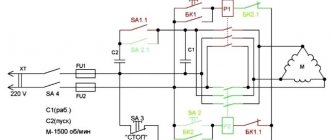
The main structural element of a woodworking lathe is an electric drive. Most often, a three-phase electric motor is used as the latter. For this reason, care should be taken to ensure that a three-phase power supply line is connected to the workshop. The rotational speed of the electric motor used in the design of the unit should be no more than 1500 rpm. Depending on the type of electric motor, its connection to the network is carried out as a “star” or “triangle”.
The main structural element of a woodworking lathe is an electric drive
The most common dimensions of a DIY wood lathe are the following parameters:
- length – 800 mm;
- width – 400 mm;
- height – 350 mm.
These dimensions of the unit make it possible to process workpieces that have a diameter of up to 250 mm and a length of up to 200 mm without the use of centering using a tailstock. The workpiece is secured on a special plate. When using a tailstock for centering, the length of the workpiece can be increased to 400 mm.
What other types of machines can be made?
Before creating your own lathe, you should study those varieties that were invented by many interested people. Among the machines, both home-made and factory-made, the following types are distinguished.
Turning and milling
Such a machine is already a powerful modification of previous versions of machines. Most often, a turning and milling machine is equipped with a CNC, because it is extremely difficult to manually control the milling machine with high precision. However, such a machine has a right to exist and is widely used for domestic needs. Its design consists of:
- Beds.
- Electric motor for rotating the headstock.
- A manual milling cutter placed on guides that ensure its movement along the axis of rotation of the workpiece.
With a copier
A lathe and copying machine is necessary when creating a large number of identical products; most often you hear about dishes and balusters for stairs.
There are several options for making a copy lathe: with a router, with a circular saw and with a chisel. All these methods involve the use of patterns. A pattern is a profile of a future product, which is cut from thin plywood.
A handrail is attached along the lathe along the entire length of the workpiece. The pattern is mounted behind the lathe. A cutter or cutter is attached to the handrail, the movements of which are regulated thanks to a stop running from the cutter, cutter or saw to the pattern.
Thus, during the rotation of the block, the cutting tool completely repeats the silhouette of the plywood profile with sufficient accuracy.
Mini
For many household needs, it is not necessary to create a unit of impressive size, capable of rotating a log with a radius of 300 mm. Sometimes a machine with an extremely simple design is sufficient, in which the engine can be a drive from an old tape recorder, powered through a power supply. For the bed of such a machine, you can use a board 150 * 20 and long, which depends only on the needs of the craftsman.
For such a mini-machine, a belt drive would be superfluous, so most often the headstock is mounted directly on the motor shaft. And the head from a drill or a homemade chuck with three clamping screws serves as a faceplate.
The tailstock is made of a block, in the center of which a hole for the shaft is drilled exactly at the height of the motor axis, which can be a dowel-nail. If you provide the machine with a power supply with adjustable output voltage, you can get the unit with a speed controller.
From an electric drill
An electric drill can be found in almost every home. The advantage of a machine driven by an electric drill is that there is no need to buy a separate motor. Drill-powered designs range from the most basic, where the drill is clamped to the table.
On the contrary, the tailstock is mounted using a pair of angles and a nail or a sharpened screw, to a more advanced one, in which the drill serves as a source of rotating force, but is not directly involved in the process of rotating the workpiece. The second method protects the motor from overheating and stalling under overload.
In the video you can see how to make a wood lathe with your own hands from a drill.
From a washing machine motor
It is a standard layout of a lathe with a motor, direct or belt drive, bed and two headstocks.
When constructing a lathe from a washing machine motor, it is necessary to remember that the motor of a household appliance is designed to circulate with an unbalanced load, but this does not mean that the tailstock can be abandoned. Its presence is mandatory especially when working with long and heavy workpieces. The design of such a lathe is easy to implement at home. To do this you need:
Weld or bolt two steel pipes and attach a motor from a household appliance to one end. Fix a block between the pipes with the ability to move it along the frame; the corner of the tool rest will be attached to it. On the opposite side, the tailstock is installed in accordance with the instructions outlined above.
Money loves the bill
There are several reasons, the first is economic. The store may not have the ammunition you need for sale. Since the early 2000s, our arms market has presented a quite encouraging picture: almost everything from legal long-barreled weapons could be purchased. European and American manufacturers have become a strong presence in hunting stores, displacing domestic shotguns and rifles. This was especially felt in the segment of hunting rifled weapons with manual reloading: at that time, Russian factories offered only Los, Bars carbines and the Old Testament Mosin rifles. At the same time, Remington and Mossberg products, already equipped with optical sights, were cheaper than the stock “Moose”.
Back in 2013, an American Mossberg 100ATR with a Bushnell sight already installed cost 25-29,000 rubles in a store. Domestic “Moose” is 4-5 thousand more expensive.
Along with imported rifles, new cartridges also came to the Russian Federation. Greater power, accuracy, flatness and workmanship distinguished them favorably from the usual line of ammunition. But since September 2014, the same United States has not issued or renewed a single license for “arms” trade with Russia. As a result, the people, who were cheerfully buying weapons of exotic calibers, began to think: what to do with this property now?
An example from life: at one time I came across an American Marlin carbine inexpensively. I have long wanted something powerful enough for driven hunts for elk and wild boar, and the lever action manual reloading played its role (like in a movie about cowboys!) - in general, I took it.
.444 Marlin Carbine
Now imagine: there is only one option on the market for the required caliber cartridge - .444 Marlin, and it costs 350 rubles apiece (and don’t forget about the shipping costs and waiting time).
.444 Marlin cartridge
To shoot a gun well, you need to do it a lot and often. During Saiga training, I burn one and a half hundred rounds of 5.56x45 mm cartridges, which cost 9.5 rubles. The same amount of .444 ammunition will cost 52,500 rubles. On the economic side, everything is clear.
The second reason is the opportunity to make “your own cartridge”, ideal for your weapon and conditions. The rifling pitch of the barrel, the degree of wear, the weight and shape of the bullet are many factors that ensure an accurate shot. A well-assembled cartridge, weighed on all sides and measured, will give better results than a gross, factory-made one.
Sunday, March 12, 2022
How to make a chuck for a wood lathe
Today I will continue the topic of a homemade lathe and accessories for it.
I haven't made a video on this topic for a long time. And now, while the video is still being prepared, I decided to write this article.
I already raised the topic of the chuck in this article: Homemade lathe chuck.
There are 2 wood lathes in use in my workshop and another one in the making.
I talked about the big machine in one of the old videos:
— — And I already spoke in detail about the second (desktop) in this video: — —
I made quite a lot of equipment for both machines. These include faceplates, various types of tridents and drive couplings,
How to do it yourself?
Think in advance about how the product will be secured to the machine, and, if necessary, make or buy a threaded bushing. After that you can continue.
- On the existing plate, mark a circle and two axes passing through its center and intersecting at an angle of 90 degrees.
- Use a jigsaw to cut out the front panel according to the mark and sand it well.
- Grooves are cut along the resulting axis a few centimeters from the center and two to three centimeters from the edge.
- Saw the corner into four equal parts, and drill a hole in each side with a drill of the same size.
- Cut an M8 thread in the second corner strip and screw in the bolt.
- Install the threaded bushing for mounting on the shaft.
- Secure the bracket to the front panel using bolts and washers.
- The last step is to install the chuck on the lathe.
To secure the workpiece in this homemade chuck, the angle is moved and fixed by tightening the nut, and finally, the workpiece is clamped with a screw screwed into the thread.
Jaw chucks
The most convenient and functional. They work both in compression and expansion, so they can grip the workpiece both from the outside and from the inside. They differ in the number of jaws and their drive mechanism. Unlike metalworking, two- and three-jaw chucks are practically not used for turning wood. Options with a spiral drive and non-removable jaws are also not popular. The most common type of lathe chucks for woodworking are self-centering four-jaw, with a rack-and-pinion transmission mechanism and replaceable jaws. They are supplied to the Russian market by the brands Axminster, Jet, Barracuda and others, less well-known companies.
Types of cams
According to their shape and purpose, replacement jaws for wood lathe chucks are divided into several types, which have special markings:
- A, G, M – for compression, differ in size and depth of grip;
- D and F – act on unclenching;
- C and H are universal. Different shapes of sponges;
- To work with soft, compression-sensitive wood, cams with rubber fastenings are used.
So what now?
Let's return to our native aspens. Today, none other than Vladislav Reznik, an authoritative man, a passionate hunter - and, for a moment, a multimillionaire - has taken on the task of pushing through amendments to Russian legislation. This time, a positive response to the initiative was received from the government of the Russian Federation, signed by the deputy chairman of this body, S. Prikhodko, albeit with a reservation:
“The provided opportunity to independently equip cartridges for sporting firearms with a smoothbore gun and firearms with a rifled barrel affects tens of thousands of commercial hunters, athletes, and residents of indigenous peoples who extract biological resources for food.”
“The implementation of the bill will significantly solve problems, including those related to the implementation of professional activities, and will reduce the financial costs of these categories of citizens.”
“In order to ensure control over the quality of self-loading of cartridges for rifled weapons, the bill should include rules aimed at the need to educate citizens on the rules for safely loading cartridges for firearms with a rifled barrel.”
The gentlemen of the deputies attacked the sick - the fate of the indigenous small peoples. Where to go?
And... accepted on November 15, 2022.
DIY vacuum chuck for wood
If your lathe's headstock spindle has a through hole for knocking out the gear center, you can add a homemade vacuum chuck to your arsenal. For this you will need:
- Powerful vacuum cleaner
- Closed bearing, approximately equal in outer diameter to a vacuum cleaner hose
- A piece of thick rubber hose for connecting the vacuum cleaner and the bearing
- Clamp
- Standard faceplate with hole in the center
- A small piece of MDF or thick plywood
- Textolite for adapter
A bushing is machined from the textolite, one side of which should be equal in diameter to the internal size of the bearing, the other - to the spindle. This homemade adapter is pressed into the bearing using glue; it will be held in the machine due to the tightness of the fit. The resulting structure is connected with a piece of hose to the vacuum cleaner and secured with a clamp.
A disk is cut out of MDF or plywood, attached to a faceplate and ground. It is better to make the surface slightly concave. To ensure a tight fit, linoleum or thin rubber is glued on top. The disk is drilled through the center to remove air. A similar self-made chuck provides a pressing force of 40 - 50 kg, sufficient to hold medium-sized parts during finishing.
If you find an error, please select a piece of text and press Ctrl+Enter.
Tips for use
Proper use of a lathe involves the following.
- Regular cleaning of equipment and regular chip removal will help minimize downtime, breakdowns and waste in turning operations. If maintenance is not carried out systematically, equipment breakdowns may increase dramatically, durability may decrease, and production costs may increase.
- To avoid equipment failure, you should regularly check the condition of the cutting edges and backs of working tools, sharpen or replace dull tools in a timely manner.
- All necessary components such as oil, coolant, tools, lathe accessories and fasteners must be of the correct quality and grade.
- Replacement of faulty parts and tools, elimination of simple faults.
Selecting a transfer method
In most homemade wood lathes, the working drive is provided by the two most popular methods - direct transmission or through belts. Both schemes are excellent for small-sized lathes with primitive devices for clamping a wooden workpiece in the form of a trident and a cone.
Direct transmission
This is a simple and effective way to drive a turning shaft. The actual working shaft here is the rotor shaft of the electric motor. The engine itself is attached to the frame or raised above the support. A clamping device is installed on the axle - a lathe chuck, a faceplate or a regular trident. This is, in principle, the whole scheme of direct drive of a lathe. The advantage of this scheme is that there is no need to look for a special turning shaft, grind out supports for it and center it. In the motor housing, the shaft is already mounted on bearings, and the engine itself has standard mounting units. The disadvantage of this scheme is that it is necessary to protect the windings from dust and shavings that will form during wood processing, and also, if you clamp the workpiece too tightly, there is a risk of the motor jamming and failure.
In addition, direct transmission does not allow adjustment of the speed. If the engine produces 1425 rpm, then the workpiece will also rotate, alas, this is clearly not enough for turning hardwood.
Belting
The design of the headstock using a belt drive significantly expands the capabilities of the lathe. Even if a pulley of the same diameter is used, this makes it possible to increase the shaft rotation speed and protect the electric motor from heavy loads; in this case, it is definitely not in danger of jamming.
If a multi-lane pulley is mounted on the working shaft, and the engine is mounted on a movable slide, then it becomes possible to regulate the speed of rotation of the shaft by moving the belt from a smaller diameter to a larger one. This is the best option; it makes it possible to process wood of a wide variety of species.
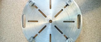
Types of faceplates
The simplicity of the faceplate design and wide range of use have given rise to a large number of ways to secure workpieces. However, the device is not completely universal. Different situations may require several different modifications.
Faceplate with T-slots
On the surface of such equipment there are T-shaped grooves, similar to those used on tables of milling machines. Special stops or fastening nuts are inserted into these grooves. The workpiece is pressed to the plane using screws. The design of the device allows you to fasten almost any product. The arrangement of grooves on the surface of the disk is usually orthogonal. Depending on the purpose, the number and frequency of grooves may vary.
Faceplate with through grooves
This type is distinguished by the presence of grooves milled through the part. The workpiece is secured by installing screw clamps. In some cases, the part is simply screwed on from the reverse side. Grooves are most often located along a radius. There are also modifications with ring-type through grooves.
In most cases, grooved faceplates are used for metal lathes. Other turning devices can be easily installed on their surface.
Faceplate with holes
The working surface of the disk of this device has a number of holes located according to the dimensions of the workpiece being fixed. The central hole is threaded, necessary for direct fastening to the spindle shaft. The presence of threads in the mounting holes allows for fastening with standard screws. In other situations, the clamp is performed similarly to the previous option. When using a similar faceplate for a wood lathe, the future part is secured through the holes with ordinary self-tapping screws.
Drive faceplates
When installing a workpiece between two centers, it is necessary to ensure the transmission of torque from the spindle shaft to the workpiece. For this purpose, leash tools are used. Structurally, they are a disk with a slot or hub on the edge. A clamp is put on the part, interacting with the hub, and thereby ensuring rotation of the product.
Faceplates with squares
When processing products with low rigidity, modifications with squares have been used. The workpiece in such devices is mounted on a separate flat or prismatic base. The base itself is made in the form of an angle, the second edge of which is attached to the surface of the washer. In order to maintain the integrity of the workpiece, its fastening is provided at several points over a large area.
Universal and special faceplates
Universal options are suitable for performing a large number of operations and are a combination of several previous modifications. They are based on a base washer, to which replaceable devices are attached - squares, cams, centers and other elements.
Despite its versatility, standard equipment is not always able to provide reliable fastening of unique parts of complex shapes. In this case, the design and manufacture of special machine tools is carried out. The faceplate drawing can be very complex. Another version of special devices, on the contrary, is involved in mass production. To fasten a part of the same type, there is no point in using universal machine tooling. A device designed for a specific task is quite sufficient. To increase overall performance, such a faceplate can be equipped with additional fastening and centering devices.
Making fixtures
Usually the faceplate is included in the standard set of machine accessories. In case of its absence, as well as to perform specific work, non-standard equipment is manufactured. Structurally, it is characterized by low complexity and is accessible to developers with a low level of training. In the simplest case, a homemade faceplate for a lathe chuck is made using only a drilling machine. A flat plate of the required thickness is suitable as a workpiece. The use of milling and turning equipment will significantly complicate the final design and bring it closer to factory models.
If you find an error, please select a piece of text and press Ctrl+Enter.
Types of universal devices
Modern manufacturers offer users an extensive range of lathes. Among the most popular, the following types can be distinguished: turning-screw-cutting, turning-milling, turning-carousel, turning-turret.
Screw cutting machine
A special feature of this type of equipment is the presence of a tailstock quill stroke. Thanks to this, it is possible to equip it with a drilling chuck. This allows the machine to be used not only for turning operations, but also for turning workpieces with different profiles, leveling, making grooves and recesses in workpieces, cutting sizes to the required specifications, and drilling holes. For this, dies, cutters or taps can be used.
If the choice fell on a screw lathe, it is recommended to take into account the following properties:
- The size (diameter) of the workpiece, which can be calculated by measuring the distance from the bed to the axis of the device.
- Maximum part length. This figure in most models does not exceed 2033 mm.
- Machine weight. With increasing weight, the level of rigidity of the device increases, which has a direct impact on the accuracy of the operation performed. You can purchase units whose weight ranges from 600 to 4250 kg. Such machines are very popular both in enterprises and in home workshops.
Milling device
Using this type of equipment, you can turn workpieces not only from ferrous and non-ferrous metals, but also from plastic and wood. The design of the device combines two types of machines (milling and turning).
A universal turning and milling machine can be used to perform such types of operations as continuous turning, thread cutting, chamfering, fillet cutting, cutting straight and curved grooves, and drilling holes. This became possible due to the presence of a milling part located in the vertical plane of the frame. Such machines are often installed in school workshops.
The popularity of turning and milling equipment is due to the presence of its inherent advantages:
- Availability. The combination of two types of machines leads to cost savings.
- Compact size. It can be installed in a workshop with a small area.
- Possibility of mounting a variety of additional elements (cutter, drill, tap, reamer, cutter, chisel).
When choosing this type of equipment, it is necessary to take into account the following characteristics:
- distance between centers;
- workpiece size;
- diameter of crosscut and end mills.
The presence of these qualities determines the popularity of turning and milling equipment among users.
Carousel machine
Machines of this type are mainly used for processing large diameters (more than 2000 mm) and sizes in large enterprises.
Revolving unit
The main purpose of this type of device is to process workpieces made from calibrated rods. The peculiarity of the machines is that the cutting mechanism is mounted on a rotating drum.
https://youtube.com/watch?v=QkSWxDsgXVw
Machine tools with numerical software
When working with this type of machine, minimal operator participation is required. It is also worth noting the ability to perform all types of operations with high precision.
Each of the above types of metal lathes has design features and purpose.
How to choose a part
The optimal chuck model for the machine is selected based on a comprehensive methodology. First of all, the technical data of the machine and the operations performed are taken into account. Based on this, the following parameters are analyzed.
Design - the method of securing the workpiece, the location and number of cams are important.
Parameters of the workpiece - you need to know the maximum and minimum diameter of the shaft and hole of the future workpiece, weight, length, configuration. These factors influence the method of fastening - direct or reverse cams.
The size of the hole in the hollow spindle for installing a rod workpiece. As well as the rotation speed range.
The operating conditions of the lathe chuck require placement in a closed room, where the negative impact of natural factors and aggressive environments that can cause corrosion is excluded.
The lathe chuck is an integral part of the lathe and without it machining is impossible.
Making a lathe chuck for wood with your own hands
The manufacture of jaw chucks requires high-precision industrial equipment and it is hardly possible to make them in a home workshop. However, there are simpler designs that are not difficult to build with your own hands.
Homemade wood turning faceplate with adjustable clamps
You will need a flat sheet of steel with a thickness of at least 10 mm, a steel angle 50x50 mm, eight M8x30 bolts with nuts and washers. You should think in advance about how the device will be mounted on the machine and, if necessary, make or purchase an appropriate threaded bushing. After this you can proceed:
- Mark on the existing plate a circle of the required diameter and two axes passing through the center and intersecting at right angles.
- Cut out the faceplate blank using a jigsaw according to the markings and sand it thoroughly.
- Cut through grooves along the resulting axes, stepping back a few centimeters from the center and not reaching 2 - 3 cm to the edges. This can be done easier by pre-drilling holes slightly larger in diameter than the stocked bolts.
- Saw off four identical sections from the corner and drill one of the shelves of each with the same drill.
- In the second shelf of the corners, cut an M8 thread and screw in the bolts.
- Weld or solder a threaded bushing for mounting on the shaft.
- Screw the corners to the faceplate with bolts through washers.
- Attach the resulting wood chuck to the lathe.
To fix it with such a homemade cartridge, the corners are moved to the desired position and secured by tightening the nuts; the part is finally tightened with bolts screwed into the threaded shelves.
How to make a device yourself?
At home, it is possible to make the simplest cartridges, since high-precision parts obtained in industrial production may not be possible. It will not be difficult for a real craftsman to produce a cartridge for both a woodworking machine and a metalworking machine.
On wood
Algorithm for making a chuck for a wood cutting machine:
- grind the body of the future cartridge on a machine;
- then leave the body in the lathe spindle;
- insert the workpiece from the elastic sleeve and secure it with a union nut through the patch;
- Insert a drill with a diameter of 1 mm into the thrust head of the equipment and drill out the clamped bushing.
This way you can make a few bushings in reserve.
Homemade metal cartridge
The chuck of a metal cutting machine is subject to not only transverse but also longitudinal loads. The cartridge is made of a metal pipe and is secured with 4 bolts. These bolts go into welded nuts.
The most common are three-jaw chucks. This is a massive faceplate with radial grooves.