A shaft is a machine part that transmits rotating forces. A shaft is a rotating body of cylindrical, conical or other shape, supported by two or more supports. Pulleys, gears, flanges, flywheels, etc. can be attached to the shaft.
Typical shaft manufacturing technology:
- Cleaning;
- Heat treatment;
- Editing;
- Procurement operation (cutting);
- Centering;
- Turning operation;
- Milling operation;
- Drilling operation;
- Heat treatment;
- Editing;
- Grinding operation;
- Locksmith operation;
- Package.
Types of blanks for shafts in individual production:
- round rolled products;
- forgings;
- stamping;
- welded billet from pipes and round bars;
- square rental.
General information
The following grades of steel are used for the manufacture of shafts: 25, 30, 35, 40, 45; 45G2, 40Х, 35ХС, 40ХС, 35СГ, 30ХН3, 35ХН3М, 45ХН2МФ, etc. Steels 45 and 40Х are most often used. For large shafts and spindles, cast shafts made of high-strength cast iron grade VCh 45-5 (GOST 7293–79) are used. The main requirements for workpieces for shafts are good straightness and the smallest processing allowance. The deviation from the straightness of the workpiece axis should not be more than 0.1...0.15 mm per 1000 mm of length. When straightening on special straightening machines, deviation from straightness can be achieved up to 0.05 mm per 1000 mm. Typical machine setup:
- Chuck - length up to 5 shaft diameters;
- Chuck with center - length from 5 to 12 shaft diameters;
- Chuck with center and rest - length above 12 shaft diameters.
- editing;
- centerless peeling (not performed for calibrated bars);
- cutting into dimensional pieces;
- facing and making center holes (during further processing on a turret machine or automatic machine, the rod is not centered).
Pre-processing of forged, stamped and welded workpieces involves cleaning them (removing scale, burrs, burns, cleaning welds (if necessary)), roughing or milling, making center holes (if machining will be carried out in the centers of a lathe). At the stage of pre-processing of rolled products, straightening, peeling, cutting and making center holes are carried out. Procurement operations for rods are usually performed in the following order:
Center designs
Turning centers can have different designs. The most common one is a cone, a workpiece is put on it, as well as a conical shank. The shank must match the holes of the quill and spindle of the machine.
To secure workpieces with external cones, reverse centers are used. The tapered end should coincide with the middle of the shank. To check the coincidence, the center is inserted into the spindle and started at low speeds. The serviceability of the part is indicated by the absence of runout.
The rear center is most often stationary, the front center rotates with the workpiece and spindle. As a result of friction, both surfaces fail, so it is necessary to apply lubricant:
- chalk - 25%;
- grease - 65%;
- graphite - 5%;
- sulfur - 5%.
Before mixing, it is necessary to grind the sulfur and chalk into powder without lumps. If lubricant is not used, the surfaces of the centers will collapse and their configuration will change.
When turning workpieces at high speeds, the centers wear out faster, and the hole in the end of the part itself increases. To reduce the destruction of the rear cone, a wear-resistant layer is fused onto it.
The standard center is used at speeds up to 120 rpm. When working with bulky and heavy workpieces at high speeds, when removing large chips, the structure has little rigidity: the part begins to vibrate and can be pressed out.
rotating center
Therefore, they use rotating centers mounted in the rear rack. It contains a spindle that rotates in an angular contact bearing. For high loads, a roller bearing is preferable; for medium loads, a ball bearing is preferable.
Heat treatment
To reduce internal residual stresses in workpieces, refine grains and improve machinability with blade tools, forgings and stampings made of high-carbon steels (C > 0.5%) are subjected to heat treatment (annealing or normalization). Annealing is carried out by slowly heating the workpiece over its entire cross-section to temperatures 30–50 °C above the critical point temperature Ac3, holding at this temperature, and then slowly cooling the workpiece together with the furnace. Normalization is carried out by slowly heating the workpiece over the entire cross-section to temperatures 30–50 °C above the critical point Ac3, holding at this temperature and subsequent cooling in air.
Edit
Most workpieces (especially large and non-rigid ones) have shape errors (curvature).
To eliminate curvature, straightening is used (by bending, stretching, heating, etc.). Straightening is an operation to eliminate shape errors (curvature) of workpieces in hot or cold states, carried out manually or using special equipment. Manual straightening of rods and blanks for shafts is straightened in a cold state on manual presses (prisms). Manual editing accuracy can be achieved within 0.05...0.1 mm. Manual straightening is a low-productivity operation, and it is used for small batches of parts, that is, in individual and small-scale production. Mostly, enterprises use machine straightening, carried out on hammers, leveling machines and eccentric leveling presses, as well as on hydraulic presses using special devices. In some cases, workpieces are straightened not only before machining, but also during processing, when, when removing the outer layers of metal, internal residual stresses arise, causing the axis of the workpiece to bend or warp. Blanks in the form of forgings and stampings with significant diameters and lengths are straightened in a heated state under hammers and on eccentric, hydraulic, pneumatic, and friction presses. Before straightening the shafts, the places to be straightened are determined, and the shafts are straightened by placing them on prisms. Table 1—High-quality hot-rolled round steel. GOST 2590-2006. Tolerances for curvilinearity.
| Nominal diameter of rolled products, mm | Curvature, % of length, no more, for classes | |||
| I | II | III | IV | |
| Up to 25 incl. | 0,2 | 0,5 | Not regulated | Not regulated |
| Over 25 to 80 incl. | 0,4 | 0,45 | 0,5 | |
| Over 80 to 200 incl. | 0,25 | |||
Curvilinearity calculator.
Rod length, mm
Curvature tolerance, %
Allowable curvature, mm
Editing is also necessary due to the curvature of the rolled product.
The curvature of the rolled product is measured over a section of at least 1 m in length at a distance of at least 100 mm from the end of the bar. Table 2 - Calibrated round steel. GOST 7417-75. Tolerances for curvilinearity.
| Nominal diameter of rolled products, mm | Limit curvature depending on the tolerance range | |||||
| per 1 meter of length, mm | full length, % | |||||
| h9 | h10 and h11 | h12 | h9 | h10 and h11 | h12 | |
| Up to 25 incl. | 1 | 2 | 3 | 0,1 | 0,2 | 0,3 |
| Over 25 to 50 incl. | 0,75 | 1 | 2 | 0,075 | 0,1 | 0,2 |
| Over 50 | 0,5 | 1 | 0,05 | 0,1 | ||
As can be seen from Table 2, even calibrated steel is not without curvature.
Accessories for lathes
On lathes, workpieces such as shafts are mounted in the centers along the center holes. One center is located in the headstock spindle, and the second is located in the tailstock quill of the lathe. The chuck is installed and secured at the end of the machine headstock spindle.
The centers are divided into the following types:
- 1) fixed normal and special (Fig. 4.1);
- 2) rotating normal and special (Fig. 4.2, 4.3);
- 3) special corrugated (Fig. 4.1, d
); - 4) cut (Fig. 4.1, c).
The conical surface of the center is intended for installing the part and has an apex angle of 60, 90, 120°; The center shank is made with a Morse taper of a certain number (No. 0, 1,2, 3, 4, 5, 6).
The non-rotating centers of machine tools become very hot and wear out due to friction; used for roughing at low rotation speeds. To reduce wear and increase their service life, rotating rear centers are used, which are less accurate than non-rotating ones. Rear center
(Fig. 4.2) are used to install workpieces with center holes, and the rear center shown in Fig. 4.3, - for processing blanks of hollow parts.
Rice. 4.1.
Various types of turning centers:
1,2
and
3
- working, tail and supporting parts, respectively
Rice. 4.2.
Rotating rear center design
Rice. 4.4.
Floating front center
When processing stepped shafts on multi-cutting machines to obtain specified linear dimensions, the shaft blank is mounted on a floating (spring-loaded) front center.
In Fig. Figure 4.4 shows a diagram of such a spring-loaded center: center 2
is recessed into body
1
under the action of the workpiece, pressed by the rear center. The end of the part always occupies a fixed position, determined by the end of the body /.
Rice. 4.5.
Three-jaw self-centering chucks
Rice. 4.3.
Mushroom back center design for installing hollow shafts
To clamp parts on the outer cylindrical surface, a variety of self-centering and driving chucks are used.
Three-jaw self-centering lathe pagrons (Fig. 4.5) are produced in accordance with GOST 2675-80 in the following sizes: 80, 100, 150, 200, 250, 315, 400 and 500 mm (outer diameter). Equipped with a spiral-rack mechanism, they ensure clamping and centering of the workpiece along the axis of rotation of the chuck with an error of 0.05. 0.15 mm. The clamping time in such a chuck ranges from 0.3 to 0.9 minutes. The clamping is carried out with a special key with a square. The cams are used raw and hardened, they can also be replaceable.
For mechanized clamping, self-centering three-jaw wedge quickly adjustable chucks are used, the designs of which are shown in Fig. 4.6. They are designed for basing and securing workpieces such as shaft and disk when processing on lathes.
Rice. 4.6.
Self-centering three-jaw wedge chucks for processing workpieces such as shaft
(a)
and disk
(b)
[7]
Cartridge (Fig. 4.6, a)
consists of a body 7, main
1
and overhead
3
, a replaceable insert
6
with a floating center
5
and eccentrics
2,
into the annular grooves of which pins
13
. Quick clamping and release of the overhead cams during their readjustment is carried out by rods
4
through eccentrics
2.
For processing workpieces type shaft, a replaceable insert 6 with a floating center
5
and a recess along the outer diameter is installed in the chuck.
The workpiece is placed in the centers (center 5
and rear center of the machine) and clamped with floating cams using a sleeve
8
with wedge locks, which is connected to a drive mounted at the rear end of the machine spindle.
The release is carried out using flange 11.
To perform work in a chuck with self-centering cams, replaceable insert
6
is replaced with insert
14
(Fig. 4.6,
b),
which does not have a recess along the outer diameter, which ensures self-centering of the chuck.
The chuck is attached to the machine spindle using a flange 12.
The chuck is connected to the drive with a bushing
9
and a screw
10.
cutting
Cutting is the operation of separating metal into parts. Mechanical cutting is carried out by:
- mechanical, electric and pneumatic hacksaws;
- band saws;
- circular saws;
- guillotine and disc shears;
- pendulum saws;
- abrasive saws.
Hacksaws (powered hacksaws) and circular saws, which are a disk with cutting teeth (very similar to thin cutters), are used for cutting long-form and profile metal and pipes. Cutting is carried out with cooling with oil, water or soap emulsion. Band saws have the shape of an endless strip with a thickness of 1.0–1.5 mm. They are vertical, horizontal and inclined. Band saws are usually used for cutting cast iron, steel, non-ferrous metals and alloys. Losses per cut with a band saw do not exceed 1.8 mm. A friction (toothless) saw is a thin steel disk rotating from an electric motor at a speed of 100–140 m/s. When fed and rotated, due to the resulting friction, the disk heats the metal particles in the slot to the melting point. The molten metal of the workpiece is removed by a friction saw, which is cooled with air and water. Friction saws provide high productivity, but require a high power drive. These saws can cut hardened steel and white cast iron. An electric friction saw is a friction saw with a voltaic arc, which is designed for cutting metal workpieces. The rotating disk is connected to one pole of the electric power source, and the workpiece being cut is connected to the other. Circular pendulum saws are used for cutting profile material, as well as pipes of various diameters. Cutting reinforced grinding wheels mounted on pendulum machines are used for cutting non-metallic and metal workpieces, including hardened steels. In addition to the above methods, rods, pipes and blanks obtained by casting, forging, stamping can be cut on lathes, milling and planing machines.
Description of equipment
Classification of CNC machines:
- According to the orientation of the main spindle axis: horizontal and vertical turning.
- According to the set of tools: single and multi-tool.
- According to the level of automation: semi-automatic with manual installation of workpieces and automatic with automation of all work operations.
- What is the location of the guides: in a vertical or horizontal plane, at an angle.
- According to the type of installed tool storage: with a turret head, one or a group of supports, combined.
- According to the nomenclature of operations: a machine of the cartridge type, centered or cartridge-centered.
Automated units are equipped with a tool magazine or a turret-type head for 4, 6 and 12 cavities. Each socket accommodates two tools for turning external and internal elements. On CNC lathes, the orientation of the turret axis relative to the main spindle axis is parallel, perpendicular and inclined.
Small-capacity magazines are installed in CNC lathes, because 10 tools are enough to produce one part.
A capacious storage of working elements is necessary on equipment where difficult-to-process materials are processed. In this case, the tools have a short service life and require frequent replacement.
CNC machines are used to produce parts from a wide range of materials:
- cast iron of various types;
- steel of ordinary quality, tool and special;
- stainless materials for the medical and food industries;
- non-ferrous metals and their alloys (copper, titanium, brass, bronze);
- composite materials;
- plastics;
- tree.
CNC centering machines (for example, 1725F3,1B732F3) process shafts of various configurations. Turning of cylindrical outer surfaces, conical transitions, shaped necks is carried out and various threads are cut.
Chuck-center CNC machining centers (for example, 16B16F3, 1740RF3,16K50F3) have the ability to install a workpiece in the chuck and centers, perform turning and boring operations, threading, drilling, reaming and countersinking.
Centering
When processing external surfaces of rotation (shafts), center holes in parts such as shafts are the basis for a number of operations:
- turning;
- thread cutting;
- grinding;
- edits;
- checks.
The correct shape and location of the center holes affect the processing accuracy.
Therefore, the accuracy of parts manufacturing depends on the correct alignment of the ends and the correspondence of the cone angles of the center sockets to the cone angles of the centers of the machines on which the workpieces will be processed. The shape and size of the center holes are regulated by the state standard. Center holes according to GOST 14034–74 are divided into nine types according to shape and purpose. Table 3 - Shapes of center holes and areas of their application according to GOST 14034–74
| Sketch | Shape(type) | Application area | Symbol |
| Type A The hole has a cylindrical hole with a diameter d and a cone with an apex angle of 60° without a safety cone. | 1. In parts, after processing of which there is no need for center holes. 2. In parts that are subjected to heat treatment to a hardness that guarantees the safety of the center holes during operation. | Rep. center. A4 GOST 14034–74 (for ⌀4 mm) | |
| Type B The hole has a cylindrical hole with a diameter d and a cone with an apex angle of 60° and a safety conical surface (chamfer) with an apex angle of 120°. | In parts in which the center holes are the basis for repeated or repeated use, as well as when the center holes are stored in finished products (the safety chamfer is designed to protect the center holes from damage, as well as to enable end trimming). | Rep. center. B6 GOST 14034–74 (for ⌀6 mm) | |
| Type I The hole has a cylindrical hole with a diameter d and a cone with an apex angle of 60°, but instead of a safety cone it has a cylindrical recess of small depth. | For mandrels and plug gauges. | Rep. center. I8 GOST 14034–74 (for ⌀8 mm) | |
| Type C The hole has a cylindrical hole of diameter d and a cone with an apex angle of 75°. | For processing large shafts (for particularly large and heavy parts, the angle is increased to 90°). The purpose is similar to form A. | Rep. center. C8 GOST 14034–74 (for ⌀8 mm) | |
| Type E The hole has a cylindrical hole with a diameter d and a cone with an apex angle of 75° (for particularly large and heavy parts, the angle is increased to 90°) and a safety conical surface with an apex angle of 120°. | The purpose is similar to form B. | Rep. center. E10 GOST 14034–74 (for ⌀10 mm) | |
| Type R The hole has a cylindrical hole with a diameter d and an arcuate generatrix with a radius R. | For machining high-precision parts and for machining conical surfaces. | Rep. center. R6 GOST 14034–74 (for ⌀6 mm) | |
| Type F The hole has a cylindrical hole with a metric thread and a 60° cone without a safety cone. | In parts such as shafts with fastening in the center downwards for installation work, transportation, storage and heat treatment of parts in a vertical position. The thread is designed for screw plugs that are screwed into center holes. | Rep. center. F M4 GOST 14034–74 (M4 - metric thread) | |
| Type H The hole has a cylindrical hole with a metric thread and a cone with a tip angle of 60° and a safety conical surface with a tip angle of 120°. | In parts such as shafts with fastening in the center downwards for installation work, transportation, storage and heat treatment of parts in a vertical position. The thread is designed for screw plugs that are screwed into center holes. | Rep. center. H M6 GOST 14034–74 (M6 - metric thread) | |
| Type P Specially shaped hole with metric thread. | For tool cones: Morse, metric, etc. | Rep. center. P M8 GOST 14034–74 (M8 - metric thread) |
Making center holes in workpieces is carried out:
Turning
The most typical type of parts of bodies of rotation, consisting of a combination of external surfaces (cylindrical, conical, complex shape), is the shaft. Shafts can be made from rolled products, forgings, stamped blanks and castings. The shape of the shafts is: smooth, stepped, eccentric, cranked. By size - small (up to 200 mm long), medium (200 to 1000 mm long) and large (more than 1000 mm long). Workpieces are installed in machine centers or chucks of various types: 3-jaw, self-centering, collet, etc. Processing time should be minimal. When removing an allowance, one proceeds from considerations of a consistent reduction in the rigidity of the shaft, i.e. steps of smaller diameter are processed last. During rough turning, the processing accuracy reaches 14th grade, and the roughness Rz = 40...80 µm. Cutting modes for rough turning:
Semi-finish turning ensures processing accuracy of 9–12 grade and surface roughness Rz = 10…20 µm. Cutting modes for semi-finish turning:
Finish turning ensures processing accuracy of 7–8 quality and surface roughness Ra = 1.25…2.5 µm. Finish turning cutting modes
Fine (diamond) turning is a finishing processing method. When external turning with diamond (CBN) cutters of non-ferrous alloys, an accuracy of 5-6 grades and a surface roughness of Ra = 0.16...0.32 microns are achieved. Cutting modes for fine turning:
For diamond turning, machines of particularly high precision and rigidity must be used. As a tool for fine turning of steels, you can use wide cutters equipped with plates made of T30K4 hard alloy, and for processing cast iron - cutters with plates made of VK2 or VK3 hard alloy. The front and rear surfaces of the cutting inserts must be brought to a surface roughness of Ra = 0.02...0.04 µm. Fine turning with cutters with carbide inserts is carried out at a depth of cut t = 0.05...0.15 mm, longitudinal feed S = 0.01...0.05 mm/rev and cutting speed V = 200...350 m/min. In this case, an accuracy of 6–7th quality and a surface roughness of Ra = 0.32...0.63 microns are achieved. An emulsion is usually used as a cutting fluid. When processing long, low-rigid shafts, fixed and movable steady rests are used. When processing hollow shafts with controlled wall thickness differences, ring (swivel) steady rests are used.
Figure 1- a) roller steady, b) vibration-damping steady
Lunettes serve as additional support that experiences loads. The movable rest, following the cutter, perceives the cutting force. The surface to be treated rests on the cams of the steady rest. In cases where it is necessary to ensure the alignment of the surface being turned with the previously processed one, the cams of the steady rest are installed in front of the cutter, that is, on the previously processed surface. During high-speed cutting, the jaws create significant friction. To reduce friction, steady rests with roller supports are used. During high-speed turning, vibrations often occur, which increase surface roughness and reduce processing accuracy. To eliminate vibrations, steady rests with a vibration damper are used. Belleville springs placed in the vibration damper housing absorb vibrations of the part. At high cutting speeds, the chips have a confluent shape and flow out from under the cutter in a continuous ribbon. Such chips are very dangerous, as they can cause injuries (cuts and/or burns). To crush such chips, special devices are used - chip breakers. In serial and small-scale production, shafts are often processed on CNC machines. In individual production, shaft processing is usually carried out on universal, manually operated equipment.
MANUFACTURING SHAFT. ROUTE TECHNOLOGY
In the first part of the technological process (operations No. 10 – 40)
ensures the formation of a preliminary contour of the workpiece on
high-performance turning equipment. The first part of the technical
The nological process can be divided into three main stages:
first stage (operations No. 10 – 15) – treatment of the internal cavity
shaft on lathes and preparation of technological bases for following
next stage;
second stage (operations No. 20 – 30) – formation of the external contour
ra wala. These operations are performed on prepared databases using the method
turning;
third stage (operations No. 35 – 40) – removal of internal stresses
by heat treatment and preparation of base surfaces
for high-quality processing in the next part of the technology
gical process.
In the second part of the technological process (operations No. 45 – 115)
semi-finishing of the main surfaces of the shaft is carried out and
a shaft profile is formed that is close to the profile of the finished part. Important
The purpose of this part of the technological process is to ensure
determining the exact location of the shaft surfaces relative to each other
and prepared base surfaces. In this part the technological
of the process, quality control is also carried out
basic parameters of workpieces.
In the third part of the technological process (operations No. 120 -
175) quality indicators of the shaft are provided for the main
surfaces. These operations are performed on a high-precision turning machine
and grinding equipment. Much attention in this part of technology
logical process is given to creating and maintaining good
condition of basic technological surfaces.
In the fourth part of the technological process (operations No. 180 -
335) working parameters are formed using final finishing methods
and design surfaces. In this part of the technological pro-
During the process, finishing and final inspection of the rotor shaft are carried out
GTD.
The machining plan for the initial workpiece is as follows:
this sequence.
First part
No. 5. Stamping.
No. 10–15. Pre-turning of the internal contour
shaft
188
No. 20–30. Pre-turning of the outer contour
shaft
No. 35-40. Preparation and control of base surfaces.
Second part.
No. 45–80. Semi-finish boring of the inner contour of the shaft, removal
stresses, control and preparation of base surfaces.
No. 85–100. Finish turning of the shaft “stem” and preparation
external base surfaces.
The third part.
No. 105–115. Final turning of flange and internal
th circuit.
No. 120–125. Grinding of internal cylindrical surfaces.
No. 130. Polishing the inner contour and shaft cone.
No. 135–140. Washing and quality control.
No. 145–150. Diamond smoothing of the internal surfaces of the shaft.
No. 155. Final processing of the outer shaft profile.
No. 160. Machining holes in the flange.
No. 165–175. Grooving of labyrinth seals and grooves. Grinding
formation of external base surfaces. Quality control
founders of the shaft.
Fourth part.
No. 180–195. Processing of the technological sample, its installation on the
Lu, chiselling and grinding slots on the sample.
No. 200–215. Machining the spline on the shaft.
No. 220 Machining of the shaft.
No. 225 Control.
No. 230–240. Shot blasting and finishing of surfaces
slot.
No. 245–270. Milling small recesses and machining depressions and
holes by drilling and countersinking.
No. 275. Metalworking.
No. 280–290. Magnetic control of shaft material.
No. 295–310. Removing internal stresses and modifying the shaft during service
whenever necessary.
No. 315–335. Final control of the quality indicators of the shaft.
Let's consider the implementation of individual technological operations
manufacturing process of gas turbine engine shafts.
The first part of the mechanical machining process
boots (Fig. 5.5) provides for preliminary, rough processing
189
shaft During surgery
No. 10 the initial workpiece is installed on the lathe
machine type 1D63 on prepared external base surfaces
nesses with the help of roller steady rests, is oriented in the axial direction -
control along the small end of the shaft and is driven by a four-cylinder
lachka cartridge. This operation involves boring the internal
its contour, cylindrical belts and conical shapes are formed
yawning. During the processing process, significant allowances are removed.
Removal of allowances is carried out in several passes. Treatment
carried out at cutting speed v = 60...70 m/min., longitudinal
feed in this case S
o = 0.6 mm/rev. To bore holes, use
straight boring cutters with the following basic geometrical
Chinese parameters: ϕ = 45°; ϕ1 = 45°; ã =12°; á = 10°; ë= 2°. Radius y
cutter apex r
= 1 mm. The cross-section of the cutter holder is 25×25 mm.
The cutters are installed and fixed in a special frame (bur
barbell). A hole with a diameter of 258+0.6 mm and the end of the flange on this op-
walkie-talkies are prepared as bases for subsequent processing.
During surgery
No. 15, the workpiece is installed in a three-jaw pa-
throne along a bored belt with a diameter of 258+0.6 mm and is oriented in
axial direction along the end of the shaft flange. The other end of the shaft is installed
poured in the technological system using a roller rest,
which is fixedly fixed on the machine bed. On this operation
a hole is bored in the “stem” of the shaft. Hole diameter
is 86 mm, and the boring length is more than 1000 mm. When machining a hole
the allowance removed is uneven, which is determined by the feature
manufacturing the original workpiece. In some cases, this unequal
the size of the allowance may appear as “blackness” in the middle part
hole being processed.
When performing this operation, preparation is also carried out
basic mounting chamfer, which is bored at an angle of 30°.
Boring is carried out at low machining conditions in order to ensure
ensuring high quality chamfer surfaces. An important condition for
chamfer boring is to ensure alignment of the chamfer axis with the axis
holes with a diameter of 86 mm, as well as creating a chamfer shape with mini-
small deviation from nominal values.
Subsequent operations No. 20 and 25 are performed on prepared
basic installation surfaces and provide for processing
outer contour.
190
Rice. 5.5. Preliminary stage of shaft processing
191
| During surgery No. 20, the main allowance is removed, removal is carried out cutting technological samples (see Fig. 5.3). Machining allowance various surfaces fluctuates within significant limits and removes takes place in several passes. Setting operational dimensions in technological operations process provides the possibility of their execution on a configured machine in semi-automatic mode. One size (12±0.4 mm) sets - relative to the installation base, and the rest provide internal complex dimensional relationship of the processed surfaces. Ope- walkie-talkie No. 20 is carried out on a high-performance lathe 1D63. Cutting speed – v = 60 m/min, longitudinal feed mm/rev. During processing, surface roughness is achieved up to Rz80. Tolerances for linear dimensions are within 1.2 mm, and for diametrical dimensions - from 0.53 to 0.68 mm. Operation No. 25 carried out after quality control carried out on a high-performance lathe mod. V-800NC "BOEHRINGER". This operation involves grooving the outer shaft contour, preliminary groove formation is performed, protrusions, labyrinth shelves and other important structural elements tions. In this operation, the workpiece is installed according to the prepared previously to base surfaces. After cutting the girdle on the outer surface, which is strictly consistent with the installation chamfer, produced additional installation of the shaft along the steady rest is carried out. This way of originating placement of the workpiece in the technological system makes it possible to ensure ensure the reliability of processing the shaft surfaces in this technical operation nological process. At operation No. 30 the workpiece is installed along two cylindrical sky surfaces prepared for rests. These surfaces strictly orient the workpiece in the technological system. After tired When new the workpiece, its position is checked. Acceptable The runout during installation should not exceed 0.03 mm. At this opera- tion, the large shaft flange is pre-treated and inlet contour of the hole from the flange side. In this part of technology gical process, the allowance for subsequent processing is reduced and its uniform location relative to each other is created. Cutting speed v = 60 m/min, and longitudinal feed S o = 0.2 mm/rev. The roughness of the processed surfaces is equal to Rz 20. 192 Operations No. 35 and 40 (control of base surfaces) are performed in order to create precise mounting surfaces for further carrying out a set of operations to improve the quality of procurement indicators. In this case, a finishing grooving of the ci- lindrical belts with an accuracy of 0.05 mm, ensuring their bi- relative to each other and the bored collar in the hole is not more than 0.02 mm. The roughness on the base belts is not lower than Ra 3,2. The obtained parameters are carefully checked by control measuring instruments. Thus, when processing the original shaft workpiece in the first As part of the technological process, the following work was performed: 1) basic pre-processing of internal and external contour of the workpiece, internal thermal stresses are removed chemical processing and checked the quality of the material in accordance with first control group; 2) uniform distribution of the allowance along the formation is ensured; surfaces for further processing of workpieces. 3) technological installation surfaces have been prepared (ba- PS) for high-quality further processing of the shafts. The second part (Fig. 5.6) of the manufacturing process shafts (operations No. 45–100) provides for a gradual increase maintaining accuracy in operations and bringing the workpiece contour closer to outline of the finished part. In this part of the process it also provides for the removal of internal stresses, resulting at previous stages of processing and careful control changes in the geometric parameters of workpieces. An important condition to eliminate possible warping of workpieces during thermal processing is the vertical position of the shaft during the inspection process details of this operation. Updating the basic installation surfaces (belts and facades) juice) is carefully controlled, and errors are eliminated by alignment and modification of shaft installation elements. After grooving the outer cylindrical base surfaces (operations No. 65) and quality control of these surfaces are finished boring a deep hole using a boring head. 193 Rice. 5.6. Semi-finishing stage of shaft processing 194
|
Drilling
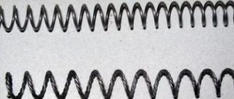
The holes are cylindrical, stepped, conical, shaped. The holes can be open on both sides (through) and on one side (blind). Drilling is a common method for processing blind and through holes in solid material with an accuracy of 12–13 grade and surface roughness Rz = 10…30 µm. Holes with a diameter of more than 30 mm are drilled in two transitions: first with a drill of a smaller diameter, then with the required diameter. There are two drilling methods: with a rotating drill (drilling and boring machines) and with a rotating part (lathes). To reduce drill drift, pre-drilling (centering) is performed with a short rigid drill. Drilling is carried out on lathes and automatic machines, as well as on drilling and boring machines with guide bushings. Drilling machines are divided into universal, specialized and special. On universal drilling machines you can perform any hole processing operations. Universal machines include: vertical drilling, radial drilling, tabletop drilling. Specialized machines include horizontal machines (cartridge and swivel type) for drilling and boring deep holes (swivel machines). If the specified accuracy of the hole is below the 9th grade, then depending on the diameter of the hole and the type of workpiece, subsequent processing is carried out by boring or reaming. The accuracy of the relative position of holes during sequential processing with different tools is achieved using a jig with replaceable bushings and quick-change chucks for securing the tools in the machine spindle. When drilling for threads, the diameter D of the drill is taken to be larger than the internal diameter of the thread d by the amount 2α = 0.3...0.4 of the thread height. Drills are divided into normal, deep drilling and special. Normal drills include spiral, feather and centering drills. For deep drilling (the ratio of hole length to diameter is more than five), feather drills are used. The drill consists of a rod up to 1.5–2.0 m long, which has two grooves for removing chips and two grooves for tubes supplying coolant with high pressure to remove chips. Grooves are made on the cutting edges of the plate to break and crush chips. In addition, this makes it easier for the cutting fluid to remove chips. Such drills are used for holes with a diameter of more than 30 mm. To make deep holes of relatively small diameters - up to 30 mm - twist drills with internal coolant supply are used. However, it is difficult to process deep holes with such a drill, since you have to often remove the drill from the hole to remove stuck chips and, in addition, it is not strong enough and provides less accuracy in the direction of the hole (increased drill drift occurs). Instead of spiral drills, it is advisable to use cannon and gun drills, which do not have a transverse cutting edge, which makes cutting metal easier. The top of the drills is offset by 0.25 diameters, thereby forming a cone that guides the drill. Drilling with such a drill is preceded by drilling to a certain depth with a twist or feather drill, which must be done very carefully to avoid the gun or gun drill being pulled away during subsequent deep drilling. The fairly small chips obtained when drilling with gun or gun drills are easily removed by coolant. The supply of coolant when drilling with a gun drill is carried out under strong pressure through a hole in the drill body, and chip removal occurs along the outer groove of the drill between the body (rod) of the drill and the machined surface of the hole. The disadvantage of gun and gun drills is their relatively low productivity. When drilling deep holes with a diameter of 80 to 200 mm and a length of up to 500 mm, ring drills are widely used. They cut out only an annular cavity in solid metal, and the cylinder-shaped inner part that remains after such drilling can be used to make other parts. Core drills come with several sets of spare HSS blades. Core drills can be used on turning, boring, turret and radial drilling machines that have a conventional coolant supply system. When drilling with such drills, productivity increases up to 4 times compared to drilling with twist or gun drills.
Figure 2 - Ring drilling
Countersinking is used to process a previously prepared hole by casting, broaching or drilling. The tool is a countersink. Countersinks, depending on their purpose, are divided into cylindrical and conical. Reaming is the main method of processing a hole of the 8th–9th accuracy grade (when processed with two reamers, the 5th–7th accuracy grade is reached) with a surface roughness Ra = 0.15...2.5 µm in a material with hardness HRC ≤ 40. Reaming – differs from a countersink in a larger number of teeth and smaller angles in the plan. Reamers are divided into manual and machine and are made solid and sliding. Hand reamers have long teeth and a long tapered part called a fence. Machine one-piece reamers are used for holes with a diameter of up to 30 mm. For holes with a diameter of more than 30 mm, in order to save cutting tool material, attachment reamers are used. Sliding reamers are used for diameters from 25 to 100 mm. Reamers with insert knives are widely used, used for diameters from 35 to 150 mm. A necessary condition for achieving high machining accuracy is the uniformity of the allowance removed and strict coincidence of the reamer axis with the axis of the hole being machined. During operation, the reamer must be freely positioned along the hole or have an accurate direction. When working with finishing reamers on lathes and turret machines, oscillating mandrels are used to compensate for the mismatch between the hole axis and the direction of the reamer.
Machining of shaft type parts
Round rods, the length of which exceeds three diameters, are usually called shafts. They can be smooth, stepped, with areas of complex shape, or hollow (Fig. 50). In addition, shafts whose length exceeds 12 diameters are called long.
The technological route for turning shafts is in most cases carried out in the following sequence:
1. Trimming the ends of the workpiece to length and centering on both sides.
2. Rough turning in the chuck and back center with an allowance for finishing precision surfaces of 1-2 mm per diameter.
3. Finish turning of precise surfaces in the centers.
Technological routes for processing shafts - long and with sections of complex shapes - are supplemented by some work due to their peculiarity (for this, see § 67 and Chapter XII).
Let's consider an example of constructing a technological route for processing a stepped shaft (Table 4) from round rolled steel Ø36X264 mm in the amount of 10 pieces. Screw-cutting lathe 1K62.
Figure 50. Types of shafts:
a - smooth; b, c - stepped; d- areas of complex shape; d - hollow
Adhering to the recommended sequence of mental actions (see Figure 49), we establish the required processing accuracy from the drawing.
The shaft has three cylindrical sections - Ø25f11, Ø22f11 and Ø28hl2, the accuracy of which is limited to 11th and 12th grades, respectively. Other sizes without tolerances are subject to processing according to the 14th quality.
The accuracy of the shape of cylindrical surfaces is not established in the drawing, therefore their errors should not exceed the tolerances for the corresponding diameters.
The accuracy of the relative position of surfaces Ø25, Ø28 and Ø22 mm is limited to radial runout relative to the common axis of no more than 0.08 mm.
Surface roughness (except for those indicated on the contour of the part) - Rz≤40 µm.
The part is not subjected to heat treatment. Consequently, its complete processing (with low dimensional accuracy) can be performed on a lathe.
The workpiece is round rolled steel for one part, has allowances for diameter and length of 4 mm; its curvature is within acceptable limits.
To produce a small batch of parts (10 pieces), we build the technological route step by step with a small degree of dissection.
According to the technical characteristics (see Chapter VIII, Table 9), the 1K62 screw-cutting lathe allows you to efficiently process parts.
Processing methods are selected based on the principle of greatest productivity. It is advisable to trim the ends using the most durable bent cutter. Precise cylindrical sections Ø25, Ø28 and Ø22 mm should be processed by roughing and finishing turning. It is advisable to process all other surfaces that have free dimensions only by rough turning in the least number of working strokes.
For final processing of those sections of the shaft that must have an exact relative position, a single technological base is adopted - center holes. The technological basis for cutting and centering the ends is the cylindrical surface of the workpiece. Considering the low rigidity of the shaft, it is advisable to perform rough turning when installing it in the chuck and the rear center; i.e. here the technological base will be the cylindrical surface of the workpiece and the center hole.
According to the selected technological bases, methods for installing workpieces on the machine are adopted: in the chuck, in the chuck and the rear center, in centers.
Taking into account the size of the processed batch of parts and practical rules for completing transitions in operations, we divide the technological route into 6 operations: 1-2 - trimming and centering the ends in the chuck; 3-4 - rough turning of the shaft on both sides in the chuck and the rear center; 5-6 - finishing grinding of precise surfaces in the centers.
Table 4
Technological route for turning a stepped shaft
| operation | Installation | Transition | Contents of settings and transitions | Installation diagrams |
| A | Install and secure the workpiece | |||
| in the cartridge | ||||
| Cut the end to size 2 | ||||
| Center to size 1 | ||||
| A | Install and secure the workpiece | |||
| in the cartridge | ||||
| I | Cut the end to size 2 | |||
| Center to size 1 | ||||
| A | Install and secure the workpiece | |||
| in the chuck and center | ||||
| Grind cylinder 3 | ||||
| Grind cylinder 4 | ||||
| Grind chamfer 2 | ||||
| Make groove 1 | ||||
| A | Place and secure the workpiece in the chuck and centers | |||
| Grind cylinder 5 | ||||
| Grind cylinder 3 | ||||
| Grind cylinder 4 | ||||
| Grind chamfer 2 | ||||
| Make groove 1 | ||||
| A | Install and secure the workpiece in the centers | |||
| Grind cylinder 2 | ||||
| Grind cylinder 1 | ||||
| A | Install and secure the workpiece in the centers | |||
| Grind cylinder 1 |
Test questions and assignments:
1. What parts are usually called shafts?
2. Give a typical technological route for processing shafts.
3. Complete task No. 101
Grinding
Grinding is the main and most common method for processing external cylindrical surfaces. Divided into fine and fine grinding. Fine grinding is carried out with grinding wheels or grinding belts on cylindrical grinding machines with longitudinal feed and the plunge method, on centerless grinding machines with a pass and the plunge method, as well as on belt grinding machines. On a cylindrical grinding machine, the workpiece is mounted at the centers of the machine. The linear speed of the rotating workpiece is 10–15 m/min, and the linear speed of the tool (grinding wheel) is about 30 m/s. The grinding process can be carried out with longitudinal feed and plunge method. In the first case, the workpiece undergoes reciprocating longitudinal movement with longitudinal feed Spr = (0.5 – 0.8) N, where H is the height of the circle, per revolution of the workpiece, and at the end of each stroke a transverse feed is made (depth of cut) 0 .01–0.03 mm. During nursing passes, the longitudinal feed is reduced to Spr = 0.2...0.3N, cutting depth to 0.005...0.02 mm. The length of the longitudinal stroke during grinding should ensure that the tool overtravels to one side equal to 0.2 - 0.4 N, where N is the height of the wheel or the width of the belt. The second method is that the tool (grinding wheel or sanding belt) is only given a transverse feed per revolution of the workpiece. Finish cylindrical grinding at the centers of the machine ensures 6–7th grade accuracy and surface roughness Ra = 0.3…1.25 µm. Fine cylindrical grinding in the centers of the machine ensures accuracy of the 5th–6th grade and surface roughness Ra = 0.02…0.08 microns. When grinding on pass-through centerless grinding machines, the workpiece is placed between two grinding wheels on a special supporting knife made of wear-resistant material. Thanks to the bevel directed towards the drive circle, the part is pressed against the drive circle, as a result of which the drive circle transmits torque to the part. To avoid cutting, parts with a diameter of more than 30 mm are shifted upward by 10–15 mm from the line of the centers of the grinding wheels. When grinding on a pass, the driving wheel is set at an angle α = 1...5°. The amount of longitudinal feed S during grinding per pass is prescribed in the range of 400–4000 mm/min. Linear speed of the driving wheel Vв.к = 15…30 m/min during rough grinding. When finishing grinding, increase to 100 m/min or more.
METAL STRUCTURES
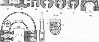
Center machining must be performed with the workpiece correctly centered. On centered workpiece 1 ( Fig. 268
) put on the clamp 2 and secure it with screw 4, after which the workpiece is installed on the centers without play.
Rice. 268
Rotation from the machine spindle to clamp 2 and workpiece 1 is transmitted through drive chuck 3 screwed onto the threaded part of the spindle. The types of center holes are shown in Fig. 269
.
Rice. 269
. Types of center recesses: a - with a single cone; b - with a double cone; c - with double cone and thread
The front center, mounted in the conical bore of the spindle, rotates with the workpiece. Rear center ( Fig. 270, a
) is installed motionless in the tailstock quill, and the workpiece, during its processing, rubs with the center recess along the center cone, wearing it out.
Rice. 270
.
Turning
centers: a - simple; b - cut “half-center” with a ball; c - with a ball tip; g - reverse center; d - rotating center
In order to reduce wear on the rear center, the center recess of the workpiece is lubricated with grease, and a hard alloy is deposited on the working end of the rear center. When working at high speeds, use a rotating rear center ( Fig. 270, b
).
In addition to the simple and rotating centers, a cut center ( Fig. 270, c
) is used, a half-center when trimming the end, a center with a ball tip (
Fig. 270, d
) when turning a conical surface in the centers by displacing the tailstock, and a reverse center (Fig
. 270, d
) when turning small-diameter workpieces (up to 5 mm), the ends of which are made conical for installation in reverse centers. When turning the centers of smooth shafts, first cut one end and grind the end of the shaft to a sufficient length to install the clamp. Then the shaft is turned over, the second end is trimmed and the cylindrical surface is ground.
Turning of stepped shafts can be done in different ways. In Fig. 271
2 ways of processing stepped shafts are shown.
Rice. 271
. Methods for turning a stepped shaft: a - first method; b - second method
Trimming the ends in the centers is carried out with a transverse feed using special scoring cutters when installing the workpiece in the “cut” center ( Fig. 272, a
) or when centering a workpiece with a double cone and when fastening it in a simple center (
Fig. 269, b
and
272, b
).
Rice. 272
. Trimming ends, turning grooves and fillets
Fillet
(rounding between two cylindrical surfaces) can be turned by turning a cylindrical surface with a straight cutter that has the necessary rounding of the cutting blade;
sometimes the fillet is turned with a special cutter ( Fig. 272, c
).
The grooves are turned with a cutter of the appropriate shape with a transverse feed. Wide grooves are turned with the same cutters, first with a transverse and then with a longitudinal feed.
Treatment
in centers and
rests
is performed in order to avoid
turning
. During processing on the centers, the workpiece bends under the influence of the radial component of the force Ru. If the workpiece is long, after turning the diameter in the middle is larger than at the edges. To eliminate (or reduce) the amount of deflection, the installation of blanks in the center and movable or fixed rests is used.
Fixed rest
(
Fig. 273, a
) is installed on the guides 4 of the frame and attached to it with a bolt 3. The workpiece 2 in the steady rest is supported by cams 1 or rollers, adjustable with screws.
Rice. 273
. Lathe rests: a - fixed; b - movable
Movable steady rest ( Fig. 273, b
) moves with the support 4 and is attached to it on the back side of the workpiece 3. Two cams 2 of the steady rest are brought close to the workpiece with screws 1 and prevent the workpiece from deflecting.
Machining in jaw chucks is used for workpieces with holes and large end surfaces (flywheels, pulleys, bushings, etc.).
Simple four-jaw chucks ( Fig. 274, a
) have independent movement of each cam 4 from a separate screw 5. This movement of the cams allows you to install and secure both cylindrical and non-cylindrical workpieces with the required accuracy.
Rice. 274
. Jaw chucks for lathes: a - four-jaw; b - three-jaw “self-centering”
Self-centering three-jaw chucks ( Fig. 274, b
) are driven by a small conical wheel 2, which rotates a large conical wheel 3, on the reverse side of which there is a face thread (Archimedes spiral) 4. Three cams 1 move simultaneously in the grooves of the cartridge. The movement of the cams 1 in the radial direction of the cartridge body allows you to install and secure exactly along the spindle axis, a workpiece with a cylindrical outer or inner surface.
Mandrel machining is used in cases requiring the outer surface to be concentric with the hole.
Processing with combined fastening is used for relatively heavy workpieces. One end of the workpiece is fixed in a jaw chuck, and a fungus supported by the center is inserted into the hole of the second end ( Fig. 275, a
), and grind the outer surface almost to the chuck jaws.
After this, the workpiece being processed is turned over, installed in the chuck jaws and a fixed rest ( Fig. 275, b
), then ground on top, the end is trimmed and the hole is bored.
Rice. 275
. Turning with a combined method of fastening workpieces: a - in a chuck supported by a “fungus”; b - in the chuck and rest
Drilling
,
countersinking
and reaming on
a lathe
are performed manually by feeding the tailstock quill along with the tool inserted into it. Sometimes a drill, countersink or reamer is fed mechanically using a caliper.
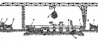
Features of processing heavy engineering parts
Heavy engineering includes the production of metallurgical equipment (for example, rolling mills), large metal-cutting machines, powerful hydraulic, steam and gas turbines, electric generators, large excavators, etc. Processing techniques used in heavy mechanical engineering are also used when processing large parts at factories in other branches of mechanical engineering and partly in workshops for processing basic parts in medium-sized mechanical engineering. Since large machines are manufactured in very small quantities, production is organized as single or small-scale production. In the manufacture of large machines, universal equipment and simpler technological equipment are most often used than in mass production. Due to the large weight of large workpieces and parts (up to 300 tons), intra-shop transport becomes of great importance. The main means of transport in heavy engineering workshops are usually overhead cranes, the lifting capacity of which reaches 250 tons and above. In some cases, particularly heavy parts are lifted and moved by two cranes at the same time. When designing heavy machine tools, efforts are made to avoid moving heavy parts from operation to operation and during processing. For this purpose, mobile portal machines with milling heads, mobile boring columns, single-sided milling machines in which a milling cutter with a diameter of up to 2 m has a feed, large rotary machines for turning parts with a diameter of up to 18 m, heavy multi-slide lathes for turning parts up to 30 m in length are used. and with a diameter of up to 2 m. In the course of the development of heavy engineering technology, a system of so-called “bench processing” was developed, that is, if the processing machines are lighter than the workpiece, then it is easier and cheaper to move the machine to the workpiece than the workpiece to the machine. Bench processing is carried out using horizontal drilling and boring and portable machines moving along the stand, supplied to the stand by a crane. Portable machines are used: drilling machines - with a drilling diameter of up to 60 mm, radial drilling machines - with a drilling diameter of up to 75 mm, cross-planing machines - with a slide stroke of up to 1500 mm, slotting machines - with a slide stroke of up to 2000 mm. When manufacturing basic parts (beds, frames, frames, etc.), combined bench processing accounts for up to 60% of the total labor intensity and reduces the processing cycle by 1.5–2 times. When bench processing, adhere to the following rules.
- The time for installing each additional mobile or portable machine to the parts should be less than the time required to reinstall the workpiece on another machine.
- Mobile and portable machines should be placed around the part so that parallel operation of the machines can be organized and the machine on which the work has been completed can be removed without interfering with the work of other machines.
- Heavier mobile machines must handle more work than lighter portable machines.
- The technological process maps must contain all the necessary instructions about the procedure for processing with mobile, portable machines and how to install them on the stand.
- All necessary equipment for mobile and portable machines should be prepared. It must be submitted to the stand simultaneously with the machines.
- While a part is being processed at one place on the bench, another workpiece is being prepared for processing at an adjacent place on the bench.
To improve the conditions for processing heavy parts, additional equipment (improvement) of the workplaces of universal machine tools is used, the purpose of which is to expand the technological capabilities and improve the use of the equipment.
Additional pits and ditches are installed near the machines, in which workpieces that do not fit on the machine plate can be processed. Additional plates are made on radial drilling machines, on which it is possible to prepare the processing of one workpiece while processing another. Radial drilling machines are mounted on a trolley that moves along a long workpiece. Figure 3 - Construction of a hole on a radial drilling machine
Machine tooling for turning
In addition to the main components of the equipment, in some cases special equipment will be needed to perform turning work. It can be included as standard on the machine, or installed as an option. In this case, turning can be performed in non-standard modes.
One of the defining components is the parts fixation mechanisms. Traditionally, the workpiece can be mounted between the headstock and the rear drive stock. This takes into account the configuration of the locking chuck, as well as the parameters of the tailstock quill.
To increase the functionality of the equipment, the following additional components of the lathe can be used:
- clamps. Designed to transmit torque when securing parts in centers;
- pressure Installed on the tool holder and is necessary to increase the accuracy of tool positioning;
- lunette. Used for turning work with large workpieces. This device serves as an additional fixing element.
In addition to these devices, various others can be used. It all depends on the requirements for the quality of operations, as well as the parameters of the processing flow chart.
As an example, you can watch a video that shows high-tech turning of a part: