Welding metal workpieces is not only about working with an electrode or a gas torch. These are several positions that affect the quality of the final result. Namely: preparing the metal for welding, setting up the welding machine with the choice of welding mode and, of course, the technique of carrying out the process itself. There are a few more points, but they are less significant.
So, what is included in the concept - preparing parts for welding. There is a fairly large list of operations that facilitate the process itself and increase the quality characteristics of the weld. The preparatory process before joining metal workpieces includes:
- editing;
- marking;
- if necessary, bending of workpieces;
- cutting and cleaning the edges of welded parts;
- assembly of structures before starting connections.
All operations are significant, so we need to analyze them in more detail.
Edit
During storage and transportation, parts of the future welded joint may lose their shape. Distortions include:
- dents;
- bulging;
- warping;
- waviness;
- curvature.
Correct metal cold and when heated. Corrections of heated metal are easier. Editing can be done either by machine or manually. The machine method is used in industry. It is convenient to carry out manual editing using an anvil. Thick steel or cast iron plates are also suitable.
To carry out the straightening process, it is necessary to prepare a metalworking tool. First of all, you can return it to its original shape using a hammer. However, not just any one will do, but one made of soft material. In some cases, you can even use rubber. The shape of the striker is preferably round - a square one will leave marks on the metal. The surface of the striker must be polished. In addition to a hammer, you can use a wooden or metal smoother.
Convexity and undulation are corrected by hitting the edges and gradually moving towards the center. As you approach the central part, they strike more often, but the force of the strikes is reduced. To adjust thin products, it is advisable to use smoothing bars. The straightening of hardened metal is carried out with a straightened hammer.
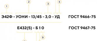
Designations on the drawings
The main types of edge preparation for welding are not indicated in the drawings. When designating a weld seam, the drawing indicates the regulatory document in accordance with which the seam is made, as well as the type of connection itself, its symbol. You can read more about how welding seams are designated in a drawing in our article - How welding seams are designated in drawings - welding symbol.
Marking
Preparing metal for welding includes bringing the dimensions of the parts into line with those indicated in the drawings. Before you start cutting, you need to mark them. For marking, use a sharp object, chalk, pen, thin felt-tip pen, or pencil. Tools you will also need are a ruler, tape measure, square, and caliper. In large production, templates are used.
In addition to the outline of the parts, the places of bends are marked on the metal part.
Welding Preparation Tips
Following best practices can help you optimize the results of weld preparation, cleaning and grinding.
- Reduce the grinding angle: When using a grinding wheel, reduce the grinding angle. This will help you achieve maximum control and reduce the risk of overcutting. The outer angle of the grinding wheel is the most aggressive, so the steeper the entry angle, the more likely it is that the wheel will remove more surface material than required and ruin the workpiece. A shallower grinding angle helps improve control and reduce the risk of material damage.
- Watch your blood pressure. If you are using wire wheels, remember that only the ends of the wire are meant to work. Pressing too hard may cause the wire to bend so that the ends no longer touch the material.
- Use sequential passes. Enter the grinding pass by pulling on the tool rather than pushing it to control the aggressiveness of the grinding wheel. Sand according to the material, using smooth, even strokes rather than short, choppy strokes. This provides effective results with coated abrasives (sandpaper) and bonded abrasives (sanding wheels).
- Avoid sanding by hand. When you use only your hands to operate the grinding wheel, the vibration of the wheel can take a toll on your wrists and forearms. Instead, use the large muscles of your body to move and control the angle grinder. To minimize fatigue, move your entire body in the direction of movement, not just your arms.
Proper cleaning and preparation of the material is a critical first step in producing high-quality welds. Remember that when you prepare to weld, you want to remove contaminants from the surface, not excess material. Selecting the appropriate weld preparation abrasive and following best practices will help you achieve the results you want.
cutting
This is one of the most important stages in preparing metal for welding. A metal element cut downwards can be immediately classified as defective. It's good if there is an opportunity to use it for other purposes. It is not very successful if an adjustment of a few millimeters is required, since such a process is quite difficult to carry out.
Cutting Tools:
- metal scissors;
- guillotine;
- Bulgarian.
For thick parts, welding can be used. To do this, you need to melt the part, and then remove the metal so that you get not a seam, but a through hole. If you follow the intended line, you will get a cut, although not too neat. Thermal cutting is applicable for parts of various configurations. Arc welding and oxygen torch are widely used.
Cutting machines are used in industrial production.
Make a plan
To properly prepare for welding, it is important to have a plan before you begin. Otherwise, you can easily become completely immersed in a project that seems simple, only to quickly discover that there are many factors that can lead to costly costs, extra steps, or rework.
Consider these questions when developing your welding preparation strategy:
- What is required for the welding process I use? If you perform submerged arc welding (SMAW), you can often avoid contamination of the surface of the material, but the process requires additional cleaning after welding and between passes. Metal arc welding (MIG/MAG) and gas tungsten arc welding (TIG) typically require more preparation and a cleaner surface to produce quality welds, but also require less effort to clean up after welding.
- What is the best way to prepare the material I am working with? Some materials, such as hot rolled steel, have heavy mill scale on the surface that must be completely removed before welding. Harder materials such as INCONEL alloys require high performance abrasives such as ceramics in preparation for welding. Soft and non-ferrous metals such as aluminum may be more susceptible to pressure on the grinding wheel, causing it to clog. In this case, particles of the base material adhere to the grinding wheel, and an abrasive is required to prevent the grinding surface from becoming clogged with the material being processed.
- What are the finishing requirements? When choosing an abrasive, it is important to know and understand the processing requirements.
Stripping
Preparing metal for welding includes cleaning it. Failure to complete this step will result in defects. Even small particles of dirt can cause cracking of the part, the appearance of pores in the structure of the weld, and the emergence of stress spots in the metal.
Cleaning metal surfaces is the easiest preparatory process, but it is very important. You don't need any particularly complex tools. Metal brushes and grinders are used. In production, this process is taken more seriously and shot blasting and sandblasting machines are used.
We should not forget about the need to remove rust, as well as the oxide film, which is formed when the metal comes into contact with atmospheric oxygen. To remove traces of paint and oil stains, a small part can be immersed in a container of solvent. The metal surface must be dried before welding.
Choose the right abrasive profile
There are several abrasive profiles available to you that can make your job easier or more difficult.
Wire wheels are much more resistant to stress, but do not remove the underlying material. This makes them a good choice for removing surface contaminants and coatings without affecting the underlying metal. Abrasives are designed for cutting and removing base metal. Due to the design of the abrasive, heavy coatings and base metal can accumulate between the grains, reducing their cutting ability.
A Type 27 flap disc (flat profile) may produce a significantly different result than a Type 29 (tapered profile). An incorrect profile actually limits the amount of abrasive that comes into contact with the metal surface. Select Type 27 flap discs for lower grinding angles (5 to 10 degrees) and for light pressure applications such as finishing. When sanding at larger angles (15 to 30 degrees), choose a 29-type flap disc, which is more typical for aggressive material removal.
Wire brushes also come in different styles and sizes. Wire gauge and knot type are the most effective performers. Options include stringer, cable and standard twist.
- The stringer brush has knots that are twisted very tightly into a narrow profile. This brush is designed for cleaning tight gaps and initial welds on pipelines and multi-pass welds. They are also commonly used in general manufacturing
- A cable twist brush has a knot that is twisted almost all the way through, with more wire in the knot so it has extra width, stiffness and aggressiveness. This can be significantly more efficient for weld preparation if you don't have to specifically go into a narrow 3mm gap
- The standard twist brush assembly is not twisted all the way to the end, allowing the wire tips to fluff out for increased fit. These brushes are effective on components with a lot of surface, texture or contour imperfections. Inexperienced operators often get the most effective cleaning with a standard twist brush because it covers a wider area and is easier to control.
Edge preparation
To improve the conditions of the welding process, the edges of the product are processed. This is especially important when welding thick products. Preparation of edges for welding can be done by thermal and chemical methods. The result of processing is the acquisition of a shape that promotes better connection of parts. Grooving increases the width of the seam.
Milling machines, special edge planers, pneumatic chisels, and flame cutting are used in industry. Simpler options are grinding and cutting. For mechanical cutting, metal scissors, a grinder, a chisel, and a file are used. The main parameters are the bevel, cutting angle, gap width, and the amount of bluntness. A bevel is formed when a piece of metal is removed at an angle or rounded.
If welding is performed at an angle, then cutting the edges can be carried out only when the thickness of the parts is more than 3 cm. The presence of a bevel plays an important role when parts of different thicknesses are welded. Sometimes you have to resort to dulling the edges. This is advisable if they have a sharp shape at the end. Otherwise, this may cause the formation of burns, deformation of the seam, the creation of additional stress, and a decrease in the strength of the connection.
The cuts can be on one side only or double-sided. Different types of bevels are used for different connections:
- The one-sided bevel of one or both edges has the shape of the letter “V”. Suitable for use in a wide range of thicknesses. Is the most popular. When cutting both edges, the angle is 60 degrees, and only one - 50.
- The double-sided bevel of both edges resembles the letter "X". Used for products with a thickness of 10-60 mm. Angle - 60 degrees.
- The bevel in the shape of the letter "U" is made on one side. This curved shape is used for metals with a thickness of 20-60 mm. For beginners, the method is difficult.
- A bevel in the shape of the letter “K” is rarely used. In this case, a double-sided bevel is made for one of the edges, and a one-sided bevel for the second.
The designation on the drawings is for the bevel “β” and the opening angle “α”. The bevel should not have any differences. Templates can be used to control cutting.
A separate option is preparing edges for welding pipes. In this process, it is necessary to control the perpendicularity of the end of the pipe to its axis. The requirements are set out in the regulatory document RD 153-34.1-003-01. The total opening angle formed by the two circular edges of both pipes is 60-70 degrees. Blunting is done at a size of 2-2.5 mm.
Preparation of pipes for welding involves gradation according to the wall thickness of the pipes being welded. For small sizes, V- or X-shaped bevels are used. For larger thicknesses, a U-shaped bevel is made.
Preparing pipes for welding also involves discarding. Welding is unacceptable if the difference in the internal diameters of the pipes prepared for welding is more than 3 mm. If the ends have mechanical defects, they are trimmed.
04/08/20 942 RPS “Assembly of parts for welding”
In workbooks, prepare the report in the form of a short summary according to the plan (only in bold).
I'm waiting for photo reports of the work done.
After studying the lecture, take the online test.
LECTURE TOPIC:
Boring of parts for welding.
PLAN:
- Types and methods of assembly.
- Assembly rules.
- Types and purpose of assembly, technological devices and equipment.
- Types and methods of assembly.
The labor intensity of assembling parts for welding is about 30% of the total labor intensity of manufacturing the product. To reduce assembly time, as well as to increase its accuracy, various devices are used.
Assembly for welding can be performed in the following ways:
complete assembly of the product from all its constituent parts, followed by welding of all seams;
alternately attaching parts to an already welded part of the product - if it is impossible to use the first method;
preliminary assembly of the units that make up the product, followed by assembly and welding of the product from the assembled units; this method is the most rational; it is used in the manufacture of large and complex structures (ships, carriages, bridges, etc.).
2. Rules for assembling structural elements for welding.
In general, assembly is a set of operations to install parts in the position specified in the drawing for subsequent welding.
The main goal of developing an assembly process is to determine the most advantageous sequence and method of assembling individual parts, ensuring that the technical requirements for the manufacture of a given product are met with minimal labor, time and auxiliary materials. When developing this process, one should strive for maximum mechanization of assembly work through the widespread use of various kinds of power tools, working and control devices. It is necessary to strive to eliminate the operations of fitting, filing, and drilling in place.
Depending on the type of product, certain technical requirements for assembly are established. From a welding point of view, a requirement included in the technical specifications is to ensure certain design parameters of welded joints. Thus, a specific feature when assembling parts joined end-to-end by fusion welding is the observance of certain gaps between the welded edges. The size of the gaps depends on the thickness of the elements being connected and is established by standards or GOST.
When assembling parts with an overlap before resistance welding (TES and RES), a necessary requirement is the complete elimination of gaps. According to the standards adopted in production, these gaps should not be more than 10% of the thickness of the thinnest part to be welded and exceed 0.1 ... 0.5 mm.
The assembly technological process is characterized by a certain labor intensity, as well as a certain time, called the assembly cycle, during which this process is carried out. The complexity of assembly depends on the degree of perfection of the design, the development of the technological process, the degree of interchangeability of the assembled elements and their accuracy, the power supply of equipment and equipment. Assembly cycle:
C = T/p,
where
T is the labor intensity of the process, h;
n
is the number of workers simultaneously employed in the process.
Obviously, the reduction in cycle is influenced by a decrease in labor intensity and especially an increase in performers. The latter depends on the design, scale of production, level of technology and production organization. Dividing the structure into units makes it possible to expand the scope of work, which also increases the number of workers employed in the assembly.
The size of the assembly cycle is greatly influenced by the choice of assembly process scheme. The assembly process diagram is the accepted sequence of assembling assembly units and connecting them into products.
In the production of welded structures, sequential assembly and welding of elements, complete assembly of the entire structure with its subsequent welding, parallel-sequential assembly and welding are used.
The sequential scheme (Fig. 1,
a) is advisable when assembling structures that are not divided into subassemblies, when welding of a fully assembled structure is impossible, and other schemes cannot provide the necessary accuracy due to the design features, for example, due to its insufficient rigidity.
It is performed by sequentially building up individual elements. The required accuracy can be achieved by using intermediate editing operations. Assembly and welding with such an organization of the process are less productive, since when they are performed sequentially, the scope of work is limited and the number of workers is reduced.
Rice. 3.18. Assembly diagrams for welded structures:
I,
II , III, IV— design details; 1-6 - technological operations
The scheme of complete assembly of a structure with subsequent welding (Fig. 1,
b) is usually used for relatively simple products or products of medium complexity, consisting of a small number of parts with easily accessible connections.
According to this scheme, the structure is first completely assembled, securing the elements with clamps, fasteners, and tack joints, after which the assembled structure is transferred to the welding area to weld all connections.
At the same time, the scope of work expands, the C
decreases. The scheme is used for various types of production. The technological process of assembly and welding, depending on the production program, weight and configuration of products, can be mechanized or fully automated.
The parallel-sequential circuit (Fig. 3.18,
c) is used in the manufacture of complex structures, divided into enlarged assembly units.
First, enlarged assembly units are assembled and welded on parallel production lines.
Then the finished units are assembled and welded into entire structures. With this scheme, the number of simultaneously employed workers or the scope of assembly work is much greater, so C
is minimal. Practice shows that such a circuit can reduce the cycle by 3...4 times compared to a sequential circuit. This confirms the great advantages of dissected structures. However, the number of assembly units must be selected based on economic feasibility. When assembling and welding structures, it becomes possible to widely use mechanization and automation of technological operations. With this scheme, the accuracy of manufacturing products increases, and the overall deformations of the entire structure are reduced, since the rigidity of the units is always greater than the rigidity of the individual parts. In addition, it is easier to straighten deformed components than a fully welded structure. This, in turn, helps improve the quality and reliability of products. The scheme is used in various types of production. Thus, by skillfully developing a scheme for assembling products, you can influence the duration of the process and reduce labor intensity.
The content of the technological operations of the assembly processes of structures, in turn, is determined by the methods of basing and assembly used, on which the accuracy and interchangeability of the assembled product, the content of assembly work, and the composition of assembly tooling and equipment depend.
Depending on the type of production, design features and technical conditions, assembly can be performed in various ways: by markings, by templates or the first product, by assembly holes, in fixtures (universal, specialized and special).
Assembly according to markings is carried out without devices. The location of the parts is determined by markings according to the drawing. Then they are secured with clamps, removable clamps, potholders, etc. The productivity of the method is low; it is used in single production for the manufacture of simple products. Achieving the specified accuracy during assembly is possible only with a large expenditure of highly skilled labor. Using templates or the first product to assemble can improve productivity.
Assembling components using assembly holes is a progressive process that allows for high economic performance of assembly work and sufficient accuracy. An obstacle to its widespread use is the design of the connections, which often makes it difficult or completely impossible to use assembly by holes. Therefore, it is necessary to provide for the assembly method already during the structural development of the product and testing its manufacturability. When assembling using assembly holes, the specified arrangement of product parts is achieved by using the holes as assembly bases for parts. Assembly holes serve to coordinate and fix parts of the product and are usually assigned from among the holes included in the connection, which is very rare in welded assemblies. In such products, existing structural holes can be used as assembly holes. Sometimes they can be designed as technological with subsequent removal by welding or riveting (Fig. 3.19, a).
Holes are drilled along overhead jigs. Assembly using assembly holes simplifies assembly equipment, but requires end-to-end coordination of the dimensions of the parts. For thin-sheet elements, instead of holes, special stampings can be used.
The greatest assembly accuracy with minimal labor intensity can be achieved with special assembly equipment, usually used in large-scale and mass production.
Rice. 3.19. Assembly by holes:
A
— panels:
1
— casing;
2
— stiffening element;
3—
latch;
b
— bracket: / — body;
2
— bracket;
3
- latch
In production conditions with a small production program, universal and specialized devices of medium complexity are used.
In addition to assembly equipment, the quality of workpieces has a decisive influence on the labor intensity of assembly work. In the absence of interchangeability of parts, assembly is complicated by the need to perform fitting operations. When performing technological operations, even under conditions of the strictest technological discipline, abnormal side changes occur in the processed objects, many of which can have a significant impact on the quality of the product. For example, deviations in the shape and size of sheet parts due to elastic stresses arising during bending, drawing and other shaping processes, or the appearance of residual stresses in welded parts.
Non-standardized changes in the properties of production objects that occur during the performance of individual operations of the technological process are one of the reasons for the instability of product quality. The presence of such deviations will, first of all, affect the quality of assembly and welding work. There is a need to carry out adjustment operations during the assembly process. The presence of fitting operations is, first of all, the result of the non-interchangeability of structural elements, therefore interchangeability is the most important prerequisite for ensuring high quality of structures in general. A structural element is interchangeable if its geometric and physical parameters are within the agreed tolerances
with the tolerances of other assembled elements. With such coordination, the need to select or modify elements during assembly is eliminated and the assembly of the entire structure is ensured in accordance with the established technical conditions.
When performing assembly work, there are methods of complete, incomplete, group interchangeability and assembly with fitting of parts. According to the first method, assembly is carried out by connecting parts without any selection, adjustment and other additional work, in full compliance with the technical requirements for the product. The required accuracy of parts is determined by the corresponding tolerances on their dimensions. This method is more often used in the serial production of structures whose elements are subject to preliminary mechanical processing.
Assembly using the method of incomplete interchangeability occurs when one of the connected parts of the dimensional chain is modified during assembly operations, when using compensators. This method is widely used in the aviation industry, automotive industry and other industries. By modifying one of the parts or introducing a compensating element, deviations of parts from the nominal dimensions of the dimensional chain are eliminated and the specified assembly accuracy is ensured. This makes it possible to reduce the requirements for the accuracy of all assembled parts and increase the accuracy of the product without resorting to a large amount of labor-intensive manual fitting and finishing work.
The group interchangeability method involves sorting the assembled elements into groups. The tolerance range of each group is 1 /n
part of the total tolerance field of mating parts
(n is
the number of groups). During assembly, parts of only the corresponding groups are connected to each other so that the resulting overall tolerance for assembly dimensions satisfies the specified accuracy of the product. The use of such selective assembly makes it possible to assign wider tolerances to manufactured parts and at the same time achieve high precision designs. The method is used in large-scale and mass production.
Assembly using the fitting method is carried out by individual modification and adjustment of each of the connected parts. The fitting method is used in single, small-scale production, when it is not economically profitable to have complex technological equipment for manufacturing parts with high precision. Assembly is carried out in two stages, preliminary assembly is introduced for the purpose of fitting and assembling parts. Due to the inevitable contamination of parts during fitting work, after preliminary assembly, the assembled product is disassembled and transferred to operations for preparing the surface of parts for welding. Thus, the surface treatment of parts is carried out after preliminary assembly. The fitted and prepared parts are sent for final assembly for welding. The double assembly method is often used in the manufacture of products from thin-sheet stamped parts, in which it is not always possible to ensure their high interchangeability, especially in single production. Double assembly is sometimes necessary in the manufacture of critical products, such as aircraft fuel tanks, to remove chips from the assembled assembly that formed during fitting.
3. Types and purpose of assembly, technological devices and equipment
. For the assembly and welding of columns, beams, racks of complex cross-section, as well as sheet structures made of steel with a thickness of more than 8 mm, devices are used that allow some movement of structural elements during shrinkage of the weld metal.
Devices can be intended only for assembling parts for welding or only for welding already assembled parts. Combined assembly and welding devices are also used.
An idea of the design of assembly and welding fixtures is given in Table. 9.
Electromagnetic stands are convenient for assembling sheet structures, which record the position of the edges of the sheets being welded (Fig. 1). Electromagnetic stands can be used to assemble and weld sheets up to 15 mm thick. The disadvantage of this type of device is the negative influence of the magnetic field on the welding arc during the welding process.
Rice. 1. Magnetic stand: 1 - electromagnets, 2 - sheets to be welded
In the mass production of identical structures, specialized assembly jigs with mechanisms for clamping parts are used. In these jigs, parts are assembled and tacked, then the product is released from the jig and fed to a site or stand for welding.
The assembly accuracy is checked using templates and probes (Fig. 2).
Rice. 2. Tool for checking the quality of assembly: a - angle of opening of the edge, b - right angle, c - displacement of sheets, d - gap between sheets when lap welding, e - gap when welding v-tee and butt welding
Internet resources used:
- https://metallurgu.ru/books/item/f00/s00/z0000015/st032.shtml
- https://osvarke.net/rabota-s-metallom/podgotovka-i-sborka-detalej-pod-svarku/
- https://studref.com/622473/tehnika/sborka_svarnyh_konstruktsiy
Bending
Preparatory and welding work includes, if necessary, bending of metals. If the parts are in the form of sheets or strips, then sheet bending machines are used. Parts with a profile are bent using special presses.
If it is necessary to bend a small diameter, as well as with a large thickness, then preheating is recommended. This will make the metal more pliable and less effort will be required.
Selecting gas welding modes
When choosing gas welding modes, they are guided by the grade of the metal or alloy being welded and its thickness. And also the type and purpose of the product being welded. The main characteristics of the gas welding mode include: the power of the welding torch, the type of gas flame, the brand and diameter of the filler rod or wire, the gas welding method and welding technique.
Selecting the power of the welding torch
The thermal power of a welding torch is determined by the flow rate of acetylene passing through it. The required acetylene consumption can be determined by the formula:
Q=AS, where Q is acetylene consumption, l/h; S—thickness of the metal being welded, mm; A is a coefficient that is calculated empirically. When welding carbon steels, coefficient A=100-130l/(h*mm); when welding copper A=150 l/(h*mm), when welding aluminum A=75 l/(h*mm).
The recommended flame power for the right-hand gas welding method is determined by the acetylene consumption of 120-150 l/h, and for the left-hand welding method the acetylene consumption is determined at the rate of 100-130 l/h per millimeter of thickness of the metal being welded.
It must be borne in mind that an increase in acetylene consumption leads to an increase in the power of the welding torch. But if its power is excessive, there is a risk of burning through the metal. The power must be optimal and this must be taken into account.
The power of the gas flame is regulated by replaceable tips that come complete with welding torches.
Fixation
Preparing parts for welding includes securing them securely to each other. This will ensure the correct position when welding and prevent them from shifting. A method that guarantees reliable fixation is tack welding. This refers to small seams made across the connection of parts.
The size of their section is limited - it should not exceed half the width of the seam. The length of each tack is no more than 2 cm. Pipeline assembly involves making longer tacks. The distance between them is from 10 to 80 cm depending on the length of the seam. The step size also depends on the thickness of the materials. For short seams, point joints are used at their edges. The height of the tacks should not be too high.
Small seams prevent movement of parts in joints, maintain a constant gap between them and give the structure additional rigidity. This is especially important for large connections. Tacks are performed in one pass.
Tacks are divided into temporary ones, which are removed after the weld is completed, and those that remain. They are performed on the reverse side of the connection. Before starting the process, it is necessary to do the same cleaning of the surfaces as for the main seam.
Tack workpieces
This process is required to secure the prepared parts before welding. As a result, they will be in the correct position after the work has been carried out. In most cases, it is not enough to simply place the workpiece next to it or secure it with a tool. Welding is often performed at the beginning and end of the joint being created. The main condition of the procedure is that the parts should not move. After tacking, the structure is allowed to be moved to carry out the main process. Without this procedure, a horizontal suture is rarely created.
The process is carried out by a current whose strength is 20% greater than the amperes used later. The length of the tacks must not exceed 20 mm, and their thickness must be 2 times less than the same parameter of the weld.
Product assembly
Preparation of the metal surface for welding ends with their assembly. The accuracy of the relative position will affect the quality of the connection. Before assembly begins, all parts are checked to ensure their dimensions comply with the requirements of the drawings. Templates can be used for assembly, and in mass production, jigs are used to facilitate the assembly process.
Assembly for welding is carried out on special stands. The use of supports and clamps is allowed. As the seam is formed, they are removed.
Assembly and welding accessories
For more productive and high-quality production of welded structures, special devices for assembly and welding are used:
- universal clamp for mounting and assembling cylindrical parts;
- manual clamp for assembling profile and sheet metal;
- manual spring clamp for assembling profile metal;
- rotary screw clamp for assembly and fastening of parts in mass production;
- clamp for assembling parts of different profiles;
- corner clamp made of bolts for assembling large structures from sheet metal;
- tack bracket with a crowbar for structures that are assembled overlapping in installation conditions;
- comb on tacks for large sheet structures;
- tack washers with strips and wedges for sheet structures;
- screw tie for attracting parts;
- compression ring for large diameter pipelines;
- flexible clamp with eccentric clamp for cylindrical parts;
- screw expansion and tension mechanism for sheet structures and flat products;
- a hook with a crowbar for tightening the edges;
- screw spacer for cylindrical parts;
- spacer for assembling parts of mechanical engineering structures;
- screw stop bracket for parts of limited dimensions;
- one-sided screw stop for assembling truss profiles and other structures;
- one-sided stop for assembling structures at stationary posts.
Edge surface quality control
The inspection of the surface of the edges is primarily carried out by the welder himself, visually inspecting for defects, and also measuring the bevel angle and bluntness. Next, the edges are checked by a level II–III welding specialist (this is a welding master or engineer). This is a standard control scheme at enterprises. If non-destructive testing is required, the inspection is also carried out by a flaw detector.
When carrying out control, the following is checked:
- Distance of stripped metal from cutting.
- Edge bevel angle and bluntness dimensions.
- Are there any unacceptable defects on the surface (metal peeling, cracks and rough nicks).
- If the part being welded is critical, in some cases non-destructive testing of edges is used (ultrasonic, magnetic or PVC)