09/15/2020 Author: VT-METALL
Issues discussed in the material:
- Types of water pipelines and proper welding of pipes
- How to choose electrodes for proper pipe welding
- Methods and tips for proper pipe welding
- Preliminary work for proper pipe welding
- Correct pipe welding: step-by-step algorithm
- Safety precautions when welding pipes
Proper welding of pipes is a real art that allows you to create durable plumbing. Often, households use inexpensive and lightweight plastic pipes or easy-to-install profiles. However, these options are not always practical.
In order for the water supply to serve for a long time, it is important to correctly organize the entire work process: from the choice of electrode to the welding technology.
Types of water pipelines and proper welding of pipes
A variety of pipelines are used to move different materials and fluids. Depending on their purpose, they can be:
- technological;
- main lines;
- industrial;
- gas supply pipelines;
- water;
- sewer.
Pipelines are made of ceramics, plastics, concrete and metals.
Proper welding of pipes is carried out in one of the following ways:
- Mechanical, in which the result is achieved through friction.
- Thermal, during which materials melt (gas, plasma, electric arc welding).
- Thermomechanical, which is performed by butt contact method using a magnetically controlled arc.
Types of welding can be classified on various bases. Before you start processing pipes, you should choose the most suitable method. Theoretically, any of them is suitable for working with pipes of different diameters. Pipelines can be welded using pressure (gas press, cold, ultrasonic and contact welding) or melting (electric arc and gas). Most often, manual or mechanized electric arc methods are used to properly weld pipe joints.
Requirements for preparing pipelines for welding
Preparing parts for welding
6.1. All blocks, pipes and parts arriving at the installation site must be checked by a foreman or other responsible person for marks and markings before assembly begins.
6.2. In rain, wind and snow, all work should be carried out with proper protection of work areas.
6.3. The assembly of pipe joints, as well as pipes to the fittings of manifolds and drums, should be carried out in a sequence that provides free access to the joints for welding and quality control of seams, and, if necessary, for correcting defects.
6.4. It is prohibited to subject the assembled components of pipelines and pipes of the heating surfaces of boilers to any load in order to avoid the formation of cracks in the seams.
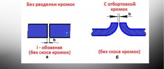
6.5. When preparing butt joints of pipes for welding, it is necessary to check their compliance with the drawings and the requirements of regulatory and technical documentation. Pay attention to the perpendicularity of the cutting plane to the pipe axis (Fig. 2). The deviation of the cutting plane from the square “L” should not exceed the values indicated in the table. 4.
You should also check:
compliance of the shape, size and quality of edge preparation (including boring for a backing ring or for a given internal diameter, as well as cutting for corner and T-joints) with the requirements (processing of chamfers for welding and the dimensions of the edges should be checked with special templates);
quality of cleaning of the outer and inner surfaces of pipe ends (nozzles, fittings), as well as their surfaces in places of corner and T-joints;
correct execution of transitions from one section to another (at the ends of pipes, pipes and fittings subject to welding with elements of other standard sizes);
compliance with the minimum actual wall thickness of pipe ends prepared for welding (nozzles, parts, fittings) established by the tolerance (after boring for a backing ring or for a given internal diameter or cleaning the outer and inner surfaces after calibration).
Table 4
| Pipe outer diameter, mm | Up to 63 (inclusive) | 76-125 | 125-219 | 273-529 | More than 529 |
| Permissible plane skew L, mm | 0,5 | 1,5 | 2,5 |
Rice. 2. Checking the perpendicularity of the pipe ends
6.6. When processing pipe ends, the length of the cylindrical bore L for the backing ring (Fig. 3) must be at least 20 mm for pipe wall thicknesses up to 25 mm inclusive, and at least 50 mm for greater thicknesses. The transition from the machined section to the untreated surface of the pipe should be smooth with a cutter exit angle of no more than 15 º. Boring may not be carried out if the internal diameters of the pipes being joined differ by no more than 2 mm.
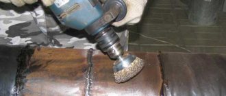
6.7. Processing of the ends (cutting pipes and chamfering) must be done mechanically using special pipe cutting machines. The surface roughness of the pipe edges must correspond to the data shown in Fig. 3. It is allowed to process the ends of pipes with gas cutting, but with subsequent cleaning of the edges with a cutting or abrasive tool until traces of fire cutting are removed.
6.8. Oxygen cutting of pipes made of chrome-molybdenum and chrome-molybdenum-vanadium steels with a wall thickness of more than 12 mm at an ambient temperature below 0 ºС must be carried out with preliminary heating up to 200 ºС and slow cooling under a layer of asbestos.
Rice. 3. Roughness of edge surfaces
6.9. If the difference in internal diameters of the pipes being joined exceeds the permissible limit (clause 6.18), then one of the following methods can be used to ensure a transition at the junction:
a) distribution (idle or with heating) of the end of the pipe with a smaller internal diameter by calibrating it (Fig. 4a).
The scope of application of the method and the permissible distribution value are given in table. 5. After distribution, it is necessary to check whether the pipe wall has become thinner than the permissible size;
b) mechanical processing (boring) on the inner surface of the end of the pipe with a smaller diameter in accordance with Fig. 4b (for a joint without a backing ring) or Fig. 4c (for a joint with the remaining backing ring), provided that the pipe wall thickness after boring will not be less than the calculated one. This method can be used for pipes made of any steel. The cutter exit angle should be no more than 15º.
Table 5
| Steel | Distribution method* | Pipe diameter, mm, no more | Pipe wall thickness, mm, no more | Distribution ** A, %, no more |
| Carbon | Cold | |||
| 84-200 | ||||
| Heated | ||||
| Low alloy: | ||||
| heat resistant | Cold | |||
| Heated | ||||
| structural | Cold | |||
| Heated |
* Distribution with heating should be carried out at a temperature of 900-1000 ºС for the ends of pipes made of low-alloy heat-resistant steels, at 700-900 ºС for low-alloy structural and carbon steels.
** Calculated using the formula A = (D2 – D1) 100 / D1, where D1 and D2 are the internal diameter of the pipe before and after distribution, respectively.
6.10. When joining pipes with different outer diameters, the size h (Fig. 5) should be no more than 30% of the thickness of the thinner pipe, but no more than 5 mm. If the difference in outer diameters exceeds this, the end of the pipe with the larger outer diameter must be machined (see Fig. 5).
Rice. 4. Methods for processing pipe ends when joining elements with different internal diameters
Rice. 5. Processing of pipe ends when joining elements with different outer diameters
6.11. Dents at the ends of pipes can be corrected using expanding devices, provided that the depth of the dents does not exceed 3.5% of the pipe diameter and the wall thickness is not more than 20 mm. Dents on pipes can be fixed by drying or heating.
The ends of pipes with dents with a depth of more than 3.5%, as well as with nicks with a depth of more than 5 mm, should be cut off or corrected by surfacing.
6.12. It is allowed to bend pipes under installation conditions on pipes made of low-carbon and low-alloy structural steels at an angle of no more than 15 ºС, and on pipes made of chrome-molybdenum steels - no more than 10 ºС.
Pipes made of heat-resistant steel, regardless of the wall thickness, when bending, should be heated at the bending point to a temperature of 710-740 ºС. Pipes made of low-carbon and low-alloy steels can be bent in a cold state with a wall thickness of up to 20 mm; for greater thickness - heated to 650-680 ºС. After bending, the heated area must be wrapped in asbestos to slowly cool the metal. The bending point must be located outside the bend of the pipe and, with a diameter of more than 100 mm, be at least 200 mm away from it. The heating temperature is controlled using thermal pencils, thermal paints or thermocouples, and the TTTs-1 device (Vatra). Heat treatment of the hem area is not required.
6.13. The edges of cast pipeline parts must be prepared only in the factory.
Assembling pipe joints
6.14. To secure pipe joints in a position fixed for welding, centering devices should be used and tacks should be installed.
Pipe welding centralizers models TsT-60, TsT-114, TsT-426, manufactured by Poltavsky, can be used as centering devices (recommended Appendix 7, Fig. 1-3). Pipes with a diameter of up to 50 mm can be assembled using pliers (Appendix 7, Fig. 4), and pipes with a diameter of 133-377 mm - using a clamp-type device (Appendix 7, Fig. 5). The assembly of pipes with a diameter of more than 100 mm can be done using clamping angles or compensation strips (Appendix 7, Fig. 6).
6.15. In the case of assembling a joint of pipes made of chrome-molybdenum steels using angles or compensation strips, welding of these elements to the pipes should be done using electrodes of the E46A or E50A type with preheating of the welding site. Corners and strips can be removed (mechanically or gas cutting) only after applying at least two or three first layers of seam. The places where these parts are welded to the pipes must be cleaned and carefully inspected for detection and removal of surface cracks.
It is recommended to make corners and compensation strips from carbon steel 20, St2, St3.
6.16. The structural dimensions of welded joints in accordance with GOST 16037 are given in the recommended Appendix 8.
6.17. Immediately before assembling the edges, the inner and outer surfaces of the pipes in an area of at least 20 + 20 mm from the ends must be cleaned to a metallic shine and degreased. Before installing the fitting (pipe) into the manifold or drum, the surfaces around the hole must be cleaned 15-20 mm from the side of the weld and the surface of the hole must be cleaned to the full depth.
6.18. The displacement of the internal surfaces of welded pipes (and shaped parts) when welding joints with one-sided cutting of edges without a backing ring should be no more than the values indicated in the table. 6.
For pipes with a diameter of more than 200 mm, the displacement of the inner edges should be no higher: for a tube thickness S up to 4 mm - 0.2S, for a larger thickness - 0.15S, but not more than 2 mm.
Table 6
| mm | |||
| Pipe wall thickness, S | to 10 | Over 10 to 20 | Over 20 |
| Maximum permissible displacement of internal edges | 0,5 | 0.05S |
6.19. For pipe joints assembled and welded on the remaining backing ring, the difference in the internal diameter of the elements at the joint should not exceed 2 mm so that in the assembled joint the gap between the ring and the inner surface of the element is no more than 1 mm.
6.20. The displacement from the outside of the surface of welded pipes and equipment elements with the same wall thickness should not exceed the values specified in table. 7.
Table 7
| Nominal wall thickness of connected elements (parts), S, mm | Maximum permissible displacement (mismatch) of edges in butt joints, mm | ||
| longitudinal, meridional, chordal and circular on all elements, as well as annular when welding bottoms | transverse ring | ||
| for pipe and conical elements | for cylindrical elements made of sheet or wire | ||
| 0-5 | 0.20S | 0.20S | 0.25S |
| >5-10 | 0.10S + 0.5 | 0.10S + 0.5 | 0.25S |
| >10-25 | 0.10S + 0.5 | 0.10S + 0.5 | 0.10S + 0.5 |
| >25-50 | 3 (0.04S + 2.0)* | 0.06S + 1.5 | 0.06S + 1.5 |
* May only be permitted in cases specified in the working drawings. In butt welded joints made by electric arc welding on both sides, the specified edge displacement should not be exceeded on either the outer or inner sides of the seam.
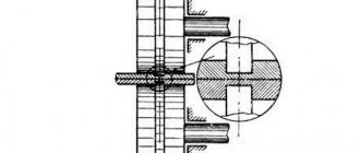
6.21. The straightness of the pipes at the joint (no fractures) and the displacement of the edges are checked with a 400 mm long ruler applied in three to four places around the circumference of the joint (Fig. 6).
The maximum permissible clearance “a” between the end of the ruler and the surface of the pipe in an assembled (but not welded) joint should not exceed 1.5 mm at a distance of 200 mm from the joint. In a welded joint it should be no more than 3 mm.
Rice. 6. Checking the correct assembly of the butt joint
6.22. The location of transverse welds on pipes (Fig. 7) must meet the following requirements:
Distance between the axes of adjacent transverse seams l1, at S, mm
| up to 8 | at least 50 |
| more than 8 | not less than 3S, but not less than 100 |
Distance from the beginning of the bend (rounding) to the axis of the transverse seam l2, from the outer surface of the element (drum, chamber, transit pipe) to the axis of the transverse seam l3 or to the beginning of the bend l4 at Dn, mm:
| up to 100 | not less than Days, but not less than 50 |
| more than 100 | not less, but not less than 100 |
Rice. 7. Location of transverse welds
6.23. When assembling pipes and other elements that have longitudinal or spiral seams, subsequent ones must be offset from one another.
The displacement (for pipes Ø > 100 mm) must be at least three times the wall thickness of the pipes (elements) being welded, but not less than 100 mm.
Welding the backing ring
6.24. When assembling pipeline joints with backing rings, there should be no distortion of the backing ring. Tacking and welding of the backing ring is carried out by a welder who will subsequently weld this joint, or by a welder who has a certificate for the right to weld such joints. The sequence of assembling the joint with the backing ring should be as follows:
the backing ring should be installed in one of the pipes with a gap between the ring and the inner surface of the pipe of no more than 1 mm;
tack the ring from the outside in two places and then weld it to the pipe using a thread seam with a leg no more than 4 mm (Fig. 8a). Tack welding and welding of a ring to a low-alloy steel pipe should be performed with preheating of the end of the pipe and the backing ring in accordance with the data in Table. 9;
clean the thread seam from slag and splashes;
slide the second pipe to be joined onto the protruding part of the backing ring (the gap between the end of the thread seam and the second pipe should be 4-5 mm), check that the joint is assembled correctly;
Weld the backing ring with a thread seam to the second pipe (Fig. 8b);
preheat the joint in accordance with the requirements of the table. 9.
The root layer should be welded with electrodes with a diameter of 2.5-3 mm.
During the assembly process, pipes with a welded ring should not move or be subject to impacts on the edges and the ring.
Rice. 8. Welding the backing ring a – to the first pipe; b – to the second pipe
6.25. Backing rings for joints of pipes made of low-carbon and low-alloy steels should be made of steel 20 or other low-carbon steel of mild or semi-mild smelting with a carbon content of no more than 0.24%; For joints of pipes made of low-alloy heat-resistant steels, backing rings made of steel 12Х1МФ can be used. Dimensions of the backing ring: width – 20-25 mm, thickness – 3-4 mm. If the ring is made of strip steel, the butt seam of the ring should be cleaned flush.
Previous3Next
Conflicts in family life. How can I change this? It is rare that a marriage and relationship exists without conflict and tension. Everyone goes through this...
What will happen to the Earth if its axis shifts by 6666 km? What will happen to the Earth? - I asked myself...
What makes your dreams come true? One hundred percent, unshakable confidence in your...
What Causes Trends in Stock and Commodity Markets Freight Train Theory Explained My first 17 years of market research consisted of trying to figure out when...
Didn't find what you were looking for? Use Google search on the site:
How to choose electrodes for proper pipe welding
Before you start welding heating pipes or any other pipes, you need to stock up on electrodes. Their quality directly affects the reliability of the resulting connection, the tightness of the structure, as well as the welding process itself.
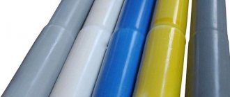
Electrodes are a thin steel rod with a special coating that provides a stable arc during operation and forms a weld that prevents oxidation of the metal.
VT-metall offers services:
Electrodes are qualified by the type of core and outer coating.
Depending on the type of core, electrodes are divided into:
- consumables with a non-melting center made of graphite, electrical coal or tungsten;
- with a melting center - wire, the thickness of which varies depending on the type of work performed.
Based on the type of external coating, electrodes are divided into the following groups:
- With cellulose coating (grade C). Designed for proper welding of large diameter pipes; they are used to install gas and water mains.
- With rutile acid coating (RA). Used to work with metal heating or drainage pipes. The resulting weld is covered with a small layer of slag, which is removed by tapping.
- Rutile coated (RR). Allows you to obtain neat welding seams with slag that can be easily removed from the surface. These electrodes are used for corner joints, as well as when welding the second or third layers of metal.
- With rutile cellulose (RC) coating. They can be used for correct welding of pipes in any planes, for example, when creating a long vertical seam.
- With base coat (B). These are universal consumables suitable for working with thick-walled pipes and parts intended for use at sub-zero temperatures. Allows you to obtain a high-quality plastic seam that is not subject to cracking or deformation.
Before starting welding work, it is worth obtaining advice from welding specialists regarding their preferred brands of electrodes. At the same time, there can be quite a lot of recommendations, and consumables may vary depending on the store or city.
We recommend articles on metalworking
- Steel grades: classification and interpretation
- Aluminum grades and areas of their application
- Defects in metal products: causes and search methods
There is a direct connection between the cost and quality of consumables. With cheap electrodes it is difficult to weld pipes correctly and obtain a high-quality weld. Therefore, there is no need to save on these consumables.
Methods for proper pipe welding
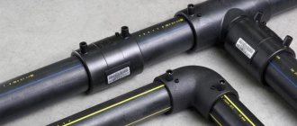
There are various methods for properly welding polypropylene pipes and products made from other materials using the electric arc method:
- end-to-end - in this case the pipeline elements are located opposite each other;
- in a T-bar - in this case, the pipe sections are located perpendicular to each other (in the shape of the letter “T”);
- overlap - this method involves flaring one of the pipes, allowing it to be put on the other;
- angular method, in which the elements are placed at an angle of 45° or 90° relative to each other.
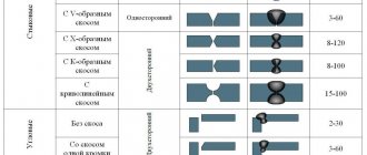
In the process of proper pipe welding, the following types of seams are obtained:
- horizontal (with a vertical arrangement of pipeline elements);
- vertical (if the pipes are located vertically);
- ceiling (with the electrode placed above the welder’s head, in the lower part of the workpiece);
- lower ones (you have to bend over to do this).
If it is necessary to connect steel pipes, the butt method is used. In addition, the joint must be welded to the thickness of the workpiece wall. A bottom turning seam is best for this.
To obtain a high-quality welded joint during the work process, you should adhere to the following recommendations:
- During welding, the electrode should be positioned at an angle of 45° or slightly less. This will reduce the amount of molten metal entering the pipeline element being welded.
- For T-welding or butt welding, 2-3 mm electrodes will be required. A high-quality welded joint will be obtained with a current varying from 80 to 110 amperes.
- To get a reliable overlap connection, you will need to increase the current to 120 amperes; 2-3 mm consumables (electrodes) are also suitable.
- The weld seam should rise 3 mm below the surface of the workpiece being welded, after which we can talk about completing the work.
Correct welding of profile pipes is carried out spot-welding, that is, first two points located on opposite sides of the profile are welded, then two other points, continuing work until the entire pipe is heated. Next, a welding seam is formed along the entire perimeter of the workpiece.
Selecting Electrodes
For welding steel pipes using the electric arc method, the diameter of the electrodes is selected according to the thickness of the mounted rolled product. It is important to take into account the characteristics of the electrode rod and coating. Features of electrodes used for pipeline installation:
- Electrodes MR-3, ANO-21, ANO-24 are used to weld seams that do not experience high pressure (drainage systems, waste pipelines), where the flow rate is insignificant. Can work on alternating current.
- Universal SSSIs are recommended for use by beginners; they weld metal well and form a strong connection. For large volumes of electric arc welding, they are not effective due to the low speed of seam formation and the need for constant control of the arc.
- LB-52U - electrodes from Japanese manufacturers are used for installation of process and main pipelines designed for high pressure. The LB-52U is characterized by smooth combustion even with a slight “sag” in the voltage in the network.
- Electrodes from the Swiss company ESAB are distinguished by good seam quality; manual arc welding of high-pressure gas lines is often carried out by them. OZS 12 is used for low-carbon steels, OK 46 is universal. OK 53.70 and OK 74.70 are cooked on a current of any polarity; the coating contains a protective flux that inhibits oxidation of the melt pool.
- Domestic LEZ LBgp is used for the finishing layer on butt joints of thick-walled pipes and for welding thin-walled pipes.
- E42A, UONII-13/45, E-09H1MF are used for the installation of heating systems made of alloy steels; thick coating of type D forms a slag layer that protects the molten metal from oxidation.
The trouble-free operation of pipeline networks largely depends on the electrodes. The steel of the rod must correspond to the grade of rolled steel; the type of coating determines the degree of protection of the melt pools.
When choosing a method for installing a process pipeline or utility networks, take into account the thickness of the rolled product, steel grade, and working load on the metal. Thick walls are welded using multi-layer seams with preliminary cutting of the edges. It is enough to clean thin-walled rolled products before carrying out work. Having a welding machine, you can weld the joints yourself.
Preliminary work for proper pipe welding
Before you begin to properly weld plastic and metal round pipes, you need to pre-process the joints and clarify a number of nuances. First of all, they diagnose the pipe’s compliance with certain technical characteristics that apply to the installed system, in particular to the water supply system.
Necessary:
- observe geometric dimensions;
- have a quality certificate, especially if a pipeline for drinking water supply is to be installed;
- so that the pipe is perfectly round in shape, since defects, a flattened or oval section of the workpiece are not acceptable;
- control the wall thickness along the entire length of the pipe - it should be the same;
- The chemical composition of the part must comply with the requirements of GOST - this information is contained in the technical documentation or is determined in the process of laboratory research.
After this, you can begin preparing the pipes for joining and welding.
During the preparation process, you must complete the following steps:
- check the evenness of the cut at the end of the pipe, it should be 90°;
- thoroughly clean the end of the workpiece to be welded and the 10 mm area around it until a metallic sheen appears;
- remove residual oils, rust, paintwork from the surface of the pipe, degrease the ends of the element.
In addition, you should ensure that the end has the correct configuration. The opening angle of the edge should be 65°, the dullness index should be 2 mm. The required parameters can be obtained through additional processing.
Correct pipe welding: step-by-step algorithm
In electric welding, a strong connection between workpieces is achieved through a thermal process. In this case, the quality of the seam will be higher than with gas welding.
If the pipes are located in an accessible place and can be rotated, then it is necessary to connect the two pipeline elements end-to-end with one or three electric welding points, and then continue welding the workpieces:
- continuously (if it is possible to rotate the parts);
- with a separation, starting from the bottom, if the pipe is located inconveniently and there is no way to rotate it.
Welding work is performed in two approaches. Initially, the first seam (“root”) is made, covering 2-3 mm of the joint of the workpieces, after which the resulting deposits and scale are removed. Then a second seam is formed, which is also cleaned.
The algorithm for proper pipe welding is as follows:
- Before you start working directly, you need to take a stable position and take care of good lighting of the space.
- Light the arc, increasing the current if necessary.
- Place the electrode at the beginning of the weld, form a weld pool, maintaining a constant arc gap.
- A sufficiently large current will cause particles of straightened metal to follow the heat.
Movements must be adjusted and careful, since too much current will cause the metal to melt too much, begin to bubble, and it will not be possible to form a weld. - In the process of properly welding pipes, it is necessary to ensure that the edges are filled and that there are no undercuts.
If the current is low, then the weld pool will be equal to the outline of the electrode. By increasing the current, moving the electrode in a circle or from side to side, you can form the correct welding seam. Attention should be paid to the quality of welding during the processing of workpieces, ensuring the uniform filling of the weld pool. - Place a point, leaving a small amount of metal.
- Extinguish the arc along the seam.
Over time, you can learn how to properly weld pipes and form high-quality seams, but it will be easier for those who previously observed the work from the outside or were a welder’s assistant.
Common Mistakes
Very often, correction of defects and modification of welding joints is caused by inaccurate preparation of the seam. To get good welding results, avoid these common mistakes:
- Very often you can find beveled edges with an angle that is too sharp, which leads to poor penetration of the weld seam into the depth of the weld joint.
- Not good enough to remove oil, dirt, paint or varnish from the base metal. Improper cleaning methods can cause the grout to become porous. Using grinders is the fastest way to clean the welding area. Make sure you clear at least 2-5cm from the end of the piece to prevent foreign material from getting into the seam.
- Not following welding procedures may seem like a good way to save time and increase productivity, but it can also lead to further rework, corrections, and failed welds. Before welding pipes, you should familiarize yourself with the specifications and technological processes, they usually contain the correct bevel angle, gap size, weld root size and other important details.
Safety precautions when welding pipes
During electrical work, including pipe welding, it is necessary to comply with safety requirements. Their violation can result in various injuries, for example, thermal burn of the skin or retina due to an arc flash, electric shock, etc.
To avoid trouble, you should pay attention to the following before starting work:
- electrical wires and parts of the welding machine must be insulated;
- the body of the welding equipment and additional devices must be grounded;
- You can only wear completely dry overalls and gloves;
- for additional insulation it is necessary to use galoshes or a rubber mat (for a small room);
- Be sure to protect your eyes and face by wearing a protective shield.
By following the information presented in the article, you can independently learn how to properly weld pipes using electrical equipment. However, it is impossible to achieve success without practical skills. Using our recommendations, you can start practicing welding and over time get decent results in welding metal pipelines.