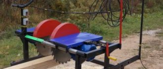
Types of planing machines
The design of the clamping mechanism directly depends on the equipment model. Therefore, it is first necessary to carefully study the technical documentation, the features of the machine elements, and their characteristics.
The most common option is a power unit (electric motor) that drives a cylindrical cutter head. Its upper part is located above the level of the support table. The latter can move relative to the cutting part in the vertical direction. In this way, the depth of processing of the wooden workpiece is adjusted. You can make a similar model with your own hands.
In addition to the woodworking machine described above, the following types of equipment are used for mass production:
- thicknesser with one cutting head;
- cycle. Installed on lines for assembling furniture, door and window structures;
- two, three and tetrahedral. Processing occurs in several planes at once, which increases productivity;
- models with several knives.
Almost all modern equipment has clamps. The exceptions are machines made by yourself or old models.
When choosing a retainer design, you should pay attention to the equipment configuration. After its installation, the operational and technical qualities should not deteriorate.
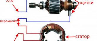
Types of clamping devices for a milling machine
High-quality machining of parts directly depends on the performance characteristics of the clamp. When drilling or boring metal elements, a vice is used. Instead, it is very convenient to use special fastening components - clamping strips with a thrust screw.
On the modern market of building materials and tools you can find a large number of fasteners and sets of clamps for milling machines and other units:
Used for low-profile clamping of workpieces on the milling machine table
- clamps: universal, stepped, curved, fork-shaped, movable;
- supports and struts;
- corners;
- stops;
- fastening kits for various numbers of elements;
- sets of plates and angles.
The fastening set is used in cases where the machine vice is unable to grip a complex structure. The set contains additional fastening devices that allow you to grip: studs, supports, angles, nuts of different lengths, clamps with a corrugated surface.
A set of plates and squares is used if it is necessary to fine-tune and secure an object on the working surface of the machine.
Universal unlined clamp
If it is necessary to secure a part on the machine table, use a clamping bar and supplement it with a support. A screw stop or a lining is used as a support. The design ensures quick and reliable fastening of material on the table of a milling machine and other processing machines. The device looks like this: T-bolt, stand, strip, locking washer.
First, the clamping mechanism is assembled, then it is installed on the frame of the processing machine and brought to the working element. The screw rests against the bar, the body is turned around its axis and secured.
C-shaped clamp
The device does not have a lining; using a hinged joint, the mechanism can be installed at the required height. To quickly adjust the height of the device, the fixing nut is made of two halves, onto which a special ring is placed. If necessary, the ring is removed, the nut is set to the desired height, and the ring is put on. The nut rotates and moves along the threads of the bolt, thereby securing the structure.
Quick release clamp
Designed to secure the part on the bed of a processing machine. The basis of the design is a lever-spring mechanism. The package includes:
Scheme of operation of the high-speed clamp
- rack;
- toothed strip;
- spring;
- clamp body.
In the upper part of the clamping device there is a spring, under it there is a gear rack with a handle. This simple mechanism quickly fixes the body of the clamping unit, allowing it to move along the entire height of the rack.
This design helps reduce setup time and subsequent operations with the element being processed on the machine.
Comb clamping mechanism
Has a durable plastic housing, used for milling machines and circular saws. Each tooth of the comb clamp has a precise shape, which ensures a tight and optimal clamping of the part. The fastening system allows you to combine fasteners with any equipment without additional devices.
The composite teeth of the clamping unit are positioned at a slight angle, which creates pressure on the workpiece from above and on the sides, without leaving any damage to the workpiece during operations on the machine.
Using a clamp
So that when processing the workpiece, the chips are carefully removed and the edge of the cutting tool is visible, the material being processed is placed at a distance of 2.5 centimeters from the edge of the milling table. The result is achieved by adding lining material, each element of which has the same thickness.
Clamp
A clamp is a cylindrical object, inside of which a clamping device and a pin are placed. A spring presses on the device from the bottom, which helps to hold the structure in the upper position.
On the body of the clamp, side slots are visible, which serve as places for attaching the object to be processed. The device allows you to securely fasten parts with a thickness of no more than 3 centimeters.
A clamp is an auxiliary tool with which spare parts are secured to a milling machine and other machines for further processing. With little effort, the clamp creates the necessary force to securely fasten the part. There are several types of clamps that provide clamping of the product:
- F-shaped - work with large-sized parts;
- G-shaped ones are used when it is necessary to secure a small object. This is the most common type of clamp, made of cast metal or cast iron;
- the pipe type is designed to exert significant pressure on the components being processed;
- The corner clamp is capable of connecting parts at an angle.
Purpose of the clamping device for the machine
At first glance, modification of the woodworking machine is necessary only to fix the workpiece. However, with the correct choice of manufacturing scheme, the installed part can perform a number of other, no less important functions.
When processing wooden products, you can adjust their fixation manually. Ultimately, this affects the quality of the surface. This is especially true for thin strips, the thickness of which does not exceed 2-3 cm. Therefore, a do-it-yourself fixing device, after installation on the machine, should have the following functions:
- smooth adjustment of the fixation level. It is carried out by uniform pressure on the part;
- the quality of processing should not depend on the length of the product;
- during operation, the equipment elements do not damage the wooden surface;
- safety. The operational qualities of the mechanism must meet modern occupational safety requirements.
Before starting design, it is recommended to familiarize yourself with similar factory models. To make the clamping mechanism with your own hands, scrap materials will be used. Therefore, when choosing the optimal design, it is necessary to be guided by the principle of expediency.
Experts do not recommend installing a fixing device for a jointer. This may affect the quality of the products.
Review and comparison of factory models
| Model | UP-2000 | UP-05 | UP-2200 | UP-2500 |
| Processing width, mm | 230 | 200 | 250 | 270 |
| Workpiece thickness, mm | 8-63 | 8-63 | 8-63 | 8-63 |
| Weight, kg | 3 | 2,5 | 3,2 | 5,6 |
| Dimensions, mm | 293*304*113 | 255x270x105 | 293*324*113 | 293*344*113 |
| Price, rub | 2871 | 2871 | 3133 | 3393 |
UP-2000
UP-05
UP-2200
UP-2500
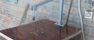
Homemade clamp: option No. 1
Most often, for the manufacture of the above-described design, a part from an old washing machine is taken as a basis, and in particular, rollers for squeezing out moisture. In some cases, after minor modifications, the add-on can be installed on the equipment.
The frame consists of four support legs, which are connected to each other by a U-shaped profile. Locking shafts are installed on it. The profiles are not fixed to the base, but move freely along them. At the top of the structure there is a locking bar connected to the adjustment handle by a worm gear. For shock absorption, you can install springs that will partially compensate for the strong pressure when processing uneven surfaces.
The structure consists of the following components.
- Screw.
- Connection plate.
- Plate providing reliable fixation.
- Support stand. To complete the set you will need 4 pieces.
- Two rollers.
- Two side supports for rollers.
- Compensation springs - 2 pcs.
- Screw.
- Fixing axes for rollers.
Using the top handle, you can adjust the degree of pressure. The disadvantage of this model is its large massiveness. It may not be suitable for all types of machines.
To reduce the labor intensity of manufacturing a mechanism for a planer, you can use the rollers of a washing machine. They need to be trimmed first.
Clamp with automatic fixation: how to make
The benefits of such a tool as a clamp are known to all craftsmen. An irreplaceable item for carpentry and plumbing work. Clamps are also often used by welders, builders, car mechanics and home craftsmen. There are many designs and sizes of clamps, but basically they are all similar in that they must be tightened by hand - tighten the tightening screw, after which the objects on which the clamp is installed are securely fixed. It should be noted that this is a tedious task, tightening and unscrewing each time a clamp screw to fix or release an object. On the Internet I found a version of a clamp with automatic fixation. Such a clamp does not need to be tightened by hand on the object being fixed. One click on the upper movable stop of the clamp is enough and the object will be securely pulled to the edge of the workbench, for example, a wooden block.
It will also not be difficult to release the block; to do this, you need to press the upper stop again and the “grip” of the clamp will immediately weaken, the block will be freed from the clamp.
How to make such a clamp?
It's not difficult to do. You will need a metal strip and a size 20 profile pipe.
The clamp consists of two stops, a lower fixed one and an upper movable one.
Bottom stop
We vertically weld a profile pipe to a piece of metal strip from one edge. We weld an overlay made from an old flat file onto the strip. This completes the manufacture of the bottom stop.
Upper stop
Making it will be a little more difficult. Cut a strip of the same length as that at the bottom stop. Using a mini drill, we cut a square hole from one edge of the strip section. The size of the hole should be slightly larger than the size of the profile pipe along which this segment (upper stop) will move.
The piece with the square slot must be clamped in a vice and bent slightly from the side of the square hole. This is the design feature of the clamp, thanks to which the upper movable stop is fixed on the vertical profile pipe.
Next, according to the size of the overlay (an overlay from an old file welded to the lower stop), we cut off a plate and another overlay from a file (for the upper stop).
We weld the plate crosswise to a section with a square hole, and drill regular round holes for bolts along the edges of the plate.
We apply the file plate to the plate with round holes. We make marks on the plate along the holes of the plate.
We weld the bolts to the marks (the caps of the bolts should be cut off so that only the thread remains).
The upper support blanks are made, we connect them together. We install springs on the welded bolts, insert the bolts into the holes of the plate, and screw on the wing nuts.
The top stop is assembled.
We connect the lower and upper stops - insert the profile pipe into the square hole of the top stop.
The homemade product is ready to use!
How to use is described at the beginning of the article. This is what the emphasis looks like on a clamped block. It holds quite tightly, you can't loosen it with your hands.
The springs press the upper plate with a square hole from one edge, the plate becomes skewed and locks on a vertical profile pipe. When pressed again, the plate becomes straight and can again be moved along the pipe.
Homemade clamp: option No. 2
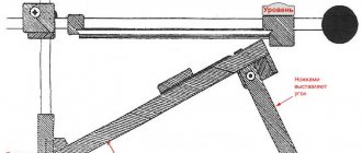
An alternative option for making a machine clamp with your own hands is a slight modification of the equipment. It consists of installing two slats on the sides of the frame. Two bearings are installed in the main working shaft, through which a fixing axis passes.
Read also: Weaving keychains from rubber bands for beginners
The difficulty may lie in the configuration of the bed. All models have smooth edges to allow mounting of eyelets. The degree of clamping is adjusted using a spring. It moves along the slats, thereby changing the pressure on the workpiece.
- Main working shaft.
- Bearings.
- Threaded axle.
- Screw.
- Plates.
- Traction.
- Springs.
- Fixation for springs.
- Ellipse axis.
- Two plates.
- Stopper.
- Ellipse.
- Lever.
- Axis.
- Two eyes.
- Corner.
- Bolt for fastening.
The advantage of this system is an increase in labor productivity. When feeding a workpiece, its end part will rest against the shaft, lifting it. This will allow you to process several parts without first adjusting the homemade clamp.
The video shows an example of another design of a locking mechanism:
Need a photo or drawing of the design of clamping the workpiece on a jointing machine
Or maybe try to use the principle of spinning clothes in old “Soviet” washing machines. Remember, there were two rollers and they were turned with a handle.
So I intend to use the parts from this unit, namely the roller itself, and I need to think about the design of the clamp, together with the forum.
Or maybe try to use the principle of spinning clothes in old “Soviet” washing machines. Remember, there were two rollers and they were turned with a handle. __________________
What kind of jointer do you have?
Yes, an ordinary homemade jointer with three knives. What's the difference?
This is even better. Because it’s more difficult to attach to a factory structure! Do you already have any thoughts?
Yes, I have thoughts, but somehow I can’t put them in one pile, maybe I’ll start doing it on Monday, I’ll try to take a photo of what happened
Can you clarify whether it is a manual jointer or a jointer? If it’s a machine, I don’t recommend using a clamp if you want to get a flat surface. I know from my own experience that when I started working on a jointing machine I tried to press the workpiece harder against the tables and remove more per pass, I thought I needed to “drive” less, and after the surface planer you’ll see whether there’s a hump or a hole. Then I set it at 1-1.5 mm, you don’t put pressure on the workpiece, but just hold it so that it doesn’t “walk.” After the surface planer, everything is even and smooth, it’s especially good if there are 3 knives on the shaft, the workpiece jumps less.
[email protected] wrote: press the workpiece harder against the tables and remove more per pass, I thought it was necessary to “drive” less, and after the surface planer you’ll see if there’s a hump or a hole. Then I set it at 1-1.5 mm, you don’t press on the workpiece, but just hold it so that the smooth thing doesn’t “walk”, wasps. After the surface planer, everything is a sight for sore eyes Complain about this message
Yes, it’s not a matter of effort, let’s say the planes of the workpiece on both sides are convex (in the shape of an ellipse). Well, how can you smoothly plane it with a clamp? And then I lifted it a little with my hand and then pressed it a little, and it looked like it would be flat.
If you want to get a smooth surface when jointing, completely forget about any clamps, they only cause harm, zero benefit. Please note that any board is a spring: if, when jointing, you even slightly press it against the surface of the table and release it after jointing (i.e., remove the vertical load), the board will take on its original shape (i.e., the original curvature), but it will only become thinner by the amount of material removed during gouging. This way it can be “leveled” to the thickness of a newspaper sheet. To obtain a perfectly flat surface of the board, two other points are important: - very sharp knives (in one of the workshops where I worked, the knives on the jointer were changed at least once a day - there was a lot of oak, beech and birch); - the most accurate alignment of the cutting knives along the receiving surface of the jointer - no higher and no lower. All the rest . from the evil one. You should always start jointing with the belly facing up - level the bottom side, the belly is removed in the surface planer. A “belly” on both sides = a terrible rarity, but in this case too – bigger up.
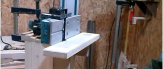
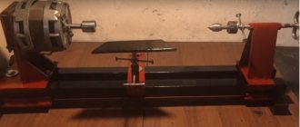
Wood planing is an indispensable stage of woodworking. Planing can be done either with a hand plane or with an electric one, but for more professional work, a planer is better suited. An industrial design costs a lot of money, so here we will try to figure out how to make a jointing machine with our own hands, using a household electric hammer.
Read also: Cold welding metal and plastic
How to assemble a planer-thicknesser machine with your own hands?
When processing wooden sources, many are faced with the task of obtaining parts of the same size. This problem is solved by using a thickness planer. Such machines belong to planing equipment. But they still have a pressing and feeding mechanism, and these installations are capable of processing several workpieces.
Classification
There are different types of these installations depending on various factors. By type of drive there are:
- Manual drive machines.
- Electrically driven machines.
Most of these machines come with an electric motor to make work easier. For household varieties, the motor is designed for 220 V, and for professional equipment - 380 V.
Depending on the feed, the installations have one or two pairs of feed rollers. If there is one pair, then the clamping of the workpiece must be very strong. In this case, vibration phenomena may occur during pruning. Machines with two pairs of feed rollers are considered the most convenient and adaptable.
The number of knife shafts contributes to the division into:
- Single-sided - have an upper blade shaft.
- Double-sided - in addition to the upper knife element, there is another one in the working area, which receives the workpiece first.
According to the functions they perform, thicknessing machines can be used not only for processing the workpiece, but also for the subsequent calibration process. In this case, the occurrence of diametrical chips and other defects on the workpiece is eliminated.
Based on the technical properties, the installations are divided into machines of different power, shaft speed, planing width and thickness of the initial element. Separation is also possible depending on the speed of the process.
There are models with different methods of adjusting clearances and the design of the main drive bearing module.
Based on the type of planing, there are two categories of equipment:
- Slitting machines.
- Cross cutting machines.
Machine operating rules
A planer-thicknesser machine involves obtaining a smooth surface of a wooden part, and further calibration to the desired size. Machine tools used for domestic needs are composed mainly of the following components:
- main cutting part (knife shaft);
- working surface;
- engine;
- rollers.
The working surface is formed by two parts: supply and receiving. The knife shaft is located between these two parts, providing cutting. The rollers perform the task of supporting the workpiece for smoother and safer cutting.
The front roller is grooved for better grip on the wood base. And the rear roller has a flat base. Models with double-sided feed have an additional unit for extending the knife shaft. In this situation, replacing tools to change sizes is greatly simplified.
The operation of the machine begins with the transmission of a signal from the engine to the knife shaft. The workpiece is fed first to the lower rollers, and then to the upper ones. Next, the tool starts cutting. When the workpiece leaves the rear guide roller, another part enters the front one. And so, cyclically, the processing process goes on.
Many people are thinking about buying a thickness planer. If you have, for example, a planer and planer, then why use a thickness planer? The planing machine only levels the surface of the board, and the surface planer makes the board uniform over the entire area. Thus, if you combine both machines in one, you can obtain the correct parts for the precise production of furniture or even slats for sheathing.
There are many models of planer-thicknesser machines on the market. Recently, the number of Chinese models that are considered unreliable has increased. Moreover, much of the equipment sold is large and may not fit in a barn or other utility room. Then there is a way out - to do such an installation yourself.
First of all, you should purchase the main parts and assemblies in the store, since hand-made elements may differ in the correct pairing, which will lead to overheating under heavy load. Your own installation requires the presence of both a jointer and a surface planer. On the one hand, the part will be planed, and on the other, the process of bringing it to the required parameters will be carried out.
It is also worth initially choosing the size of the knife shaft. The diameter and fit dimensions must correspond to the production of plinths or other decorative parts on the machine. When choosing a long shaft length, waves may form on the surface of the workpiece due to loss of rigidity when working with a solid base.
The installation of the machine should be based on safe working conditions. The working surface of the bed must be designed in such a way as to exclude the possibility of reverse movement of the workpiece. You should also protect yourself from destruction of the board during processing.
One of the conventional planing machines is known to be equipped with a table made of sheet metal with a hole for the cutter shaft. For such an installation, it is possible to regulate the thickness of the removed layer. Depending on the length of the workpiece and the force of pressing it against the table, the process of moving the board towards the knife shaft begins, and the removed layer becomes larger.
As a result, the workpiece is not in a horizontal position, but at a certain angle to the tabletop, which distorts the accuracy of processing. If, of course, the table has a long tabletop, and the layer being removed is very small, then such a drawback will be invisible, but it still exists. Because of this, a thickness planer is not made from the planing equipment described.
The most suitable for do-it-yourself remodeling would be a machine with a table that has 2 parts of the table top. The tabletop parts are located at different levels, eliminating interdependence. The back part is located in the position of the top point of the circle, which is obtained by rotating the knife part.
The lower part helps to obtain the required thickness of the removed layer. Thus, the workpiece moves in a translational mode, and the disadvantage described above is not observed.
To adjust the level of the table parts ratio, you should use spacer material or an adjusting bolt. It is very convenient to make adjustments using wedge guides.
In order to use this machine as a thickness planer, a clamping and bearing mechanism must be placed on this equipment. The clamping part will provide planing. Based on the fact that the clamping mechanism is much more stable than the load-bearing one, the completeness of the layer being removed will be a predominant factor regarding calibration.
If you need to make a smaller workpiece, then the frame of the pressure element roller will rest against the limiter. As a result, the supporting mechanism will begin to work. The presence of a limiter in the supporting mechanism is intended for the frame roller when raised to a height, which prevents it from coming into contact with the edges of the window in the near area of the table.
It is better to work together on this homemade thicknessing machine. One operator will supply the wood, and the second will remove the boards from the device.
Video: how to make a surface planer from a household planer?
Mounting accessories
When making a machine with your own hands, here are some tips to improve installation:
- It is best to use tubular steel with a diametrical cut of 0.6 * 0.4 cm as the material of the frame. Due to its good rigidity and moment of resistance, such a pipe will increase the processing accuracy.
- The structure is assembled by welding, but it is possible to use assembly using corners and connecting pins. In this case, you need to check the tightening at the points of attachment to the frame more often.
- Rollers from a washing machine can be used as feed rollers. In this case, the rollers are made to fit the size of the existing bearings, observing the required adjustment range.
- When making a table, it is better to use a large-area sanded board made of durable trees (oak, larch). Material impregnated with fire-resistant solutions or creosote will have increased anti-corrosion properties and fire resistance.
- The motor power must be suitable for the processing purpose. Motors with a power of 5-6 kW and a speed of 3500-4000 rpm. will be acceptable for the household.
- The presence of a removable casing will increase safety during operation.
After purchasing all the components, you can assemble the equipment. To do this you need:
- Achieve the most even table area.
- Bring rotating parts into balance in stationary and moving modes.
- Calculate a way to conveniently adjust the position of the table.
- Check the running parts barrier mechanism for reliability.
The installation is checked at idle. During normal operation of all modules, painting of fixed parts occurs.
A do-it-yourself planer-thicknesser installation will allow you to process wood for various purposes. The resulting quality will increase the applicability of the manufactured parts for numerous areas of use in the household.
metmastanki.ru
Various designs of jointing machines
Structurally, jointing equipment manufactured in industrial conditions is very different from machines made independently. They differ in the materials used, technologies, auxiliary equipment, etc. But this does not mean that a homemade jointing machine made from a simple electric planer will not be in demand for home use. It is quite suitable for processing small parts in small quantities.
There are two main types of wood planing machines:
- Single-sided machines (the production of this option will be discussed). With such equipment, only one surface can be processed in one pass. Structurally, these are the simplest devices;
- Double-sided or two-spindle. Such a device can simultaneously process two adjacent surfaces of a part. It is quite difficult to make such equipment yourself.
In addition to the above types, you can also add that machines can be both stationary and mobile.
main idea
Yes, such a homemade jointing machine, unlike serious industrial designs, has a number of disadvantages, namely:
- Cannot boast of high processing accuracy;
- The width of the workpiece is very small - only 110 mm;
- Lightweight is a disadvantage, since a heavy massive base always gives the device stability and, as a result, ease of use, which ultimately improves the quality of the result.
- Low power, limited by the power of a household electric planer;
- The body material is wood, that is, not durable;
However, it also has undeniable advantages that make it very useful for achieving certain goals and performing a number of tasks, since it has the following advantages:
- Low cost - serious jointing machines cost tens and hundreds of thousands of rubles, and the cost of this homemade jointing machine consists of the cost of the plane and materials;
- Compact and portable - it can easily be stored anywhere in the workshop and can be deployed for work in a matter of minutes.
- The simplicity of the design affects its reliability and maintainability.
- The ability to make the necessary dimensions of the machine “to suit you”, for example, you can increase the length of the work table or change the height.
Let's sum it up
In the process of woodworking, in most cases it is impossible to do without a carpentry clamp. Whether it is necessary to glue wooden blanks, secure a sheet, board, or slab during cutting - you will definitely need a clamp. There are similar products on sale, but, according to reviews from experienced craftsmen, they are characterized by two significant drawbacks - size limitations and low strength, since soft metals (alloys) are mainly used for their production in order to reduce costs.
Those who have to work with wood quite often prefer homemade carpentry clamps
How to make such a device with your own hands, what to pay attention to and take into account - this is discussed in the article
The author considers it advisable to dwell only on those that are most often used by “home craftsmen”. If the principle of their functioning becomes clear, then you will be able to make any type of carpentry clamp with your own hands, to suit your own needs. If, of course, you turn on your imagination and think carefully.
The author deliberately does not indicate the linear dimensions of the clamps. One of the advantages of making them yourself is the possibility of arbitrarily choosing the shape and dimensions of carpentry clamps. There is no standard for such devices. And it’s hardly advisable to “chew” basic things for a person who is used to (and knows how to) do everything with his own hands. The main thing is to give an idea, to “prompt an idea”, and everything else is at your own discretion.
Preparing the necessary accessories for work
To make a jointing machine with your own hands, you will need materials, equipment and tools, namely:
- Manual electric planer. Will be used as a woodworking tool. It is best to use high-quality, branded Makita or Bosh power tools - this is an additional guarantee of productive, long-term work;
- Jigsaw with files. Alternatively, you can use a regular hand jigsaw, since we will only need it once to make one part;
- Drilling machine with drills or drill;
- Circular saw or any other sawing machine. Alternatively, you can use a simple handsaw;
- Electric screwdriver;
- Wood screws (3.5x40 or 3.5x45);
- Plywood 10-15mm, for tables and other small parts, 18-20mm - for the side wall of the bed. Alternatively, you can use chipboard or OSB, but this is an extremely undesirable option;
- Solid wood for making a side support, approximately 15-20mm thick.
This is an indicative set of what you might need to make a homemade jointing machine.
Varieties and modifications
Here are a few more types of carpentry clamps.
All these clamps are easy to assemble with your own hands. The question is: how advisable is it to use wood as a starting material? There are arguments both for and against. But if a tree is chosen for the base of a carpentry clamp, then it must meet certain criteria.
- Species – only hard (pear, oak, walnut and similar). Otherwise, there is no need to talk about any pressing force. And the durability of the clamps made from “soft” wood raises some doubts.
- Humidity is minimal. Only after the material has been thoroughly dried can it be used for the manufacture of clamping fixture parts.
Basic recommendations and ideas are given. This “food for thought” is enough for a good owner to decide which model of carpentry clamp is most suitable for him. And how exactly to do it is not difficult to understand.
Good luck, reader, in making your own clamp. Don't be afraid to fantasize, and everything will work out for you!
Often in the process of performing any work there is a need to quickly compress or fix parts. To solve this problem, a clamp is used - a type of auxiliary tool that is used, for example, for gluing parts, performing welding work and other work.
Homemade clamps are usually made of either wood or metal. This tool has many varieties, and they also differ in clamping mechanisms. Now this tool can be easily purchased at any specialized store or ordered online, but you can also make the required clamp with your own hands, and in its properties this homemade tool will not be inferior to factory models.
Machine parts
Let's look at the main structural elements:
| Name | Description and purpose |
| Machine base | The bottom part of the machine where everything is mounted. |
| Side wall | The supporting structure of the machine, which serves to mount the electric planer and both tables. |
| Rear table (fixed) | Together with the front table it forms the plane of movement of the workpiece. Attached to the side wall. |
| Front table (adjustable height) | Together with the back table it forms the plane of movement of the workpiece. Attached to the side wall. |
| Side stop | Fixed on the back table. Used to give direction to the movement of the workpiece. |
| Spacer corners (stiffening ribs) | They serve for general strengthening of the structure, as well as to support a given 90-degree angle. |
| Electric planer | The main element of workpiece processing. |
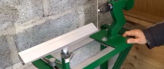
Making a homemade jointing machine
Side wall
First of all, we will make a side wall, for this we use plywood 18-20mm thick with dimensions 150x480mm. By cutting out a place in the workpiece in which the electric planer will be fixed. This should be done using an electric or manual jigsaw, since the sample shape has a complex configuration.
Read also: Thicknesser for wood reviews
Using a drilling machine, two grooves should be made in the side panel at a distance of 70 mm, with their help, in the future, the base of the front table will be attached.
Machine base
We make the base. This is a simple rectangle that needs to be cut on a circular saw or other sawing machine from the same plywood 18-20mm thick with dimensions 180x480mm. Everything is simple here - we connect the base and side wall at an angle of 90 degrees with self-tapping screws into the end of the wall.
In the future, the plane will be installed as follows.
Back table
The back table is also made of 18-20mm plywood with dimensions of 150x600mm; a technological opening is cut out to get this shape.
The end edge of the opening must be cut at an angle. This can be done on a circular saw or jigsaw.
Next, unscrewing 4 screws, remove the fixed “sole” from the electric planer and mark the table of the future machine.
Having drilled the necessary technological holes, they need to be countersunk a little so that the standard screws are recessed “flush” and do not interfere with the movement of the workpiece.
We install our homemade back table in place of the removed sole of the electric planer using standard screws. After this, you need to fix this table on the side wall with self-tapping screws into the end of this wall.
Front movable table
The front table, which must be adjustable in height, is made of two rectangular pieces fastened at an angle of 90 degrees. For greater structural strength, you need to make triangular stops between them. In this example, everything is attached with self-tapping screws; however, for greater strength, it is recommended to coat the joints with wood glue. The end result should be a design like this.
At a distance of 70 mm from each other, you need to make two through holes with a diameter of 8-10 mm and hammer furniture drive nuts into them. It is better to do this before assembling the base.
Installation of the movable table is done using two screws on the back of the side wall. For convenience, you can use bandages with a winged head or make homemade holder mounts. The installation should be carried out so that the plane of the moving part of the “sole” of the electric planer is in the same plane as the movable table of the jointer.
Side stop
The side stop is needed to ensure smooth and parallel movement of the workpiece, as well as to establish an exact 90-degree angle between the work table and the stop plane. The stop is made simply - from two parts, which can be made from either plywood or solid wood. In this case, an array is used.
Two rectangular blanks are fastened at an angle of 90 degrees, forming a “corner”. After which it is rigidly attached to the stationary part of the table.
A do-it-yourself jointing machine made from an electric planer is ready for use.
Setting up the spring block
The package of flexible clamping elements is rotated around the main axis by the second rod—the clamping axis. It is parallel to the axis of rotation, fixed at its ends in supports, but the height of its position can be changed (along an arc).
The clamping axis is moved by the master, manually, before planing. Thus, it regulates the force of pressing the material by the spring block (depending on the thickness of the workpiece). The specified position of the movable rod is fixed with a handle (thumbscrew).
Important! The cutting edge of the blades in the upper position should be flush with the working surface of the receiving table. The gap between the edge of the receiving part of the table and the circle that the knife blades describe is permissible no wider than 3 mm.
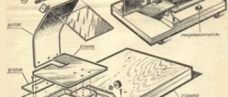
Planing machine drawings
Here are the drawings of the proposed device.
Side wall. View No. 1
Side wall. View No. 2
Front table. View 1
Front table. View 2
Safety when working with homemade equipment
When working with any tool, you must follow safety precautions, as ignoring them can cause various injuries. We will briefly list the recommended measures to ensure the safety of the master’s work on this machine.
- It is recommended to remove sharp chamfers and sand all manufactured parts to eliminate the possibility of hand injury (splinters, etc.)
- When working, it is necessary to use a chip extractor or a special vacuum cleaner, for example, a cyclone type, to remove sawdust and dust from the sawing area, which can cause the following harm:
| To the Master | Respiratory and eye contact |
| Tool | Getting inside the instrument and: |
- deterioration of lubricant properties, resulting in overheating
- difficulty in moving parts of the tool, resulting in overheating
- clogged air passages for cooling the instrument, resulting in overheating
- When working, it is necessary to use pushers, since when working with small parts, it is possible that the master’s hands will get into the cutting zone, which will lead to injury.
Purpose of clamps for a milling machine
Clamping devices are used in drilling, milling and lathes to fix workpieces on the bed, and are necessarily included in the set of tools that equip the equipment. They are able to secure the product so that it can be processed conveniently from any side. Replacing clamping devices with simple yews will not bring the long-awaited result, due to the frequent inability to properly fix the part.
Clamp KREG KMS7511 for milling machine
On the bed of processing machines there are special openings in which milling clamps are bolted. The bolts have special heads that prevent the bolt body from turning and make the connection especially strong.
To achieve a high level of product processing, clamping devices are classified by type of clamp. One clamp installed on the machine is capable of ensuring the accuracy of adjustment associated with numerous transitions when working with different types of parts.
Clamps for milling machines, drilling and other types of equipment must ensure quick and rigid fastening of the workpiece on the side required for work, height adjustment, and free access of the cutting tool to the product. The workpieces processed must meet the following requirements:
- exact location of the material;
- reliable fixation of the part;
- The body of the product allows you to conveniently install clamping devices.
All types of clamping mechanisms must have a high degree of strength and not be deformed under the influence of a screw clamp. Otherwise, the element being processed may jump out and cause harm to the equipment and human health.
The clamping device must hold the part tightly so as not to harm your health while working on the milling machine.