Most finished projects and drawings of public buildings in editable formats are dwg format for AutoCAD. Also available in Inventor, ArhiCAD, Compass-3D and others. Select building type:
Vibrating platforms / Woodworking / Galvanic / For film application / Grinding / Rotators / Manipulators / Friction machines / Winding / Threading / Accessories / Body straightening / Press / Piercing mills / Boring / Cutting / Drilling / Mill / CNC machines / Planing / Lathe / Forming / Milling / Tire / Grinding
Film Applying Machine
Akim
December 19, 2021
- 100
4 255
Working draft. Film application machine. Includes drawings and specifications: machine for applying film assembly drawing, drive shaft assembly, housing, support axle shaft, axle shaft (4 pcs.), flange (4 pcs.), drive axle shaft (2 pcs.), driven shaft assembly, main flange, base (4 pcs), main stand, support (2 pcs), stand (3 pcs), rib, jumper,
Project drawings / Machines
3D parallel
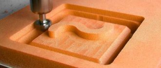
The spiral toolpath did not completely cover the area left by the contour toolpath, so I needed to use a second finishing toolpath to cover the area it missed. This also contributed to a further improvement in surface quality.
Parallel tool path
Modernization of mill 250
Marina Suetkina
August 31, 2021
- 0
251
Graduation project. Contains RPZ and drawings: layout diagram of the equipment of the small-section mill 250, boring boring cutter, hydraulic control unit, mounting plate, drive shaft, winder drum drive, bearing cover, cover (blank), technological adjustment diagram. Modernization by developing a winding device drive and
Metallurgy / Machine tools
Cross planer support
Sergey Suprun
May 29, 2021
- 0
705
Assembling the support of a cross-planing machine. With a 3D model of each part from the assembly separately. The project contains drawings (general view drawing, assembly drawing, folding bar, vernier ring, lead screw, specification) and 3D models (cross-planing machine support, soldier, slide, handle, folding bar, flywheel, housing, vernier ring,
Machines / KOMPAS-3D
Parts design. Gathering all available information for design
Result: Collect and systematize all known information on the future part for convenience during design
Steam motor
One of my inspirations was a beautiful brass model of a steam engine from Engineman.
Organize all sketches, photographs, specifications, or other details about the part. View them, organize them, and make them available for easy use when creating a CAD model.
Another approach to consider is raster tracing or vectorization. If you have photos of a part you want to take, many CAD programs will allow you to upload the photos, scale them, and either trace or automatically vectorize the elements you see in the photos. This way they will be accurately modeled using CAD software.
In some cases, accuracy is not particularly important. For example, when modeling a decorative part in a wood carving application.
Electrical equipment of a lathe
MBSIK
April 30, 2021
- 0
662
Schematic diagram drawing and explanatory note for the course project on MDK 01.03. “Electrical and electromechanical equipment” Completed: schematic diagram of the lathe control, installation diagram of the cabinet, general view of the cabinet. Based on the initial data, the power was calculated and the engine was selected, the mechanical characteristics were calculated
Machine tools / Electrical circuit projects
Pipe feeding manipulator in the OXYGEN converter shop of the Magnitogorsk Iron and Steel Works
termist
February 2, 2021
- 0
804
Includes: PowerPoint presentation, video file with animation of the manipulator, drawings, calculation and explanatory note. The diploma project proposes the modernization of the drive for moving the carriage and the rotation mechanism of the boom of the manipulator of the protective tube at the casting site of CCM No. 4 of the oxygen-converter shop of OJSC MMK (Magnitogorsk
Metallurgy / Machine tools
Tabletop grinder machine for working with sanding belts 1500x50 mm and 1600x50 mm
golubev749
November 20, 2020
- 0
1 499
Tabletop grinder for processing metal, plastic and wood products. The machine is equipped with a three-phase electric motor AIR 71B2 with a rotation speed of 2800 rpm. This motor has the ability to connect to 220 and 380 V networks, according to triangle and star circuits, respectively. When connecting the engine to a 220V network, the machine is equipped with two
Machine tools / 3d models Solidworks
Features of choosing a router design
The capabilities of modern CNC equipment are enormous. But no machine is universal. Each model has its own characteristics and preferred area of application. Before choosing a specific design, you should clearly determine what the machine will be used for. An attempt to combine everything in one will lead to large material and physical costs, without guaranteeing results.
Today, there are two directions in the design of desktop routers. The first, the simplest, is focused on processing wood, plastic and other soft workpieces. Such machines do not place high demands on structural materials and are simple and low in cost. They are available for self-production, without the use of additional equipment. Metal products on such devices are usually not milled. In rare cases, only soft non-ferrous metals are sharpened at low feed rates.
The second direction of milling cutters is focused on working with metal workpieces. These machines have a significant mass and consist of parts that can only be completed using a serious machine park.
It is recommended to undertake such a design yourself only if you have serious experience and access to factory metalworking equipment.
The second most important parameter of the machine is the dimensions of the processed parts. Beginners immediately want a large-sized field on which they can do whatever they want. But the larger the machine, the more technical problems will have to be solved during its design. And its cost will not be the most optimal. If there are no specific tasks for a large machine, then it is recommended in the first project to limit the processing field to the size of a standard A4 paper sheet. The maximum you can choose is A3.
Grinder grinding machine
rustik427
October 21, 2020
- 0
1 721
Parts drawings + 3d model. Tabletop grinder for processing metal, plastic and wood products. Machine for working with sanding belts.
Machines / KOMPAS-3D
Set the X and Y axes to zero
For my part, since I had plenty of extra stock, I only needed to mark the center of the piece with pencil lines. I then used a pointed tool to grab the pencil cross to set the X and Y axis zero points.
The excess stock gave me enough room for error to keep the finished shape within the confines of the piece of raw wood I used.
Workpiece in the machine
PROJECT OF ORGANIZING CAR SERVICE FOR PASSENGER VEHICLES IN VOLOZHIN
atf_rulezz
October 10, 2020
- 0
1 616
According to the assignment, the maintenance and repair zone for passenger cars was developed in detail. As a result, the area of the zone is 54 m2. In the design part, a VolvoS90 steering simulator was developed. A technological map has been compiled for replacing timing elements of the PSA DW8P engine.
Design of enterprises, sites, workshops / Machine tools
AUTOMATED ELECTRIC DRIVE OF THE MECHANISM FOR MOVEMENT OF THE ROD WITH A STEAMING MILL
Alyona
August 7, 2020
- 0
801
The diploma project briefly outlines the features of the technological process for producing pipes using a pipe rolling unit. The power calculation and selection of the motor for the automated electric drive of the mechanism for moving the rod with the mandrel of the piercing mill, and the calculation of the position controller were carried out. The mathematical model of the power section has been calculated
Automation, electronics / Machine tools
3D outline
This path is ideal for finishing steep walls, so I first used it to finish the outside of the model.
Testing is the key to learning, so make adjustments and test.
If you're unsure, the software usually sets the values fine, so you can leave most of the options as they are.
Contour tool paths on the model
Repair of silicate press SM-816
Alyona
July 16, 2020
- 0
734
In the course project, the labor intensity of repairs was calculated, and a repair and lubrication flow chart was made. The operating principle, purpose and design of the SM-816 press are described, a description of equipment lubrication is made, possible failures are indicated, and the planning and organization of repairs is described.
Project drawings / Machines
Adding dimensions, tolerances, and notes
Result: perfect CAD model with specified dimensions, tolerances and notes
The goal is to add all the dimensions, tolerances, and notes needed to convey additional information. It will be important to ensure that the manufactured part meets the designer's goals and specifications.
Modern CNC designers use geometric dimensions and tolerances (GD&T) as a standard.
Keep tolerances as loose as possible. It's tempting to specify very tight tolerances, but they can significantly increase the cost of making a part without need or any real benefit.
