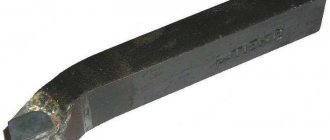
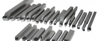
A cutting cutter is a type of turning tool designed for through cutting of a workpiece with a narrow and deep groove. Such cutters are most often used to separate the machined part from the bar fed through a hole in the spindle. In their design, they differ from through, boring, threaded and other metal turning tools, which is due to the specific operation of their cutting edge. The cutting operation takes up a small part of the total processing time of the part, but, as a rule, it is the last in the work cycle, and therefore the quality of the end of the part depends on it. Incorrect choice of sharpening angles for the cutting plate increases the risk of unevenness and chipping on the cut surface, which can lead to defective parts or the impossibility of further processing. One of the main features of a cutting turning tool is that its head part during processing is immersed in a narrow groove, the transverse dimension of which is slightly larger than the width of the cutting edge blade. This creates certain difficulties for chip removal and tool cooling and therefore requires special design solutions.
Cut-off lathe device
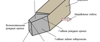
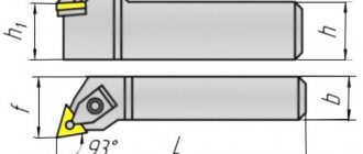
Structurally, an all-metal cutting turning tool consists of a massive holder and a flat head ending with a cutting plate (see the left drawing in the figure below). Unlike other types of cutting tools, here, in addition to the main cutting edge, there are also two auxiliary ones, which are located on both sides of it and are intended for trimming the side surfaces of the groove being cut. In a cutting cutter, the blade tapers towards the holder at angles from 1º to 3º on each side. This is done in order to reduce friction between the cutter and the groove walls, as well as improve chip control and coolant circulation.
The width of the head blade can be from 3 to 10 mm, and its length must be selected several millimeters greater than the radius of the workpiece. To increase strength and reduce vibration, special models of cutting tools with an enlarged front part are used.
Balance is given to such a tool by heads that have a rounded protrusion at the top (“cockerel”), which allows the cutting edge to be positioned in line with the axis of the holder (see the lower right drawing in the figure above).
Types and purpose of cutting tools
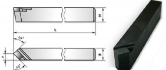
According to their design, cutting tools are divided into all-metal and prefabricated. The first ones are made of tool steel, and their standard sizes and designation rules are regulated by GOST 18874-73. The maximum GOST dimensions of such a cutter are: total length - 80 mm, head length - 15 mm, blade width - 12 mm. With this tool, as the cutting edge is sharpened, the length of the head decreases and, consequently, the maximum cutting diameter decreases.
Prefabricated cutting tools can be divided into two main types. The first includes a cutting tool in which the holder and head are made of one piece of metal, and the cutting plate is a separate assembly element mounted at the end of the head. There are two main types of fastening, according to which cutters with mechanical and soldered fastening of plates are distinguished. The second type is a prefabricated cutting tool that has recently become widespread, in which a flat and long head with a cutting part is mechanically attached to a special mandrel that acts as a holder (see figure below). These cutters come with replaceable inserts of varying widths and thicknesses. In addition, some of them have adjustable head extension length.
In addition to normal and reinforced cutting tools of traditional design, there are a number of varieties for working in special conditions, including those that compensate for the shortcomings of low-power and non-rigid turning equipment. These include spring and inverted cutters, which are mainly used in home workshops and small industries. Spring cutters have an arched head and are designed for processing materials with an uneven and hard surface on small machines with a flexible structure. This head compensates for dynamic shocks and smoothes out vibration, which allows you to achieve the desired surface quality and protect the cutting insert from damage.
Inverted cutters became popular five or six years ago when a very easy to use and efficient cutting insert was developed.
Features and advantages of inverted cutting tools
This type of cutting tool got its name due to the fact that it operates on a reverse (counterclockwise) spindle rotation. The design itself resembles a stationery knife: a holder and a long blade in the form of a plate with a bevel at the end. The blade is made of high-speed steel alloyed with cobalt and in cross-section looks like an inverted letter “T” with short crossbars (see picture below). The sharpening angle of the end of the cutting edge is 7º, the size range of thicknesses produced by the manufacturer is from 1 to 3.2 mm.
The main advantage of this cutter is the facilitated removal of chips, since when the spindle rotates in reverse, it immediately goes down under its own weight. With this mode, the likelihood of clogging the groove with chips is sharply reduced, which is often the cause of jamming and tool breakage. Other advantages of this model include:
- ease of sharpening the blade;
- work at long reach;
- improved cooling mode (chips from below, coolant from above);
- long service life even with repeated sharpening of the plate.
In addition, its arbor has a precise height adjustment system, which eliminates the need to adjust the position of the tool using shims.
Tool holders
Details Category:
CUTTER HOLDERS
, ornamental steel mandrels into which short pieces of high-speed steel are inserted to serve as cutters. They are used for processing metals instead of ordinary cutters, both in order to save expensive high-speed steel and simplify the point (single-cut holders), and to reduce processing time (multi-cut holders). Ordinary tool holders are made from ordinary carbon steel, usually by die forging, and are equipped with a device for clamping a short piece of tool or high-speed steel that serves as a cutter. Based on the position of the cutter, three types of cutter holders are distinguished: a) with a horizontal arrangement of the insert cutter, b) with a slope equal to the angle of the upper working surface of the cutter, and c) with a slope equal to the angle of the front sharpening. In the first case, it is necessary to grind the entire shape of the tip; in both of the latter cases, only the end surface of the insert cutter is sharpened. Cutting holders of the first type are used, Ch. Thus, for cutting cutters (Fig. 1, c), as well as for piece production, since they allow different materials to be processed with different insert cutters. For mass production, cutter holders of the last two types are more suitable, and, however, for processing different types of materials, different cutter holders with a corresponding cutter inclination are required (see Cutters). Strengthening the insert cutter into the cutter holder should allow it to be adjusted in height and ensure sufficient immobility of the cutter during operation; To do this, in addition to a reliable clamping device, it is necessary to reduce as much as possible the overhang of the cutter and the tool holder.
The number of forms of cutting holders is very large. In fig. 1 shows several typical examples of tool holders: a - for heavy work on lathes and planers, b - with an eccentric self-tightening clamp, c - cutting-off, d - spring, e - for round shaped cutters, f - for tangential shaped cutters, g - a holder in which the cutter is clamped directly by the tool clamp of the caliper, h - a holder for internal boring.
In mass production, multi-cut holders are often used, which process the entire surface of the object to be turned in one clamp in one slide stroke. In fig. Figure 2 shows the processing of the axial journal of the front wheel of a car using two cutting holders: one for longitudinal turning, the other for transverse turning.
The body of these tool holders is made either from the best dense cast iron or from cast steel. Multi-tool holders are most widely used in turret and automatic lathes.
The advantages of single-cut holders are: reduction in the cost of the cutter, significant lightening of its point and unconditional accuracy of the blade angles, independent of the worker. The first has almost lost its meaning since the introduction of cutters with welded blades made of high-speed steel or stellite. The disadvantage of cutter holders is significantly worse heat dissipation and reduced rigidity compared to solid cutters of equal cross-section. Therefore, the use of tool holders for heavy turning and planing work is impractical.
Source: Martens. Technical encyclopedia. Volume 6 - 1929
- < Back
- Forward >
Markings used
There are three GOSTs that establish rules for marking cutting tools. The standard sizes and coding of tools made of high-speed steel are regulated by GOST 18874-73, with carbide plates - GOST 18884-73, curved (“cockerel”) with carbide plates - GOST 18894-73. It is impossible to determine the type and geometry from markings without using GOST tables. In all three standards, each type has its own code and group of parameters, listed in tables. The only informative element of the marking is the designation of the carbide of the cutting insert. For example, a right-hand quick cutter with a cross-section of 16×16 mm, a length of 80 mm, a head of 15 m and a blade width of 12 mm is designated as 2120-0519 GOST 18874-73. The remaining two GOSTs adhere to the same marking system. A cutting cutter with a similar geometry with a carbide plate is designated 2130-0255 T5K10 GOST 18884-73, where T5K10 is a hard alloy with titanium carbide and cobalt (the numbers are percentages). Some manufacturers, in accordance with international standards, mark the type of insert material with color (applied to the end of the holder). For example, T5K10 is indicated in yellow.
In addition to GOST, there is a universal international system for designating cutting tools ISO. This is a lengthy document with many tables containing the characteristics of indexable inserts, so it is only appropriate to give here an example of the marking of a parting cutter with indexable inserts, which belongs to the group “External parting and grooving”: QFGD2525R2252H. Decoding of code positions:
- Q – cutting holder.
- F – end processing.
- G – plate size.
- D – for double-sided plates.
- 25 – holder height.
- 25 – holder width.
- R – right, neutral, left.
- 22 – maximum processing depth.
- 52 – minimum cutting diameter.
- H – position of the insert when machining face grooves.
The ISO standard partially or completely repeats the marking systems of leading manufacturers of cutting tools, as well as the new Russian GOST ISO 5609-2015.
LEFT TURNING CUTTERS FROM HIGH-SPEED STEEL (Р6М5, Р18) GOST 18874-73
| Cutting cutter 2130-0501/0502 6x6x50, a=1.5 | Price on request Buy |
| Cutting cutter 2130-0503/0504 8x8x50, a=2 | Price on request Buy |
| Cutting cutter 2130-0505/0506 10x10x60, a=2 | Price on request Buy |
| Cutting cutter 2130-0507/0508 12x12x70, a=3 | Price on request Buy |
| Cutting cutter 2130-0509/0510 16x10x100, a=3 | Price on request Buy |
| Cutting cutter 2130-0511/0512 20x12x120, a=3 | Price on request Buy |
| Cutting cutter 2130-0513/0514 20x12x120, a=4 | Price on request Buy |
| Cutting cutter 2130-0515/0516 25x16x140, a=3 | Price on request Buy |
| Cutting cutter 2130-0517/0518 25x16x140, a=5 | Price on request Buy |
| Cutting cutter 2130-0519/0520 32x20x170, a=4 | Price on request Buy |
| Cutting cutter 2130-0521/0522 32x20x170, a=6 | Price on request Buy |
| Cutting cutter 2130-0401/0402 20x12x120, a=4 | Price on request Buy |
| Cutting cutter 2130-0403/0404 25x16x140, a=5 | Price on request Buy |
| Cutting cutter 2130-0405/0406 32x20x170, a=4 | Price on request Buy |
| Cutting cutter 2130-0407/0408 32x20x170, a=8 | Price on request Buy |
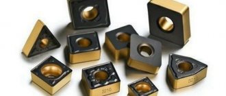
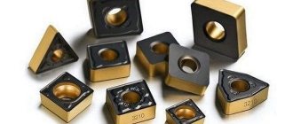
Advantages of carbide inserts for cutters
The main advantages of carbide inserts for cutting tools over high-speed cutting tools are the ability to work with high cutting speeds (up to 500 m/s for steel) and maintaining hardness at high (up to 900 °C) temperatures in the processing zone. There are two main methods for securing carbide inserts to the head of a holder: soldering (as well as similar methods) and mechanical fastening. Permanent connections are structurally simpler and more resistant to vibration when operating under heavy loads. But, despite the more complex manufacturing technology, a cutting tool with plate fastening mechanically has a number of undeniable advantages:
- no thermal effect on the holder head during fastening of the cutting part;
- the ability to quickly replace the plate or rotate with another cutting edge;
- use of different types of plates on one type of holder;
- preservation of the geometric characteristics of the cutter after replacing the insert.
In addition to cutting elements made of hard alloys, ceramic plates are used when processing particularly hard materials. They are more fragile, but are characterized by increased wear resistance of the cutting edge and can operate at very high temperatures in the cutting zone (up to 1200 °C).
Turning cutters through passage.
Used for semi-finish and finishing turning. The plate fastening system is P (lever).
| Designation | h = h 1 | b | f | L | Cutting inserts | Weight, kg | |
| Right | Left | ||||||
| 2102-4036 PSSNR2525M12 | 2102-4036-01 PSSNL2525M12 | 25 | 25 | 32 | 158,3 | 03123-120412 SNMA-120412 | 0,96 |
| -02 PSSNR3225P15 | -03 PSSNL3225P15 | 32 | 180,2 | 03124-150612 SNMM-150612 | 1,08 | ||
| Designation | h = h 1 | b | f | L | Cutting inserts | Weight, kg | |
| Right | Left | ||||||
| 2102-4035 PCLNR2525M16 | 2102-4035-01 PCLNL2525M16 | 25 | 25 | 32 | 150 | 05124-160412 CNMM-160412 | 0,72 |
| -02 PCLNR3225P16 | -03 PCLNL3225P16 | 32 | 170 | 1,06 | |||
| Designation | h = h 1 | b | f | f1 | l | L | Cutting inserts | Weight, kg | |
| Right | Left | ||||||||
| 2109-4009 PTFNR2525M16 | 2109-4009-01 PTFNL2525M16 | 25 | 25 | 32 | 17,4 | 20,2 | 150 | 01124-160408 TNMM-160408 | 1,43 |
| -02 PTFNR2525M22 | -03 PTFNL2525M22 | 24,4 | 25,2 | 01124-220408 TNMM-220408 | 1,57 | ||||
| -04 PTFNR3225P22 | -05 PTFNL3225P22 | 32 | 170 | 2,75 | |||||
Recommendations for choosing cutting tools for metal
A cutting lathe is a highly specialized tool and is used to perform only two types of operations: cutting and turning narrow grooves. Therefore, for home and small repair shops, one of the main criteria when choosing it will most likely be price. In the case of a one-time use of this tool, a Russian cut-off cutter with brazing is quite suitable, the price of which is one and a half to two times less than that of one carbide insert with mechanical fastening. In mass production, especially on CNC machines and automatic lathes, either the cutting operation is the final one, or it is followed by the transfer of the part to the sub-spindle for further processing. Under these conditions, special requirements are placed on the geometry and quality of work of the cutting tool, so in such industries there is simply no alternative to high-tech cutters with replaceable inserts.
How to install a parting cutter
In order to perform cutting correctly without increased wear of the cutting plate, as well as to ensure the required quality of the end after cutting, it is necessary to align the cutter strictly perpendicular to the part. In addition, it must be installed opposite the axis of rotation with a vertical deviation of no more than ± 0.1 mm. Placing the edge of the blade even a few tenths of a millimeter higher can cause the cutting blade to break, and placing it too low can leave an uncut step on the workpiece. Cutting must be done as close to the chuck jaws as possible, using a cutter with a minimum overhang.
To facilitate the processing of complex materials on desktop machines, spring and inverted cutters are used. But, probably, craftsmen use other designs for these purposes, as well as various improvements to “standard” cutters. If you know anything about this, please share information in the comments to this article.
Contour turning cutters.
| Cutting insert grade – Composite 09 PTNB. Used for finishing turning of HRC 55…65 steels. |
| Designation | Dimensions , mm | Cutting insert | Weight, kg | |||||||
| Right | Left | λ° | γ° | h | b | L | h1 | f | ||
| 2102-4052К MCLNR 2022 K12 | 2102-4052К -01 MCLNL 2022 K12 | -6 | -6 | 20 | 20 | 125 | 20 | 25 | CNMM-120408 PNTB | 0,9 |
| -02 MCLNR 2525 M12 | -03 MCLNL 2022 M12 | 25 | 25 | 150 | 25 | 32 | 1,3 | |||
| -04 MCLNR 3232 P12 | -05 MCLNL 3232 P12 | 32 | 32 | 170 | 32 | 40 | 1,8 | |||
The difference between modern Composite 09 PTNB is the absence of impurities and high dispersion of the material, produced in two modifications: PTNB-micro grain size 1.0 microns; PTNB - nano grain size 0.1 microns. New tools provide a 5-10-fold increase in processing productivity for hard-to-cut materials, processing accuracy up to 0.5 microns and surface finish up to Ra 0.1 microns without subsequent grinding and finishing operations. The performance characteristics of OJSC OIZ tools are not inferior to similar tools from foreign companies, since they are equipped with composites of significantly finer grain size, which contain less binder fraction and, accordingly, higher physical and mechanical properties. By special order it is possible to produce plates of any other shapes. equipped with composites based on cubic boron nitride and polycrystalline diamond.