Electric arc welding of parts includes two main components. The first is the metal products being connected, the second is the additional metal that connects them. At the same time, it is important to determine the optimal consumption of electrodes per 1 m of seam using a calculator for calculation, which today can be found on the Internet.
The reason here is not only financial, but also technological. The weight of the connecting metal makes the finished product heavier, and this value can reach up to 1.5% of its initial weight.
If this is not important for static elements, then for moving mechanisms it can be significant, even critical.
What does it depend on?
Costs for electrodes, welding wire, etc. used when connecting structural elements, electrical energy consumption is mainly affected by the cross-section of the weld.
In turn, this indicator depends on exactly how the welding is performed, how thick the metal is, and the quality of preparation of the parts.
Important! Even slight moistening of the electrodes sharply increases consumption, reduces the quality of the seam, and makes work more difficult. Store materials exclusively in a dry place, in packaging that prevents the ingress of water.
As a rule, the main characteristic - the leg of the seam, on which its cross-section depends, is determined by the project. From here the required diameter of the welding material, the strength of the welding current, etc. are determined.
If we carefully examine the electric welding process, we will be convinced that not all of the introduced metal is used. Some of it is evaporated by the arc flame, some is sprayed with familiar welding sparks.
A certain amount of metal is bound in the slag covering the seam, formed by molten coating and oxides. These losses are defined by the word “waste” .
Finally, the process technology itself involves holding the electrode. Accordingly, part of it remains unused. Such a piece is technically called a “cinder”; its length is about 50 mm . Part of these costs depends on the location and length of the seam. Losses are also higher when you have to weld many separate sections, for example, when welding reinforcement, than one long seam.
Properties of a quality seam
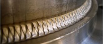
Now we know how to calculate the leg of a weld. But this is not enough to ensure that the connection is guaranteed to be high-quality and reliable. A welded joint has its own properties and features that need to be taken into account. The most important thing is that the seam should be uniform and uniform along its entire length. There should be no deviations to the side or too much welding in certain places.
Control yourself, visual control is available without instruments or special skills. One small flaw can result in the collapse of a metal structure after a while. Also, the width of the seam should be the same. If the width of the seam changes, the loads will be distributed unevenly, which can lead to the formation of cracks and failure of the welded joint.
Also keep an eye on the thickness of the seam (in other words, its depth). The penetration depth must also be uniform to avoid internal cracks. Professional welders in large production literally calculate down to the millimeter the future characteristics of the seam, its thickness, width and length. And they do the work according to these calculations. Of course, this is unnecessary in amateur and semi-amateur welding, but you must understand in advance what kind of seam you need to get in the end.
The more similarities the parts being welded have, the better. Of course, there are methods for welding non-homogeneous metals, the composition of which is very different, but the connection will still never be as strong as when welding homogeneous metals. Set the correct amperage, use professional welding equipment (if you are not welding at an amateur level), select the correct electrodes for welding. Only by observing all this will the calculations make sense. If you make a million calculations, but do not set the correct amperage on the welder, then your efforts will simply go down the drain.
Practical and theoretical calculations
You can calculate consumption in two ways:
- theoretical;
- practical.
In the first case, normative data with varying degrees of approximation are used. The simplest option would be to use departmental consumption standards depending on the type of structure (Table 1). The calculation is based on a ton of finished products.
The method is used for practical purposes, for approximate calculation of consumables for the manufacture of a particular structure.
More accurate data is provided by building codes VSN 416-81 . The norms represent a collection of empirical data summarized in tables. They are compiled for most of the types of pipe joints used, the shape of the seam, and the type of consumables.
An equally accurate result is obtained by calculation using formulas where various correction factors are introduced.
The essence of the practical method is field measurements of actual work. This includes the quality of consumables, the type and capabilities of welding equipment, the qualifications of workers, etc. The method requires more than one hour of labor and materials. Moreover, its results are consistent with parts that closely match the samples.
Consequences of incorrect leg calculations
Errors lead to the following results:
- To a lesser extent. The strength of the seam does not correspond to the design. When exposed to workload, the connection fails.
- On the big side. Materials and energy are used irrationally. The cost of a product or structure increases unjustifiably. This is especially true in mass production. Annual losses can amount to hundreds of thousands of rubles.
In a one-time production of a small-sized structure that is not subject to heavy loads, deviations in one direction or another are not critical. In this case, the seam leg can be selected approximately.
A large structure, under load from a large dead weight and heavy mechanisms, requires a different approach.
Leg and other parameters of welds are calculated with great accuracy and in accordance with GOST requirements. Otherwise, the structure may collapse.
Errors
The calculations themselves cannot be inaccurate. But the initial data is fine.
- Table values are taken based on average indicators; in fact, they can differ significantly.
- The data entered into the formulas is determined by measurements. At the same time, errors in the instruments themselves and in the measurement methods are possible.
- Sample data does not match. This is caused by different preparation accuracy, deviations in seam size, etc.
All of the above deviations can accumulate and in practice reach 5-7% . It is this amount of welding material that is recommended to be kept as a reserve.
Influence of welding speed and mode
There is a dependence of the weld cross-section configuration on the process parameters:
- As the current increases at a constant voltage, the temperature increases, so the penetration depth becomes greater. But with excessive amperage, metal can be burned.
- An increase in voltage at a constant current leads to an increase in the length. If there is an excess, lack of penetration is possible.
- As the speed of movement of the electrode increases, the heating temperature of the metal decreases. The seam width and penetration depth are reduced. At speeds above 50 m/h, the lack of temperature leads to the formation of defects that make the seam weak.
- The viscosity of the electrode material affects the shape of the amplification. The higher it is, the more convex the surfacing becomes.
We recommend reading Features of an overlap welding joint
The welding mode is selected according to the workpiece with the smallest thickness, so as not to burn through it.
Formulas used in calculations. Correction factors
The formula used to calculate the consumption rate is as follows:
(1) NE = GE * LSH;
where NE is the flow rate itself, which needs to be determined; GE – specific norm; LШ – seam length in meters.
GE is calculated using formula (2) : GE = kр * mн. Here: kр – correction tabular set, taking into account losses due to waste, devices of “idle rollers” (correction surfacing), cinders, preliminary tacks, etc. Its value depends on the group and brand of consumables (Table 2)
(3) mн = ρ * Fн, Where ρ is the specific density of steel. Depending on the type of consumables, it is accepted: The value mn is the weight (mass) of the deposited metal, determined by the formula:
- 7.5 g/cm3 (7500 kg/m3) when using welding wire, thin-coated or bare rods;
- 7.85 g/cm3 (7850 kg/m3), for thick coated electrodes.
Fн – cross-section of the deposited weld metal cm2. The value is calculated using tabular data from GOST 5264-80, or using independent measurements.
How to calculate a weld leg
There are a huge number of formulas with which you can calculate the leg of a seam. Along with them, there are various types of seams: butt, T, lap, corner, and each type has its own subtypes. It turns out that there is a formula for each type of seam, and there are about a dozen of them (taking into account all the features, of course). We will not be able to reveal them all within the framework of this article, so we will tell you how to calculate the leg by the width of the seam, since this is the most popular and frequently used formula.
T is our leg
S is the width of our seam
cos45° is a cosine equal to 45 degrees (the value is unchanged, cos45°= approximately 0.7)
That's the whole formula. It is easy to find out the size of the fillet weld leg, for example. Because essentially the leg of the corner joint is equal to the leg of the triangle that we can inscribe.
We will not calculate the leg of the weld based on the thickness of the metal, since even formulas are not needed here. You just need to take the value for the smallest thickness and this will be our answer. A simple example: we have metal 3 millimeters thick. We need to connect it. We will determine the leg by thickness. Just make sure that the thickness of the metal is really 3 millimeters around the entire perimeter and use this value. Calculating the leg of the weld based on the thickness of the metal is very convenient if lap welds are used and the parts are quite thin. If the parts are thick, then simply calculate 40% of the thickness.
Below is a table of the minimum weld lengths for welded joints. It will be useful if you do not have the opportunity to make a quick calculation. Save it for yourself and try to use it in your work.
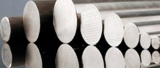
How much is contained in 1 kg?
As a rule, the weight of the pack is not strictly regulated, but usually this value is 1, 5, 6 or 8 kg. The exact weight is indicated on the packaging itself .
Depending on the diameter of the rod, the pack contains a different number of products. If this value is not indicated on the label, it can be calculated based on the weight of one rod.
If you don’t have a table at hand, you can get your bearings as follows. We multiply the length (usually 45 cm) by the cross-sectional area, determined by the formula for the area of a circle: S=πR2. We multiply the obtained result with the volumetric weight of steel 7.85 g/cm3.
The weight of an electrode with a diameter of 4 mm will be about 61g. Dividing 1 kg by 0.06 we get 16 pieces.
Determination of cross-sectional areas of welds
| Cross-sectional shape | Calculation formula | |
| Prepared edges | Completed seam | |
2.7.6. Welding technique
The technique for making welds depends on the type and spatial position of the seam.
Bottom welds are the most convenient to perform, since the molten metal of the electrode flows into the crater under the influence of gravity and does not flow out of the weld pool, and gases and slag come out to the surface of the metal. Therefore, whenever possible, welding should be done in the lower position. Butt welds without beveled edges are made by surfacing along the bead seam with a slight widening. Good penetration of the welded edges is necessary. The seam is made with reinforcement (seam convexity up to 2 mm). After welding the seam on one side, the product is turned over and, having thoroughly cleaned of smudges and slag, the seam is welded on the other side.
3. Fig. 45.
Welding of butt seams with a V-shaped groove for edge thicknesses up to 8 mm is carried out in one layer, and for large thicknesses - in two layers or more. The first layer is deposited with a height of 3 ... 5 mm with an electrode with a diameter of 3 ... 4 mm. Subsequent layers are made with an electrode with a diameter of 4...5 mm. Before surfacing the next layer, it is necessary to thoroughly clean the groove of the seam from slag and metal splashes with a wire brush. After filling the entire seam groove, the product is turned over and a small groove is selected at the root of the seam, which is then carefully welded. If it is impossible to weld the seam on the back side, you should especially carefully weld the first seam. Butt welds with an X-shaped groove are performed similarly to multi-layer seams on both sides of the groove. It is better to make corner seams in the lower position in the “boat” position (Fig. 45, a). If the product cannot be installed this way, it is necessary to especially carefully ensure good penetration of the root of the seam and the welded edges. Welding should begin from the surface of the lower edge and then proceed through the groove to the vertical edge, as shown in Fig. 45, b. When applying a multilayer seam, the first roller is made with a thread seam using an electrode with a diameter of 3 ... 4 mm. In this case, it is necessary to ensure good penetration of the root of the seam. Then, after cleaning the groove, subsequent layers are deposited.
Vertical seams are less convenient to weld, since gravity drags drops of electrode metal down. Vertical seams should be made with a short arc and from bottom to top (Fig. 45, c). In this case, drops of metal move more easily into the seam, and the resulting shelf keeps further drops of metal from flowing down. Welding can also be done from top to bottom. In this case, the arc should be ignited with the electrode position perpendicular to the plane of the product (position I, Fig. 45, d). After the first drops of metal have formed, the electrode is tilted down II and welding is performed with as short an arc as possible. It is recommended to use electrodes with a diameter of 4 ... 5 mm at a slightly reduced welding current (150 ... 170 A).
Horizontal seams - to perform them, prepare edges with a one-sided bevel at the top sheet (Fig. 45, d). The arc is excited at the lower edge and then transferred to the bevel surface and back. Welding is performed with an electrode with a diameter of 4 ... 5 mm. Horizontal overlap welds (Fig. 45, e) are easier to make, since the lower edge forms a shelf that holds drops of molten metal.
Ceiling seams are the most difficult to make and therefore require a highly qualified welder. Electrodes with a diameter of no more than 5 mm are used at a reduced welding current. A refractory coating of the electrode should be used, forming a “case” in which the molten metal of the electrode is held. The arc should be as short as possible to facilitate the transition of electrode metal droplets into the weld crater.
The choice of method and order of welding depends mainly on the thickness of the metal and the length of the seam. When welding thin-sheet steel, strict adherence to the welding technique is necessary. Of particular danger are through burns and metal penetration.
Rice. 46.
Steel with a thickness of 0.5 ... 1.0 mm should be overlap welded with penetration through the top sheet (Fig. 46, a) or end-to-end with laying between the welded edges of the steel strip (Fig. 46, b). In the second case, the melting of the edges should occur under the indirect influence of the arc. Welding is carried out at reduced conditions. The arc is powered by a PS-100-1 converter or a TS-120 alternating current device, as they are characterized by increased no-load voltage and low welding currents.
Coated electrodes of the MT or OMA-2 brands are used. Welding is carried out on massive heat-dissipating copper pads. This method of heat removal protects the metal from burn-through and promotes good formation of the seam. Thin sheet steel can be welded with flanged edges (Fig. 46, c). Welding is carried out with direct current with a non-consumable electrode (carbon or graphite) with a diameter of 6... 10 mm at a welding current of 120... 160 A. The use of other methods for welding thin-sheet material is discussed in the relevant chapters.
Rice. 47.
Thick metal is welded in several passes, filling the edges in layers. With a metal thickness of 15 ... 20 mm, welding is performed in sections using the double-layer method (Fig. 47, a). The seam is divided into sections 250...300 mm long and each section is welded in a double layer. The second layer is applied after removing the slag over the uncooled first one. When the metal thickness is 20 ... 25 mm or more, cascade welding (Fig. 47, b) or hill welding (Fig. 47, c) is used. The cascade method is as follows. The entire seam is divided into sections and welding is carried out continuously. Having finished welding the layer in the first section, weld the first layer in the second section and continue welding in the first section, applying the second layer over the uncooled first layer, etc. Slide welding is a type of cascade welding, usually performed by two welders simultaneously and carried out from the middle of the seam to the edges. Such welding methods provide a more uniform temperature distribution and a significant reduction in welding deformations.
Rice. 48.
Methods for making lengthwise welds depend on their length. Conventionally, it is customary to distinguish between: short seams up to 250 mm long, medium seams 250...1000 mm long and long seams over 1000 mm long. Short seams are made by pass welding (Fig. 48, a). Medium-length seams are welded either from the middle to the edges (Fig. 48, b) or in a reverse-step manner (Fig. 48, c). The reverse-step method is that the entire seam is divided into sections and each section is welded in the direction opposite to the general welding direction. The end of each section coincides with the beginning of the previous one. The length of the section is selected within the range of 100... 300 mm, depending on the thickness of the metal and the rigidity of the structure being welded. Long seams are also welded using a reverse-step method.
Welding at low temperatures has the following main features. Steels change their mechanical properties, impact strength decreases and the bend angle decreases, plastic properties deteriorate and fragility slightly increases, and hence the tendency to cracks. This is especially noticeable in steels containing more than 0.3% carbon, as well as in alloy steels prone to hardening. The metal of the weld pool cools much faster, and this leads to an increased content of gases and slag inclusions and, as a consequence, to a decrease in the mechanical properties of the weld metal. In this regard, the following restrictions have been established for welding work at low temperatures. Welding steel with a thickness of more than 40 mm at a temperature of 0°C is allowed only with heating. Heating is necessary for steels with a thickness of 30 ... 40 mm at temperatures below - 10 ° C, for steels with a thickness of 16 ... 30 mm at temperatures below - 20 ° C and for steels with a thickness of less than 16 mm at temperatures below - 30 ° C.
Burners, induction furnaces and other heating devices are used for heating. Welding is carried out using electrodes of the E42A, E46A, E50A types, which ensure high ductility and toughness of the weld metal. Welding current is 15...20% higher than normal. The workplace must be protected from wind and snow.
2.7.6. Measures to combat welding stresses and deformations.
Welding creates its own stresses in products. Self-stresses are stresses that exist in a product without the application of external forces. Depending on the reason that caused the stress, there are:
- Thermal stresses caused by uneven temperature distribution during welding
- Structural stresses arising as a result of structural transformations, accompanied by overcooling of austenite in the heat-affected zone and the formation of martensite hardening products, the volume of which is greater than the volume of the original structure.
Heating during welding leads to changes in both the physical and mechanical characteristics of the metal, which must be taken into account.
The entire range of measures to combat deformations and stresses from welding can be divided into two main groups:
- Measures that prevent the likelihood of deformations and stresses or reduce their impact
- Measures to ensure subsequent correction of deformations and relief of stresses
The first group of measures includes: choosing the correct sequence for welding the product, fastening, preliminary bending, heating, intensive cooling of parts and others.
The most effective way is heating. It can be general and local. Heating reduces the unevenness of temperature distribution and thereby can reduce or eliminate the effect of the main factor causing welding stresses and deformations.
To completely relieve stress, heat treatment is used after welding.
To relieve stress, a high vacation is prescribed. The feasibility of prescribing heat treatment for welded structures in each specific case is determined depending on the materials used, the manufacturing technology of the structures and its operating conditions.
The second group of measures includes mechanical and thermal straightening.
Mechanical straightening involves stretching areas of a deformed part. Thermal straightening, i.e. straightening by heating is achieved due to plastic compressive deformations of the stretched sections.
Certain measures are selected depending on the design of the product, the material being welded and the welding method
The magnitude and nature of welding stresses and deformations are determined by the influence of a number of technological and design factors.
Selecting a welding method.
A high concentration of heat helps to narrow the zone of plastic deformation and reduce the deformation of the entire structure. Permanent deformation can be reduced by replacing manual arc welding with covered electrodes with mechanized submerged arc welding using shielding gas or flux-cored wire.
Choosing the shape w in a.
All other things being equal, the X-shaped edge preparation, due to the symmetrical shape of the seam, causes less angular deformation than the V-shaped one. In order to reduce deformations, it is advisable to use double-sided welding in joints without beveled edges.
An effective measure to reduce deformations when welding joints with fillet welds is to reduce the cross-section of the weld through the use of welding materials that provide higher strength to the weld metal.
Selecting the welding mode.
The magnitude and nature of welding stresses and residual deformations are directly dependent on the welding energy input, which is determined by the selected mode.
An increase in the cross-sectional area of a seam or a separate layer in a seam leads to a noticeable increase in residual deformations. To ensure minimal deformation when designing a welded structure, preference should be given to welds with the smallest cross-sectional area (based on the structural strength requirements).
Execution Sequence
seams. The magnitude of residual deformations and stresses arising during welding is significantly influenced by the order of application of seams along the length of the joint and its cross-section.
The most significant deformations are typical for pass welding, so it is advisable to make seams from the middle of the sheets to the edges when two welders work. Reverse-stage welding reduces the amount of stress and deformation. In this case, the seam is welded in sections so that by the start of welding of the next section the temperature of the previous section is not higher than the specified value (200...300°C for steels). In single-layer welding, this condition is met if the length of the step and the section welded with one electrode is the same (with a cross-sectional area of the weld that is 20% larger than the cross-sectional area of the electrode rod).
To reduce the magnitude of residual stresses and deformations when welding multi-pass seams, the cascade welding method is used. The length and direction of welding of individual seams have a significant influence on the magnitude of stresses and residual deformations.
Preliminary bending of welded parts.
This technique is used to prevent angular deformations when welding butt and overlap joints.
When welding sheets of small width with a V-shaped groove of the edges, they are placed not in the same plane, but at an angle to each other so that the protrusion is directed in the direction opposite to the expected deformation (Fig. 2.5, a).
Sheets of large width can be laid with preliminary bending of the welded edges (Fig. 2.5,
b).
It is recommended to weld assembly joints with fixed sheets by first bending the edges (Fig. 2.6, a).
This can be achieved by using jacks or special devices.
To prevent angular deformations of T-joints or I-beams, elastic or plastic deformation of the belt is performed (Fig. 2.6, b).
In order to eliminate longitudinal deformations “in the plane” when welding T-beams, devices are used that bend the beam in the direction opposite to the expected deformation (Fig. 2.6,
c).
Preliminary reverse bending can be created by peening the edges and walls of the beams or by heating to a temperature of 700... 750 °C.
An effective measure to prevent web buckling in an I-beam caused by welding of the flange seams is assembly with pre-tensioning of the web. For this purpose, assembly stands with a jacking device are used. Deformation of thin sheets can be reduced by corrugating them on presses or by pre-stretching the parts being welded along the welding direction.
Cooling of welded parts.
Thanks to additional cooling, residual deformations and stresses are reduced, however, when welding hardening steels, the artificial cooling method is not applicable, since brittle hardening structures can be obtained.
Heating the metal being welded.
With preliminary or accompanying heating, the temperature difference between adjacent sections of the welded joint decreases and the stresses are slightly reduced. Such heating can be carried out by induction, gas flame or electric heaters. When welding steels heated to a temperature of 200 °C, residual stresses are reduced by 30% compared to welding without heating. Both general and local accompanying heating can be carried out. With local heating, a 40...50 mm wide area on both sides of the seam is heated.
In the case of manufacturing particularly critical structures from low-carbon steels with a metal thickness of more than 40 mm, preheating is carried out to a temperature of 100... 120 °C. When welding medium-carbon and low-alloy structural steels, it is advisable to use preheating to a temperature of 150...200°C with a metal thickness of more than 30 mm. If during the welding process it is not possible to reduce stresses and deformations to a given level, it becomes necessary to eliminate them by processing the welded structure.
Heat treatment.
To relieve stress, a welded joint made of carbon structural steels is subjected to a general high tempering (heating to 630...650°C with holding at this temperature at the rate of 2...3 minutes per 1 mm of metal thickness). The cooling must be slow so that stress does not arise again. Therefore, the part is cooled to a temperature of 300 °C with a furnace, and then in still air.
Relaxation (relief) of welding stresses during high tempering occurs due to a decrease in the yield strength of steel at a temperature of 600 °C; as a result, the material has practically no resistance to plastic deformation.
In some cases, it is possible to limit oneself to high tempering of individual structural elements, and usually when welding products made of steel with a low carbon content and alloying elements, preliminary local or general heating without subsequent heat treatment is sufficient.
Argon arc treatment with non-consumable electrode.
Such processing of a section of metal along the fusion line changes stresses due to the transition of part of the metal to a plastic state.
Melting a small amount of base metal and weld metal leads to a reduction in stress by 60... 70%. The resulting smooth transition from the seam to the base metal helps to increase the strength of welded joints, especially under dynamic loading.
Forging of weld metal and heat-affected zone.
Welding stresses can be relieved almost completely if additional plastic deformations are created in the welding zone. Forging of welds on steels is carried out during the cooling of the metal at temperatures above 450 °C or below 150 °C. In the temperature range of 200...400°C, due to the reduced ductility of the metal during forging, the formation of tears is possible. As a rule, special heating of the welded joint is not required to perform this operation. The blows are applied manually with a hammer weighing 0.6 ... 1.2 kg with a rounded striker or a pneumatic hammer with little force. When multilayer welding, each layer is forged, with the exception of the first, in which cracks may appear from the impact. The same technique is used to relieve stress when welding cracks and closing seams in rigid structures.
Thermal straightening.
Heating of the deformed material is carried out with an oxygen gas flame or an electric arc using a non-consumable electrode. The heating temperature of the repaired section of the steel structure is 750...850 °C. In the case of deformation of a thin sheet welded to a massive frame, straightening can be carried out by heating it at symmetrically located points on the convex side. Heating should begin from the center of the bulge.
Mechanical straightening.
To eliminate deformation, mechanical straightening can be carried out using presses or, for metal thicknesses up to 3 mm, manually using hammer blows. This method is inferior to thermal straightening, and its use should be limited, since local hardening is formed, which increases the yield strength of the metal; the plastic properties of the metal deteriorate, which is especially dangerous when the structure is dynamically loaded.
6.7. Quality control of welded joints
When choosing control methods during the preparation, assembly and welding of welded structures, it is necessary to adopt such methods for monitoring the quality of products that would ensure the requirements of the technical specifications for the manufacture of welded structures.
High quality of welded structures can be ensured subject to strict adherence to operational control. Control operations are divided into three stages:
- preliminary control before welding. It includes checking the raw materials used to manufacture the product, checking welding equipment, fixtures, tools, qualifications of welders, etc.
- control during the production process in order to check the correctness of the workpiece, assembly, compliance with technological conditions, size and quality of welds, the sequence of their application, etc.
- control of finished products - acceptance tests
Control at the first two stages helps prevent defects. Before production of welded structures begins, all materials used must be carefully checked. The finished product is checked in accordance with the technical specifications and drawings, as well as by carrying out the prescribed tests.
Having chosen control methods, you should give a brief description and rationale for them.
2.8.Safety precautions when performing assembly and welding work
When assembling welded structures, the following requirements must be observed:
o all processed products must be installed and securely secured in the fixtures
o use only proven lifting and transport equipment
o when working together with electric welders, you need to use glasses or a mask with dark glasses
o when sharpening a tool on sandpaper without a protective screen and when working with a grinder, work in glasses with transparent lenses
When welding, the following requirements should be followed:
o work should only be carried out with a shield or mask that covers all parts of the worker’s face and is equipped with the necessary light-protective glass
o workwear must meet established standards
o to protect others from the action of an electric arc, the electric welder’s workplace must be fenced
o the connection of wires to the product being welded, the electrode holder and welding installations must be tight and durable
o for welding currents exceeding 600 A, the current-carrying wire must be connected to the electrode holder, bypassing its handle
o the handle of the electrode holder must be made of dielectric and heat-insulating material
o to protect against flux dust released during welding, flux ejectors are used, and the workplace is provided with ventilation
o torches for welding in carbon dioxide must not have exposed live parts, and the handles must be covered with dielectric heat-insulating material
o if sparking occurs between the torch body and the workpiece, welding must be stopped until the problem is resolved
o gas and water communications must be sealed and have no gas or water leaks
The main fire protection measures are: the presence of serviceable electrical wiring, welding wires and other sources, the absence of flammable substances when working on the site, compliance with all requirements of fire safety regulations by all workers on the site.
BIBLIOGRAPHY
1. Kurkin S.A. , Nikolaev G.A. Welded structures - M: Higher School, 1991
2. Ryzhkov N.I. Production of welded structures in heavy engineering - M: 1980
3. Dumov S.I. Electric fusion welding technology - L: Mechanical engineering. Leningrad branch, 1987
4. Welding in mechanical engineering. Handbook ed. V.A. Vinokurova - M, 1978
5. Gitlevich A.D., Etingof L.A. Mechanization and automation of welding production - M: Mechanical Engineering, 1979
6. Maslov B.G., Vybornov A.P. Production of welded structures - M: Academy, 2008
APPLICATION
Consumption per ton of metal structures
In practice, it is often necessary to consume electrodes per 1 ton of metal structures, but an online calculator may not be available.
Very approximately, it can be taken as 0.9 - 1.2% of the mass of the product. Table 1 (see above) will give us more accurate data.
Sufficiently accurate data is obtained by calculation. To do this, it is necessary to count all the welds of the structure, and then use the formula given earlier (1).
But the most reliable method is based on actual costs . It is applicable when a series of welded products of the same type is being manufactured.
At the same time, the very first product is manufactured in compliance with technological standards as much as possible:
- optimal welding current;
- electrode diameter;
- preparation of the welding site, including chamfering at the desired angle.
At the same time, accurate records of the consumption of rods (or wire) are kept. The data obtained is divided by the weight of the structure and the ratio is used further as a standard.
Weld seam calculators
The necessary calculations can be performed without any skills. For this purpose, there are specialized calculators that allow you to calculate the parameters of butt, point or corner connections; calculate the optimal weld length. Using such a calculator, it is easy to check all the joints that exist today with different force loads and the direction of the applied efforts.
Mathematical calculations will help you choose the optimal type and size of weld for a specific design, and accurately determine the metal and consumables. Using calculations, you can accurately determine the geometry of the welded joint and check the degree of its strength.
It is not recommended to use fatigue load values for point connections, electric rivets and grooved joints. Calculation for these types of seams is not supported and the results obtained will be very approximate. It should also be borne in mind that the calculations do not take into account changes in the characteristics of metal workpieces that occur as a result of temperature changes and the occurrence of residual stresses.
When welding pipes
Determining how many electrodes are needed per 1 m of seam when welding tanks, pipelines, and other curved surfaces is more difficult than for straight seams. To obtain data in such calculations, in practice, tables of departmental standards VSN 452-84 are used.
Here are data on the mass of the deposited metal, taking into account the shape of the weld, the thickness of the pipe wall, as well as the group of electrodes.
What such a table looks like can be seen in the figure (Table 3)
Calculation of products with corner joints
Determination of the permissible tear length of a welded joint is carried out taking into account the force directed towards the center of gravity. When making calculations of this kind, a section with a high degree of danger is selected. Indicators are calculated using the formula:
Each of the formula indicators affects the strength characteristics of the weld, regardless of the type of metal being welded. Legend:
- N is the maximum value of the force that exerts pressure on the joint;
- ßf, ßz – coefficients that are taken in reference tables and do not depend on the type of metals being welded. For the most part, ßz = 1, and ßf = 0.7;
- Rwf is an indicator reflecting shear resistance. Defined by reference materials. The easiest way to find it is in the GOST tables;
- Rwz – resistance along the joint line. The values are taken from the lookup table;
- Ywf is a coefficient depending on the resistance of the material. For example, if for metal this figure is 4200 kgf/cm², then the correction factor will be 0.85;
- C is another coefficient indicating the working environment conditions. Like most values, it is determined from lookup tables;
- Kf – thickness of the weld along the fusion line;
- Lw – total length of the joint, reduced by 10 mm.
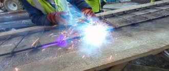
Cost reduction
For small household jobs, the cost of consumables for arc welding is relatively small. Therefore, an increase for any reason in the amount of materials spent changes little.
It’s a different matter when it comes to welding work at a large construction site or repair shop. Here, overspending in a fraction of a percent turns into thousands of losses.
Measures aimed at reducing costs during welding work are carried out in the following areas:
- Staff development
- The quality of welding equipment, its timely maintenance, repair and adjustment if necessary.
- Improving the quality of materials used and preparation of joints.
- Using new technologies, replacing, where possible, manual welding with automatic and semi-automatic ones.
Streltsov V., a welder with 22 years of experience: “An experienced welder, even with the worst equipment, uses less raw electrodes than a beginner. Of course, this does not exclude the need to adhere to technology.”
Calculation of overlapped joints
When making calculations, it is important to take into account the spatial position and type of welded joint. After all, when overlapping welding, the joints can be corner, flank, or frontal. Calculations make it possible to obtain data on the minimum permissible cross-sectional area and the design strength of the contact line. When calculating the area of a welded joint, the smallest height of a conditional triangular joint is taken as the basis. For manual welding, provided that the legs are equal, this coefficient will be 0.7.
If welding work is performed by automatic or semi-automatic machines, the depth of heating of the material will be greater. Therefore, indicators should be taken in reference tables.
Pipe calculator online
The pipe calculator allows you to perform online calculations of the parameters of the pipeline and individual elements: using the tools, you can calculate the weight of metal pipes (round, profile), diameter, throughput and cross-sectional area, volume and speed of the medium inside the system, pressure loss along the length and resistance coefficient (hydraulic calculation). Theoretical justifications for calculation methods are presented on the pages of individual calculators. To get the required result, go to the appropriate page, fill out the application fields and click the “ Calculate ” button.
Related regulatory documents:
- SP 31.13330.2012 “Water supply. External networks and structures"
- SP 30.13330.2016 “Internal water supply and sewerage of buildings”
- SP 60.13330.2016 “Heating, ventilation and air conditioning”
- GOST 10705-80 “Electric-welded steel pipes”
- GOST 380-2005 “Ordinary quality carbon steel”
- GOST 1050-88 “Carbon high-quality structural steel”
- GOST 4543-71 “Rolled products from alloy structural steel”
- GOST 5632-72 “High-alloy steels and corrosion-resistant, heat-resistant and heat-resistant alloys”
Source
Methodology for calculating welded joints
Welding is the simplest method of joining metal workpieces that exists today. The technology makes it possible to obtain strong and reliable connections. It is in demand in the creation of metal structures of various levels of complexity, in pipeline laying, construction, mechanical engineering and other industries. The characteristics of welded joints depend on many factors. The most significant of them are: thickness of workpieces, work conditions, consumables, equipment, metal composition. To first determine how strong the connection will be, you need to calculate the weld.
It is usually done during the design process and allows you to choose the right materials to perform a specific type of operation. Preliminary calculations are necessary in order to achieve the required safety margin of the structure. In this way, the required degree of reliability of finished products is achieved.