Feed rate
It is limited by the forces that act during cutting. These forces can lead to some malfunctions:
- fracture or change in the shape of the cutting element;
- deformation or breakage of the processed material;
- failure of the machine.
It is best to work at the highest feed value. Most often, this value is taken from special tables and manuals. They are compiled thanks to numerous studies and experiments carried out at machine-building plants. For 47 years now, the best guide has been the book by Yu.V. Baranovsky “Metal cutting modes” 1972. Over the years, it has been used by engineers at factories, teachers, and students at institutes. The manual takes into account the results of experimental studies of machining and metalworking production at the Volzhsky Automobile Plant.
When choosing a feed speed from reference material, this value is changed according to the kinematic parameters of the equipment on which metalworking is performed. Those. you need to take the nearest smallest feed value. For a rough pass, take a speed from 0.4 to 1.5 mm per revolution, for a finishing pass from 0.11 to 0.4 mm per revolution.
If you reduce the feed rate and increase the depth, the load on the equipment increases. If you do the opposite, the load will decrease. From this it turns out that depth has the greatest impact on equipment.
Aluminum turning: problems and their solutions
Aluminum is a fairly malleable material in terms of processing.
It can be sharpened at high speed. However, there are also peculiarities in cutting. With aluminum there are two key problems that can be encountered during processing. This is a high viscosity of the material, as well as a tendency to stick. These features must be taken into account when choosing a processing tool and cutting modes.
Let's start with the increased viscosity of the metal
. Pure aluminum and soft wrought aluminum alloys during processing form very long chips, which tend to wrap around the tool and clog the chip flutes. This often leads to the instrument overheating or breaking.
This feature forces us to take special measures to eliminate negative consequences. In particular, the cutting edges on the inserts must be as sharp as possible. For better chip removal, it is necessary to use coolant.
If aluminum contains a large admixture of silicon (over 13%), then you will not have any problems with eliminating chips - they are much shorter and can be easily removed. However, for turning high-strength aluminum alloys, it is preferable to use diamond-coated inserts.
The second feature that must be taken into account when cutting aluminum is its tendency to stick.
on the cutting edge of the tool. The edge becomes dull, causing increased stress on the tool. As a consequence, poor processing quality, the formation of build-up on the tool and in the cutting zone, an increase in temperature, leading to overheating and jamming of the tool.
Negative consequences can be avoided by installing a more productive operating mode, because low cutting speed only makes the problem worse. It is also necessary to choose the smoothest possible tool designed for turning aluminum and its alloys.
The TIGROTECH company offers the best inserts for processing non-ferrous metals from the American manufacturer Kennametal. Easy choice for various tasks.
The TIGROTECH company openly displays prices and delivery times for SMW-Autoblok driven tools.
You can find them in our catalog in our catalog.
Source
Cutting speed
This is the speed of movement of the cutting side of the cutter or metal in the direction of the main cutting movement. Denoted by the Latin letter V, measured in m/min. and is defined as follows:
V= π*d*n/1000 (1)
V is the cutting speed,
d – diameter of the processed material, measured in millimeters,
n – number of spindle revolutions per minute.
Knowing the value of V, you can obtain the required number of spindle revolutions. Having received this value, the required number of spindle revolutions is taken from the machine passport, which is closest to the value determined by the calculation method. If there is no passport, then take the theoretical number, i.e. the one obtained from the calculations. In this case, it is necessary to take into account the denominator of the progression, and not change the number of revolutions if the difference in diameters is insignificant.
The cutting speed can be obtained using formulas that are determined for all types of metalworking from indicators of tool life.
If it is necessary to perform longitudinal or transverse turnings, then the value of V will be:
V= Cv*Kv/T*t*S (2)
T – tool life period,
t – metal cutting depth,
S – feed speed.
Cv in this case is the coefficient obtained from observation during experiments. This value must be taken from the table of the special manual. The option for “standard” metalworking conditions is selected. The word “standard” conditions means the use of a pressure of 750 MPa and the use of a carbide cutter.
In real conditions, cutting and processing performance quite often does not coincide with “standard conditions”. For this reason, to obtain the optimal value, a correction factor is introduced - Kv. It takes into account all the differences.
It can be calculated as follows:
Kv=Kмv*Kпv*Kиv (3)
- Kmv – coefficient takes into account the influence of the workpiece metal;
- Kпv – value that takes into account the condition of the surface of the metal being processed;
- Kiv – coefficient takes into account the influence of the material from which the cutter is made.
All indicators are taken from reference books.
When cutting grooves or shaped turning, formula (2) is taken in a modified form. It does not take into account the value of t. Those. the formula will take the form:
V= Cv*Kv/T*S (4)
The speed that was calculated using formulas (2) and (4) is an estimate and the resulting value is only a recommendation.
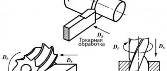
Process Features
Turning is carried out on special machines using cutters. The main movements are performed by the spindle, which ensures the rotation of the object attached to it. The feed movements are performed by a tool that is fixed in the support.
The main types of characteristic work include: face and shaped turning, boring, processing of recesses and grooves, trimming and cutting, thread design. Each of them is accompanied by productive movements of the corresponding equipment: passing and thrust, shaped, boring, trimming, cutting and threading cutters. A variety of types of machines allow you to process small and very large objects, internal and external surfaces, flat and volumetric workpieces.
Changing cutting speed
The cutting speed in metalworking depends on:
- Material, shape, properties of the cutting tool.
- Type of equipment. Lathes, milling machines, etc.
- Workpiece characteristics. For example, steel, what is its tensile strength.
- Cutting depths.
- Type of processing. Turning, thread cutting.
- Reliability and rigidity of workpiece fastening.
- Power and properties of equipment.
- The nature of metalworking.
The cutting speed that is allowed by the cutting element is influenced by various nuances: the durability of the cutter, the physical properties of the workpiece, the quantity and quality of the coolant, the permitted and permissible wear of the cutter.
The higher the speed of movement when cutting, the faster the durability of the cutters decreases. Suitable value for cutting tools from 25 to 55 m/min. If hard alloy plates are installed on the cutters, then this figure can be increased to 75-145 m/min. In this case, their durability will be from half an hour to an hour.
Which cutting tool to use
The production of parts on such machines is carried out using special turning tools. They must provide the following:
Types and purposes of turning tools
- high-quality processing of parts to obtain the desired shape and size;
- achieving high quality of the processed surface;
- high productivity with minimal energy costs;
- manufacturability in manufacturing;
- maintainability;
- minimal consumption of expensive materials for their production.
Turning cutters are classified according to different parameters. Depending on the type of work performed, they can be cutting, passing, shaped, scoring, etc. Cutters are made from various materials - diamonds, tungsten, titanium-tungsten and others. Depending on the design, these tools can be one-piece, prefabricated or combined.
The choice of a specific type of tool is carried out taking into account the modes of the work operations being carried out, the hardness of the workpiece, the geometric parameters of the cutting part and other characteristics.
Related video: Metal turning
Useful articles
Recommendations for cutting metal with a cutting torch
What is the largest lake in the world
Metal processing companies in Nizhny Tagil
Selecting cutting modes
To select a cutting mode, it is necessary to correctly select its main elements, that is, to determine and take into account the most favorable indicators of the values of these modes:
- Obtaining a technologically permitted feed rate. This is necessary to use all the power of the machine.
- Obtaining economical cutting speed. Helps to rationally use cutting elements.
After miscalculations, it is necessary to carry out checks using formulas or tables. They make it clear how the selected elements correspond to the power of the machine on which the metal will be cut, and the power of its drive is also determined. Checks are especially necessary if rough wiping work needs to be done.
Characteristics of operating modes
The calculation of the cutting operation is carried out using special reference and regulatory documents, of which there are quite a few at the moment. It is necessary to carefully study the tables presented and select the appropriate values in them. A correctly performed calculation guarantees the high efficiency of the applied part processing mode and ensures the achievement of the best result.
Main types of metal turning work
But this method of calculation is not always successful, especially in production conditions, when it is inappropriate to spend a lot of time studying tables with a huge number of values. It has been established that all values of cutting modes are interrelated. If you change one value, it is natural that all other processing characteristics will become different.
Therefore, very often specialists prefer to use calculation or analytical methods for determining cutting conditions. Special empirical formulas are used to determine all the necessary standards. In order for the calculations using this method to be absolutely accurate, you need to know the following parameters of the lathe:
- spindle speed;
- feed amounts;
- power.
In modern industries, special software is used to perform such calculations. The specialist just needs to enter the known data, after which the computer will produce the calculated values. The use of calculation programs greatly facilitates the work of specialists and makes production more efficient.
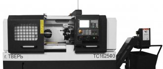
Lathe device
Graphic-analytical and machine methods
The graphical method is auxiliary and is based on mathematical calculations. The calculated feed results are plotted on a graph, where the lines of the machine and cutter are drawn and additional elements are determined from them. This method is a very complex complex procedure, which is inconvenient for mass production.
The machine method is an accurate and affordable option for experienced and novice turners, designed to calculate cutting conditions during turning. The program provides the most accurate values in accordance with the specified initial data. They must include:
- Coefficients characterizing the material of the workpiece.
- Indicators corresponding to the characteristics of tool metal.
- Geometric parameters of turning tools.
- Numerical description of the machine and methods of securing the workpiece on it.
- Parametric properties of the processed object.
Difficulties may arise at the stage of numerical description of the source data. By setting them correctly, you can quickly obtain a comprehensive and accurate calculation of cutting conditions during turning. The program may contain inaccuracies, but they are less significant than with the manual mathematical version.
The cutting mode during turning is an important calculated characteristic that determines its results. Tools and cooling and lubricants are selected simultaneously with the elements. A complete rational selection of this complex is an indicator of the specialist’s experience or perseverance.
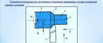
The main elements of the cutting mode include depth, feed and cutting speed. Let's consider the cutting scheme for turning using the example of turning a cylindrical surface on a lathe.
Turning efficiency criteria
Parts manufactured using turning are most often components of critical mechanisms. The requirements are met taking into account three main criteria. The most important thing is to do each of them as much as possible.
- Correspondence between the materials of the cutter and the object being turned.
- Optimization of feed, speed and depth among themselves, maximum productivity and quality of finishing: minimal roughness, precision of shape, absence of defects.
- Minimum resource costs.
The procedure for calculating the cutting mode during turning is carried out with high accuracy. There are several different systems for this.
Example
For certain processing conditions on a screw-cutting lathe model IK62, we determine the values of the theoretical cutting speed Vt:
- – when turning with a through cutter equipped with a soldered plate made of VK8 hard alloy
- , m/min;
- – when turning with a cutter equipped with a brazed plate made of P18 hard alloy
- , m/min.
The values of Сv = 5640 and 1500, m = 0.8, Хv = 0.55 and Уv = 0.55 were taken from reference normative materials on cutting.
It should be noted that the cutting speed does not have a significant effect on the roughness as does the feed value.
Using the passport data of the IK62 machine, we determine the actual cutting speed Vd.
Estimated spindle speed
, pr (for Vt = 120 m/min):
On the machine, Vt is the theoretical cutting speed for given processing conditions, m/min; Dз – workpiece diameter, mm.
Machine processing time
determined by the formula
where l is the length of the workpiece, mm;
l2 – overtravel length, according to standard tables: for depth of cut
where d is the diameter of the treated surface;
l1 – infeed length
where φ is the main angle in the plan of the cutter, we will take it equal to 60°.
S – longitudinal feed of the cutter per revolution of the workpiece. We replace the theoretical feed value S = 0.6 mm/rev with the value of the nearest feed available on the IK62 machine, i.e. S = 0.61 mm/rev.
The power Nр spent on the cutting process, with a cutting force Рz = 300 kg, is determined by the formula
Required motor power to perform a given processing mode
where η is the coefficient of performance (efficiency) equal to 0.75.
The load factor of the IK62 machine for the specified processing, with the power of its electric motor Nst = 10 kW.
The parameters of the cutting process include the main (technological) processing time - the time spent directly on the process of changing the shape, size and roughness of the workpiece surface being processed.
When turning a cylindrical surface, the main (machine) time and elements of the cutting mode are related by the relationship
where Li = l + l1 + l2 – path of the cutting tool relative to the workpiece in the feed direction ( l – length of the machined surface, mm; l1 = t·ctgφ – amount of cutter penetration, mm; l2 = 1–3 mm cutter exit (overtravel)) , i =H/t number of working strokes of the cutter required to remove the material left for processing (H – thickness of the removed metal layer, mm).
In general, piece time consists
where Tv is the auxiliary time necessary to perform actions related to preparation for the cutting process (approach and removal of tools, installation and removal of the workpiece, etc.);
Tob – time for servicing the workplace, equipment and tools in working condition;
Тп – time for rest and natural needs, allocated to one detail.
2.2. Selection of rational cutting modes when turning
The elements of the cutting mode are: depth of cut, feed and cutting speed.
Depth of cut t (mm) – the distance between the machined and machined surfaces, measured normal to the latter. When turning, this is the thickness of the metal layer cut in one cutter pass. When turning, boring, drilling
where D is the largest diameter of contact between the tool and the workpiece, mm; d – smallest diameter of contact between the tool and the workpiece, mm.
When drilling t = D / 2,
where D is the hole diameter, mm.
When cutting and turning a groove, the depth of cut corresponds to the width of the slot, performed by the cutter in one pass. Feed (mm/rev) – the amount of movement of the tool per revolution of the workpiece. There are longitudinal, transverse and inclined feeds depending on the direction of movement of the cutter. It is recommended to select the maximum possible feed rate for these processing conditions.
Cutting speed V (m/min) is the path traveled by the point of the cutting surface most distant from the axis of rotation relative to the cutting edge in the direction of the main movement per unit time. The cutting speed for machines with main rotational motion (lathes, drilling, milling) is calculated using the formula
V = p Dn / 1000 » Dn / 320,
where D is the largest diameter of the workpiece (during turning),
drill diameter (when drilling) or cutter diameter (when milling), mm;
n – workpiece or tool rotation speed, rpm.
The cutting mode, which ensures the fullest use of the cutting properties of the tool and the capabilities of the machine, subject to obtaining the required processing quality, is called rational.
To increase labor productivity, it is recommended to work with the highest cutting speed possible. However, its increase is limited by the durability of the tool, the rigidity and strength of the workpiece, machine components and its power.
High productivity can be achieved if, first of all, the highest possible values of cutting depth and feed are taken and, depending on them, the permissible cutting speed, ensuring the accepted tool life.
The cutting mode is selected based on the initial data: drawing of the workpiece, dimensions of the workpiece, type, material and geometry of the tool, passport data of the machine in the following order.
Read also: How to check a photoresistor with a multimeter
1. The depth of cut is taken depending on the amount of allowance. It is recommended to process in one pass. The minimum number of passes is determined by the power of the machine, the rigidity of the part and the specified processing accuracy. During roughing (if conditions allow), the depth of cut is set to the maximum - equal to the entire allowance. Precision surfaces are first pre-treated, then finally processed. During finishing processing, the cutting depth is assigned depending on the required degree of accuracy and surface roughness within the following limits: for surface roughness up to R z from 10 to 20 inclusive, cutting depth is 0.5 - 2.0 mm, for R z from 2.5 to 0.063 – 0.1 – 0.4 mm.
2. Feed is selected from standard tables depending on the type of material being processed, the size of the workpiece and the selected cutting depth. It is recommended to select the maximum possible feed rate for these processing conditions. During roughing, its value is limited by the rigidity of the part, the tool and the permissible force of the machine's safety feed mechanism. The finishing feed rate is determined mainly by the roughness of the machined surface. To reduce roughness, the feed should be taken less.
Finally, the feed is adjusted based on the machine data and the closest one available on the machine is adopted.
3. The cutting speed allowed by the tool is determined by the specified tool life, depth of cut, feed, hardness of the material being processed and a number of other factors. The average tool life is usually assumed to be 30–90 minutes.
The cutting speed is assigned according to the corresponding regulatory tables, depending on the properties of the material being processed, the accepted values of cutting depth and feed. Such tables are compiled for specific operating conditions. Therefore, if the actual cutting conditions differ from the standard ones, the selected speed must be multiplied by the correction factors attached to the tables.
4. Knowing the cutting speed, determine the rotation speed n (rpm) from the formula
n = 1000V/p D » 320V/D,
where V – cutting speed, m/min; D – largest diameter of contact between the tool and the workpiece, mm.
Since the machine may not have exactly the same spindle rotation speed due to its stepwise regulation, the nearest smaller value is assigned. As a result, the cutting speed is slightly reduced, but the durability of the cutting tool is increased.
5. Based on the accepted rotation speed, the actual cutting speed (m/min) is calculated.
6. Checking the cutting mode for power during rough turning can be done using the formula
where V – cutting speed, m/min; 1020 – conversion factor N x m/s to kW; P z – vertical component of the cutting force, N.
The vertical component of the cutting force P z (N) is the cutting resistance force acting in the vertical direction tangential to the cutting surface. For approximate calculations, it can be determined from the formula
where K is the cutting coefficient equal to the cutting force per 1 mm 2 of the cross-sectional area of the cut chips, MPa (Table 11);
t – cutting depth, mm; S – feed, mm/rev.
Average value of cutting coefficient K during turning
After calculating the cutting power, the condition must be met
where N cut is the power required for cutting; N sp – power on the spindle.
Example. Select cutting modes for turning a shaft made of steel 45 (s in = 650 MPa) with the following data: workpiece diameter D = 45 mm, part diameter d = 40-0.05 mm, length of the machined surface L = 200 mm, roughness Ra = 2 .5 µm, mounted in chuck and rear center.
Screw-cutting lathe 1K62; cutter – continuous thrust cutter with a plate made of hard alloy T15K6.
Cutter geometry: g = 12°, a = 10°, j = 90°, r = 1 mm; the shape of the front surface is flat with a positive front angle.
Solution. Given the high accuracy and low surface roughness of the part, turning should be performed in two passes. An allowance of 1 mm per diameter is left for finishing turning.
We assign the cutting mode for the rough transition.
1. Depth of cut
t = (D – d) / 2 = (45 – 41) / 2 = 2 mm.
2. From table. 20 choose a feed equal to S = 0.5 mm/rev.
3. According to table. 27 choose cutting speed V = 166 m/min.
According to the table 28 we set correction factors for the given operating conditions: K1 = 1; K2 = 1.15; K3 = 1; K4 = 1; K5 = 0.8.
We multiply the table speed by correction factors:
V = 166 * 1.15 * 0.8 = 152 m/min.
4. Determine the required rotation speed of the workpiece
n = 320 * V / D = 320 * 152 / 45 = 1080 rpm.
According to the machine passport table. 31 we take the nearest lower rotation speed n = 1000 rpm.
5. We clarify the actual cutting speed
V = Dn / 320 = 45 * 1000 / 320 = 140 m/min.
6. Check the power cutting mode on the machine spindle. We calculate the cutting force: P z = KtS.
From the table 11 cutting coefficient K = 1780 MPa, then
P z = 1780 * 2 * 0.5 = 1780 N.
Power required for cutting
N res = P z V / 60 * 1020 = 1780 * 140 / 60 * 1020 = 4.1 kW.
From the table 14 machine engine power N motor = 10 kW.
The machine efficiency is assumed to be h = 0.75. Then the power on the spindle will be
N sp = N dv h = 10 * 0.75 = 7.5 kW,
which is quite sufficient to implement the selected cutting mode.
We assign a cutting mode for finishing transition.
1. Depth of cut
t = (41 – 40) / 2 = 0.5 mm.
2. Feed (Table 21) S = 0.2 mm/rev.
3. Cutting speed from table. 27 is 235 m/min.
We adjust the cutting speed according to the changed operating conditions:
n = 235 * 1.15 * 0.8 = 216 m/min.
4. Determine the rotation speed of the workpiece:
n = 320 V / D = 320 * 216 / 41 = 1680 rpm.
Based on the machine data (Table 31), we take n = 1600 rpm.
5. Actual cutting speed
V = Dn / 320 = 41 * 1600 / 320 = 205 m/min.
Initial data
From the point of view of a systems approach, the turning process can be considered as the coordinated functioning of the elements of a complex system. These include: lathe, tool, workpiece, human factor. Thus, the effectiveness of this system is influenced by a list of factors. Each of them is taken into account when it is necessary to calculate the cutting mode during turning:
- Parametric characteristics of the equipment, its power, type of spindle rotation control (stepped or stepless).
- Method of fastening the workpiece (using a faceplate, faceplate and steady rest, two steady rests).
- Physical and mechanical properties of the processed metal. Its thermal conductivity, hardness and strength, the type of chips produced and the nature of its behavior relative to the equipment are taken into account.
- Geometric and mechanical features of the cutter: dimensions of the corners, holder, apex radius, size, type and material of the cutting edge with the corresponding thermal conductivity and heat capacity, toughness, hardness, strength.
- Specified surface parameters, including its roughness and quality.
If all the characteristics of the system are taken into account and rationally calculated, it becomes possible to achieve maximum efficiency of its operation.
Table method
The essence of this option is that the indicators of the elements are in the normative tables in accordance with the source data. There is a list of reference books that provide feed values depending on the parametric characteristics of the tool and workpiece, cutter geometry, and specified surface quality indicators. There are separate standards that contain maximum permissible limits for various materials. The starting coefficients necessary for calculating speeds are also contained in special tables.
This technique is used separately or simultaneously with the analytical one. It is convenient and precise to use for simple mass production of parts, in individual workshops and at home. It allows you to operate with digital values using a minimum of effort and initial indicators.