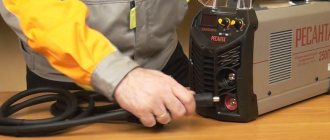
First of all, you must understand that different types of connections may be used in different conditions.
And their choice depends on the specific task at hand. For example, it is much more convenient to connect small-section wires up to 2.5 mm2 in a compact junction box with terminal blocks or clamps. But if we are talking about a groove or a cable channel, then the sleeves come first.
Let's consider the three most simple and at the same time reliable types of connections.
Existing methods of connecting conductors
Basic methods of connecting conductors in a house or apartment
Connecting wires can be done in several ways:
- welding is the most reliable method, ensuring high reliability of the connection, but requiring skills and the presence of a welding machine;
- terminal blocks - a simple and fairly reliable connection;
- soldering - works well if the currents do not exceed the norm and the connection does not heat up to temperatures above the norm (65°C);
- crimping with sleeves - requires knowledge of technology, special pliers, but the connection is reliable;
- use of spring clamps - wago, PPE - are quickly installed and, subject to operating conditions, ensure good contact;
- bolted connection - easy to perform, usually used in difficult cases - when it is necessary to switch from aluminum to copper and vice versa.
The specific type of connection is selected based on many factors. It is necessary to take into account the material of the conductor, its cross-section, the number of cores, the type of insulation, the number of conductors that will be connected, as well as operating conditions. Based on these factors, we will consider each type of connection.
Modern technologies
In many cases, the methods discussed are gradually becoming a thing of the past. They were replaced by factory wire connectors, which made installation and switching work much easier and faster:
- Terminal blocks, inside of which there are tubular brass sleeves. Stripped wire strands are inserted into these tubes and secured by tightening the screws.
- PPE caps, inside of which there are compression springs. The cores are inserted into the cap and then turned clockwise with little effort, thereby reliably compressing the connected wires inside.
- Self-clamping terminals. It is enough to place the wiring in them, and there it is automatically fixed due to the pressure plate.
- Lever-type terminal blocks. This connecting element is reusable. It is enough just to lift the lever, insert the conductor into the contact hole and lower the lever back, reliable fixation is ensured.
We do not talk in detail about all existing terminal blocks, since there is a separate article about this, where each type of wire clamp is discussed in detail.
We hope that we have clearly explained to you how to connect the wires correctly. Choose the method that suits you best. When choosing, take into account the cross-section and material of the conductors, the location of the connection (outdoors or indoors), and the amount of load current that will flow in this electrical circuit.
Welding – high reliability in any conditions
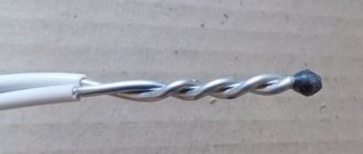
When connecting wires by welding, the conductors are twisted and their ends are welded. As a result, a metal ball is formed, which provides a stable and very reliable connection in any conditions. Moreover, it is reliable not only in terms of electrical characteristics, but also mechanically - the metal of the connected wires after melting forms a monolith and it is impossible to isolate a separate conductor.
Welding - it is important to heat the metal, but not melt the insulation
The disadvantage of this type of wire connection is that the connection is 100% permanent. If you need to change something, you need to cut off the fused piece and do it all over again. Therefore, for such connections, a certain supply of wires is left in case of possible alterations.
Other disadvantages include the need for a welding machine, appropriate electrodes, flux and operating skills. In addition, welding takes a lot of time, it is necessary to protect surrounding objects, and it is also inconvenient to work with a welder at height. Therefore, electricians practice this type of connection in exceptional cases. If you are doing it “for yourself” and know how to handle a welding machine well, you can practice on scraps. The main trick is to not melt the insulation, but to weld the metal.
After cooling, the welding site is isolated. You can use electrical tape, you can use heat shrink tubing.
Plug crimp connectors
These connectors use the same crimping and insulating tools as spade terminals, butt connectors (such as the Phoenix Contact 3240061 connector) are often found in the same manufacturer series as automotive terminals.
This connector is simply a metal tube (sometimes insulated) in which the stripped end of one wire is placed at one end of the tube, crimped, and repeated for the other wire on the other side.
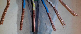
Connecting wires by crimping
To crimp wires, a special aluminum or copper sleeve is required - it is selected based on the size of the twist (bundle diameter), and the material is the same as for the conductors. The bare wires, stripped to a shine, are twisted, a tube-sleeve is put on them, which is clamped with special pliers.
An example of crimping conductors with a sleeve
Both sleeves and pliers are different, there are several types. Each of them has its own rules of use (the number of wires that can be packed in a sleeve), which you need to be well versed in. It is necessary to pack the wires according to certain rules, measure the size of the resulting bundle, and adjust it to the requirements. In general, a rather dreary task. Therefore, this type of wire connection is mainly used by professional electricians, and more and more often they are switching to spring clamps.
Welding
In order for the connection of electrical wires to be as reliable as possible, the considered twisting method must be subsequently secured by welding. It is similar to soldering, only now a welding machine is used instead of a soldering iron.
Positive sides
This method is most preferable to all others, since it meets all regulatory requirements in terms of reliability and quality.
The welding method is based on contact heating of the ends of the wires with a carbon electrode until a ball (contact point) is formed. This ball is obtained as a single unit from the fused ends of all connected cores, which ensures safe and reliable contact; it will not weaken or oxidize over time.
Negative sides
The disadvantage of welding is that such work requires certain knowledge, experience, skills and special equipment; you often have to turn to specialists.
Installation
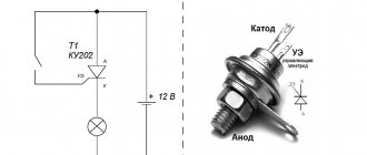
In order to connect wires using welding, you will need the following devices, tools and materials:
- welding inverter with a power of at least 1 kW, its output voltage must be up to 24 V;
- carbon or graphite electrode;
- goggles or eye mask;
- welding leather gloves to protect hands;
- a mechanic's knife or stripper for removing the insulating layer from conductors;
- sandpaper (for cleaning the conductive surfaces to be connected);
- insulating tape for further insulation of the welding joint.
The sequence of work is as follows:
- Free each connected wire from 60-70 mm of insulation.
- Sand the exposed wires until they are shiny using sandpaper.
- Twist, after biting, the length of its ends should be at least 50 mm.
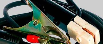
- Attach grounding clamps to the top of the twist.
- To ignite the arc, bring the electrode to the bottom of the twist and lightly touch the connected wires with it. Welding happens very quickly.
- It turns out to be a contact ball, give it time to cool, and then insulate it with tape.
As a result, an almost solid wire is obtained at the end, that is, the contact will have the lowest transition resistance.
If you connect copper wires in this way, then choose a carbon-copper electrode.
I would like to recommend that if you purchase a welding machine (it will be useful not only for connecting wires, but also for many other purposes), then choose the inverter option. With small dimensions, weight and electrical energy consumption, it has a wide range of welding current adjustment and produces a stable welding arc. And this is very important to be able to regulate the welding current. If you choose it correctly, the electrode will not stick and the arc will hold steady.
Watch how welding is done in this video:
We looked at the main types of wire connections. Now let’s briefly talk about methods that are used less frequently, but also guarantee quality and reliability.
Terminal blocks
One of the simplest and most reliable wire connections is through terminal blocks. There are several types, but almost all of them use a screw connection. There are sockets of different sizes - for different sizes of conductors, with different numbers of pairs - from 2 to 20 or more.
The terminal block itself is a plastic case in which a metal socket or plate is sealed. A bare conductor is inserted into this socket or between the plates and clamped with a screw. After the screw is tightened, you need to give the conductor a good tug to make sure it is tightly clamped. Due to the fact that the connection points remain uninsulated, the terminal blocks are used in rooms with normal humidity.
The disadvantage of such a connection: due to the ductility of metals - especially aluminum - the contact weakens over time, which can lead to an increase in the degree of heating and accelerated oxidation, which again leads to a decrease in contact. In general, the connection of wires in screw terminal boxes must be tightened periodically.
Connecting wires in terminal blocks
Advantages - speed, simplicity, low cost, does not require any skills, except the ability to use a screwdriver. Another important advantage is that you can easily connect wires of different diameters, single-core and stranded, copper and aluminum. There is no direct contact, so there are no risks.
TV coaxial cable connection
It is possible to extend or splice a coaxial television cable in three ways: – TV extension, commercially available from 2 to 20 meters – using an adapter TV F socket - F socket; - soldering with a soldering iron.
You can familiarize yourself with step-by-step instructions for connecting a coaxial television cable by visiting a separate article on the site “Connecting a TV cable.”
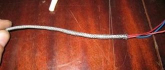
Connecting tinsel wire by twisting with a single-core or stranded conductor
If it is necessary to give the cord very high flexibility and at the same time greater durability, the wires are made using a special technology. Its essence lies in winding very thin copper ribbons onto a cotton thread. This kind of wire is called tinsel.
The name is borrowed from tailors. Gold tinsel is used to embroider the ceremonial uniforms of high-ranking military officers, coats of arms and much more. Copper tinsel wires are currently used in the production of high-quality products - headphones, landline phones, that is, when the cord is subjected to intense bending during use of the product.
In a cord of tinsel conductors, as a rule, there are several and they are twisted together. It is almost impossible to solder such a conductor. To attach tinsel to the contacts of products, the ends of the conductors are crimped into the terminals with a special tool. To make a reliable and mechanically strong twist connection without tools, you can use the following technology.
The insulation is removed from the 10-15 mm tinsel conductors and the conductors with which it is necessary to connect the tinsel to a length of 20-25 mm with a shift using a knife in the manner described in the site article “Preparing wires for installation.” The tinsel thread is not removed.
Then the wires and the cord are applied to each other, the tinsel is bent along the conductor and the wire core is tightly wound onto the tinsel pressed against the insulation. It is enough to make three to five revolutions. Next, the second conductor is twisted. You will get a fairly strong twist with a shift. Several turns of insulating tape are wound and the twisted connection of the tinsel to a single-core wire is ready. Thanks to shear twisting technology, the connections do not need to be separately insulated. If you have a heat-shrinkable or polyvinyl chloride tube of a suitable diameter, you can put on a piece of it instead of insulating tape.
If you want to get a straight connection, you need to rotate the single-core wire 180° before insulating it. The mechanical strength of the twist will be greater. The connection of two cords with tinsel-type conductors to each other is carried out using the technology described above, only for wrapping, a piece of copper wire with a diameter of about 0.3-0.5 mm is taken and at least 8 turns must be made.
Soldering
First, about soldering technology. The connected conductors are stripped of insulation, cleared of the oxide film to bare metal, twisted, and then tinned. To do this, the conductors are heated with a soldering iron and applied to rosin. It should cover the joint completely. Tinned wires are twisted first with your fingers, then pressed using pliers. Instead of tinning, you can use soldering flux. They wet the wires well, but after twisting.
Then, in fact, the soldering process begins: the joint is heated with a soldering iron or narrow torch. When rosin or flux begins to boil, take some of the solder onto the soldering iron tip and bring it into the soldering zone, pressing the tip against the conductors. The solder flows to fill the gaps between the wires, making a good connection. When using a torch, solder is simply added little by little into the torch.
Next, after the soldering area has cooled, according to the technology, it is necessary to wash off the remaining flux (they accelerate oxidation), dry the joint, cover it with a special protective varnish, and then insulate it with electrical tape and/or heat-shrinkable tubes.
Now about the advantages and disadvantages of this method of connecting wires. In low-current systems, soldering is one of the most reliable methods of connecting wires. But, when installing electrical wiring in a house or apartment, it is criticized mercilessly. The thing is that solder has a low melting point. When large currents periodically pass through the connection (this happens if the circuit breakers are incorrectly selected or faulty), the solder gradually melts and evaporates. Over and over again, the contact becomes worse and the connection heats up more and more. If this process is not detected, the matter may well end in a fire.
The second negative point is the low mechanical strength of soldering. It's the tin again - it's soft. If there are a lot of wires in a soldered joint, and if they are also rigid, when you try to pack them, the conductors often fall out of the solder joint - the elastic force is too great, which pulls them out. That is why it is not recommended to use soldering connections when wiring electricity: it is inconvenient, time-consuming and risky.
Twist
Let's start with the simplest and most well-known method - twisting. It can also be called the oldest; it’s not for nothing that electricians call twisting the “old-fashioned method.”
We will not tell you that such a connection of wires is durable and reliable. According to the main document in electrical engineering, PUE (“Rules for Electrical Installations”), twisting is generally prohibited, despite the fact that half a century ago it was used everywhere. The fact is that in those days the load in the apartments consisted only of lighting, radio or television. If you consider the current load in modern apartments with a huge amount of household appliances used daily, then no old insulation, core cross-sections and methods of connecting wires are any longer suitable.
Nevertheless, we will talk about twisting, and even first of all, because it is the main stage of such connection options as welding and soldering.
Positive sides
The most important advantage of twisting is that it requires absolutely no material costs. All you need is a knife to remove the insulating layer from the wire cores and pliers to make the connection.
The second indisputable advantage of twisting is its ease of execution. You don’t need any special knowledge or skills; it can be done by anyone who has ever held pliers in their hands.
Several wires can be connected simultaneously in a twist, but their total number should not exceed six.
Negative sides
The main disadvantage of twisting is its unreliability; it weakens over time. This is due to the fact that there is residual elastic deformation in the cable or wire cores. At the point of twisting, the contact resistance increases, which can lead to contact failure and heating. In the best case, you will detect this in time and re-seal the connection; in the worst case, a fire may occur.
Electrical wires made of different metals cannot be connected using twisting. As an exception, you can twist copper and aluminum wire, but only if the copper core is first tinned with solder.
In electrical engineering there are concepts of detachable or permanent connection. So twisting does not apply to one or the other. A detachable connection is characterized by the fact that its ends can be disconnected many times. This cannot be fully done in twisting; every time after the next unwinding and twisting of the cores, they will deteriorate. It is also impossible to call twisting a permanent connection, because it does not contain the concepts of strength, reliability and stability necessary for this. This is another disadvantage of the twist connection.
Installation
If for some reason you do not have the opportunity to use other methods of connecting electrical wires, you can use twisting, just do it well. Very often it is used as a temporary option and is subsequently replaced by more reliable switching methods.
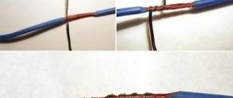
How to connect wires using twist? To begin with, the cores are stripped to 70-80 mm. The main thing is to twist all switched conductors into one single twist at the same time, and not wind one around the other.
Many people mistakenly begin to twist the wires together from the place where the insulating layer ends. But it is better in this place to clamp both wires with one pair of pliers, and with the other, grab the ends of the wires and perform rotational movements in a clockwise direction.
If the wire cross-section is small, you can twist it by hand. Align the conductors along the cut of the insulation and hold them firmly in this place with your left hand. Bend all switchable ends into one single bend at an angle of 90 degrees (a bend length of 10-15 mm will be enough). Hold this bend with your right hand and rotate clockwise. This must be done firmly and firmly. If it is already difficult to twist your hands at the end, use pliers as described above. As soon as the twist becomes smooth and beautiful, you can trim the bend.
You can connect several wires this way, but then to make it easier to twist them, make the bend longer, somewhere around 20-30 mm.
How to properly twist wires is shown in this video:
There is also a way to twist wires using a screwdriver, see about it here:
For information on twisting wires using a special tool, see here:
Now the resulting twist must be carefully insulated. Electrical tape is used for this. Do not spare it, wind it in several layers, and insulate not only the connection itself, but also step 2-3 cm over the core insulation. This way, you will ensure the insulating reliability of the twist and protect the contact connection from moisture.
You can also insulate the connection of wires using heat pipes. The main thing is not to forget to put the tube on one of the cores to be connected in advance, and then push it into the place where it is twisted. When exposed to heat, the thermal tube shrinks, so slightly heat its edges and it will firmly grip the wire, thereby providing reliable insulation.
If the twisting is done well, there is a chance that it will serve you for many years, provided that the load current in the network is normal. But it’s still better not to stop at this stage and strengthen the joint by welding or soldering.
Spring clamps for connecting wires
One of the most controversial ways to connect wires is using spring clamps. There are several types, but the two most common are wago terminal blocks and PPE caps. Externally and in terms of installation method, they are very different, but both designs are based on a spring, which creates strong contact with the wire.
There is controversy about this spring. Opponents of using wago say that the spring will weaken over time, the contact will become worse, the connection will begin to heat up more and more, which, again, leads to an even more rapid decrease in the degree of elasticity of the spring. After some time, the temperature may rise so much that the body (plastic) will melt, but what can happen next is known.
Spring clamps for electrical wiring - popular connections for wires
In defense of using spring clamps to connect wires, if they are used according to manufacturers' recommendations, problems are very, very rare. Although there are many fakes of both wago and PPE, as well as a sufficient number of photographs of them in melted form. But, at the same time, many people use them, and, under normal operating conditions, they work for years without complaints.
wago wire clamps
They appeared on our market several years ago and made a lot of noise: with their help, the connection is very quick and easy, and at the same time has high reliability. The manufacturer has specific recommendations for using this product:
- wago should only be used for single-core or stranded conductors with a cross-section from 0.5 mm2 to 4 mm2;
- to fix and connect stranded and small-diameter wires, use the CAGE CLAMP - from 0.08 mm2 to 35 mm2; What's inside wago wire clamps
Inside these devices there is a metal plate, which ensures the proper degree of contact. The shape and its parameters of the plates were specially developed and tested. The tests were carried out on a vibration stand for many hours, then heated and cooled. After which the electrical parameters of the connection were checked. All tests were passed “excellent” and branded products always perform “five”.
In general, the range of Wago products is very wide, but for installing electrical wiring or connecting home appliances and lighting fixtures, two types of wire clamps are used: series 222 (detachable) with the ability to reconnect or change the connection, and series 773 and 273 - which are called permanent.
Detachable
Spring clamps for electrical wiring Wago 222 series have a certain number of contact pads - from two to five - and the same number of locking flags. Before starting the connection, the flags are raised up, the conductors stripped of insulation are inserted into them (all the way), after which the flag is lowered. At this point the connection is considered complete.
Wago wire connectors - connection methods
If necessary, you can reconnect the connection - lift the locking flag and remove the conductor. Convenient, fast and reliable.
Wago 222 series range
The 222 Vago series can be used to connect two or three, even five conductors made of copper or aluminum (you can connect different metals in one terminal). Wires can be single-core or multi-core, but with rigid wires. The maximum cross-section is 2.5 mm2. Soft stranded wires can be connected with a cross-section from 0.08 mm2 to 4 mm2.
One-piece
There is another type of clamps that does not provide the ability to redo the connection of wires - series 773 and 273. When using these terminals, the work is generally done in seconds: the stripped wire is inserted into the appropriate socket. The spring present there clamps it, ensuring contact with the plate. All.
wago contact terminals
These spring loaded wire clamps can be used to connect solid aluminum or copper wires with cross-sectional area from 0.75 mm2 to 2.5 mm2, stranded wires with rigid wires from 1.5 mm2 to 2.5 mm2. Soft stranded conductors cannot be connected using such connectors.
Types of mounting terminals for wago wiring
To improve contact, the wires must be cleaned of oxide film before connecting. To prevent oxidation from continuing, wago manufacturers also produce contact paste. The inside of the clamp is filled with it and it itself corrodes the oxide film, and then protects the wires from oxidation in the future. In this case, only heavily oxidized, dark conductors need preliminary stripping, and the clamp body is filled with paste.
By the way, manufacturers say that, if desired, the wire can be pulled out of the clamp. To do this, grab the wire with one hand, hold the terminal box with the other and rotate them back and forth with a small range, in opposite directions, stretching them in different directions.
Clamps for lamps (construction and installation terminals for lamps)
For quick and convenient connection of lamps or sconces, wago has special 224 series terminals. With their help, you can connect aluminum or copper wires of different sections and types (single-core or stranded with rigid wires). The rated voltage of this connection is 400 V, rated current:
- for copper conductors - 24 A
- 16 A for aluminum.
Methods for connecting wires in chandeliers and sconces using wago clamps
Cross-section of connected conductors from the mounting side:
- copper 1.0 ÷ 2.5 mm2 – single-core;
- aluminum 2.5 mm2 – single-core.
Cross-section of connected conductors on the side of the chandelier/sconce: copper 0.5 ÷ 2.5 mm2 – single-core, stranded, tinned, crimped.
When connecting aluminum wires, it is necessary to use contact paste, and copper wires must be stripped by hand to bare metal.
This product has two disadvantages. The first is that the price of original terminals is high. Secondly, there are a lot of fakes at a lower price, but their quality is much lower and they burn and melt. Therefore, despite the high cost, it is better to buy original products.
PPE caps
PPE caps (which stands for “connector insulating clips”) are very easy to use devices. This is a plastic case, inside of which there is a spring that has a conical shape. The conductors, stripped of insulation, are inserted into the cap, and the cap is turned clockwise several times. You will feel that it has stopped scrolling, which means the connection is ready.
How to make a wire connection using PPE
These conductor connectors are produced by many manufacturers; they are available in different sizes, for different diameters and the number of connected conductors. In order for the wire connection to be reliable, the size must be selected correctly, and for this you need to understand the markings.
After the letters PPE there are several numbers. Depending on the manufacturer, the number of numbers varies, but they mean the same things. For example, there is this type of marking: SIZ-1 1.5-3.5 or SIZ-2 4.5-12. In this case, the number immediately following the letters indicates the type of case. “1” is set if the body is a regular cone, on the surface of which grooves can be applied for better grip. If there is a SIZ-2, then there are small protrusions on the body that are convenient to grasp with your fingers and twist.
All other numbers reflect the total cross-section of all conductors that can be connected using this particular PPE cap.
An example of marking of PPE caps and its explanation
For example, PPE-1 2.0-4.0. This means that the body of the connecting cap is ordinary, cone-shaped. With its help, you can connect two conductors with a cross section of at least 0.5 mm2 (in total they give 1 mm, which meets the minimum requirements - see the table). This cap contains a maximum of conductors whose total cross-section should not exceed 4 mm2.
Connecting wires using PPE caps
In the second version of marking, after the abbreviation PPE there is only a number from 1 to 5. In this case, you just need to remember which of them is useful for which cross-section of wires. The data is in another table.
PPE caps and their parameters
By the way, only copper wires can be connected with PPE caps - aluminum wires, as a rule, are thicker than the maximum allowable for these connectors.
Removing the insulating layer from the wires
I would like to immediately dwell on a question that will be common to any method. Before connecting the wires into a common electrical unit, they must be stripped of the top insulating layer.
This can be done using a mechanic's knife. This method is simple, but there is a high probability of damage to the conductor. To do everything correctly, you must strictly follow the step-by-step instructions:
- Place the wire on some flat surface (such as a table).
- Press it with your left index finger.
- With your right hand, take the knife and lightly press it into the insulating sheath of the wire. To avoid snagging the metal core, position it towards the cut at an angle. If the angle is right, there is a possibility of a circular cut in the core, as a result of which it may subsequently break.
- Hold the knife in this position. Using the index finger of your left hand, slowly twist the conductor one full turn, thus cutting the insulation around the entire circle.
- All that remains is to pull off the cut piece of insulation.
Professional electricians now necessarily have in their arsenal such a device as a stripper. This is a multifunctional tool that can be used to strip insulation from a wire or cut a cable. It can be simple, semi-automatic or automatic. The most important thing is that when stripping the insulation with a stripper, the conductor is not damaged. For each standard core diameter, such a tool has a calibrated hole with a cutting edge.
The length to which wire cores need to be stripped is different for each connection method.
Bolted connection
This connection is assembled from a bolt of any diameter, a suitable nut and one, or better yet, three washers. It is assembled quickly and easily, serves quite a long time and reliably.
Bolted wire connection
First, the conductors are stripped of insulation and, if necessary, the top oxidized layer is removed. Next, a loop is formed from the stripped part, the internal diameter of which is equal to the diameter of the bolt. To make it easier, you can wrap the wire around the bolt and tighten it (middle option in the right picture). Afterwards it all comes together in this order:
- A washer is placed on the bolt.
- One of the conductors.
- Second puck.
- Another conductor.
- Third puck.
- Screw.
The connection is tightened first with your hands, then with the help of keys (you can take pliers). That's all, the connection is ready. It is used mainly if it is necessary to make a connection between wires made of copper and aluminum; it can also be used when connecting conductors of different diameters.
Wago
The next type is Wago terminal blocks. They also come in different sizes, and for different numbers of connected wires - two, three, five, eight.
They can connect both monocores and stranded wires together.
For stranded ones, the clamp must have a latch-flag, which, when open, easily allows you to insert the wire and clamp it inside after latching.
According to the manufacturer, these terminal blocks in home wiring can easily withstand loads of up to 24A (lights, sockets).
There are some compact specimens also available for 32A-41A.
Here are the most popular types of Wago clamps, their markings, characteristics and what cross-section they are designed for:
There is also an industrial series for cable cross-sections up to 95mm2. Their terminals are really large, but the principle of operation is almost the same as that of small ones.
When you measure the load on such terminals, with a current value of more than 200A, and at the same time you see that nothing is burning or heating, many doubts about Wago products disappear.
If you have original Vago clamps, and not a Chinese counterfeit, and the line is protected by a circuit breaker with a correctly selected setting, then this type of connection can rightfully be called the simplest, most modern and convenient to install.
Violate any of the above conditions and the result will be quite natural.
Therefore, there is no need to install wago at 24A and at the same time protect such wiring with a 25A automatic. In this case, the contact will burn out if overloaded.
Always choose the right terminal blocks for your car.
As a rule, you already have automatic machines, and they primarily protect the electrical wiring, and not the load and the end consumer.
ZVI
There is also a fairly old type of connection, such as terminal blocks. ZVI – insulated screw clamp.
In appearance, this is a very simple screw connection of wires to each other. Again, it comes in different sections and different shapes.
Here are their technical characteristics (current, cross-section, dimensions, screw torque):
However, ZVI has a number of significant disadvantages, due to which it cannot be called the most successful and reliable connection.
Basically, you can only connect two wires to each other in this way. Unless, of course, you specifically choose large pads and shove several wires there. What to do is not recommended.
This screw connection works well for monocores, but not for stranded flexible wires.
For flexible wires, you will have to press them with NShVI lugs and incur additional costs.
You can find videos online where, as an experiment, transition resistances on different types of connections are measured with a microohmmeter.
Surprisingly, the lowest value is obtained for screw terminals.
How to connect aluminum and copper conductors
By the way, let us remind you why you cannot directly connect copper and aluminum wires. There are two reasons:
- This connection gets very hot, which in itself is very bad.
- Over time, the contact weakens. This happens because aluminum has a lower electrical conductivity than copper, and as a result, when the same currents pass through, it heats up more. When heated, it expands more, squeezing out the copper conductor - the connection becomes worse and gets hotter.
To avoid such troubles, copper and aluminum conductors are connected using:
- terminal blocks;
- wago;
- bolted connection;
- branch clamps (make connections of wires on the street).
Other types of connectors cannot be used.
Connectors for wires and cables
Connectors are special devices that facilitate the connection of two or more conductors. There are screw and clamping mechanisms.
Screw terminals
Used to connect wires of different materials and different diameters. An exception is multi-core electrical wires, which are crimped with special lugs. Also, screw clamps can damage aluminum wires, so it is better not to use them for such material.
Screw terminals
Allows you to connect aluminum and copper conductors together. They are easy to connect.
Power clamp
In such clamps, the stripped conductor is placed in the hole to the end. There it is automatically fixed by a pressure plate. Clamps can be used to secure copper and aluminum wires.
Clips
To install the wire, the clip clamp is placed in a vertical position, the wires are inserted inside, and then the clamp must be moved to a horizontal position. Plus, you can make adjustments.
Spring clamps
PPE caps are used as spring clips. Thanks to them, you can quickly make contact between two wires of similar diameters. It is important to choose the correct clamp, otherwise the contact will be unreliable.
Spring terminals
Wago spring terminals ensure reliable contact quickly and efficiently. However, over time, the spring may weaken or overheat.
Connection clamps
There are two types - electrical and electrical. The only difference is the current load. The connection takes place inside the device.
Couplings
It is made in the form of a metal tube. Used for conductors with a cross section of 0.25-16 mm. The wire is fixed by force crimping. Not used for single-core wires.
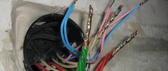
About the distribution box
In an apartment or house, wires from the electrical panel are routed to different rooms. There are usually several connection points: switch, sockets, and so on. In order for all the wires to be collected in one place, distribution boxes were created. They carry wiring from sockets, switches and are connected in a hollow housing.
So that during repairs you do not have to look for where the wires are hidden in the walls, electrical wiring is laid on the basis of special rules prescribed in the PUE (Electrical Installation Rules).
The main recommendation is that all connections are made in the junction box.
Distribution boxes are classified according to the type of fastening. So, there are boxes for external installation and internal installation. For the second option, you need to prepare a hole in the wall into which the box will be inserted. As a result, the box lid is located flush with the wall. Often the cover is hidden with wallpaper or plastic during repairs. As a last resort, an outer box is used, which is attached directly to the wall.
There are round or rectangular junction boxes. In any case, there will be at least 4 exits. Each outlet has a fitting or thread to which a corrugated tube is attached. This is done to quickly replace the wire. The old wire is pulled out and new wiring is laid. It is not recommended to lay the cable in a groove on the wall. If the electrical wiring burns out, you will have to dig into the wall and disturb the finish in order to carry out repair work.
Clamps for other purposes
In addition to the designs of clamps intended for connecting electrical conductors, there are a variety of similar accessories for other purposes.
Anchor clamps for fastening
Designs of clamps for fastening (suspension) of wires with a cross-section of 2 - 25 mm 2 in an amount of two to four wires. Structurally, the anchor accessory consists of a polymer body equipped with a self-adjusting clamping wedge.
A device whose design also assumes the role of a clamp. However, in this case we are no longer talking about connecting the conductors, but about the installation method - fixing it in a suspended state
Two configurations of anchor clamps are available:
- for self-supporting systems;
- under an isolated carrier neutral.
The mechanism has an easy-to-open bow, making it convenient and easy to install the clamp on brackets, hooks, and then attach electrical wires to the body of the clamp.
Wire clamps for test needs
Often the practice of electronics and electrical engineering involves the use of clamps for so-called “test” purposes. Traditionally, such accessories are “crocodiles” - jagged sliding (push) metal structures.
The toothed part of such a clamp remains open, while the pressure part is insulated with PVC material.
Another option for the design of clamping elements belonging to the class of equipment under test. So-called alligator clips are used to make a temporary contact, for example, to measure voltage
Such accessories are used for temporary attachment (engagement) to wires, for example, for the purpose of measuring current or network voltage.
This type of clamp can be divided into two categories - for low-voltage electronics and for high-voltage electrical networks. Both categories differ from each other in the limiting technical parameters for current.
Connecting wires easily
You can put the duty tape in the back drawer: you won’t need it anymore. Instead of this:
- We go to the nearest store and buy terminals (clamps). The asking price is 8–50 rubles. It is advisable to take WAGO 222 terminals with levers. As the electrician explained, they are the most reliable and easiest to use.
- We strip both wires to the depth of the terminal block, approximately 1 cm.
- We collect the strands of the stranded wire into a tight bundle and twist them slightly.
- Both conductors must be straight and clean.
- Raise the levers and insert both wires into the holes. We clamp by lowering the levers down.
Ready. With this connection method, you do not need to think about the quality of twisting and insulation. The length of the wiring remains the same. If necessary, the lever can be lifted and the wire removed - that is, the clamp is reusable.
The WAGO 222 clamp comes with 2 holes or more. It is designed for connecting single- and multi-core copper wires with a cross-sectional area of 0.08–4 mm, used in household electrical networks with voltages up to 380 V. Using the terminal block, lamps, electricity meters, garlands and much more are connected.
Types of terminal blocks
It is worth saying that terminal blocks are different:
- Screw terminals in polyethylene sheath. The most common, inexpensive and structurally simple. Inside the insulating shell there is a brass sleeve with two screws - they are used to screw the wires inserted into the holes on both sides. The downside is this: screw terminals are not suitable for aluminum conductors and stranded wires. Under constant pressure from the screw, the aluminum becomes fluid and the thin strands are destroyed.
- Screw terminal blocks with metal plates. More reliable design. The wires are clamped not with screws, but with two plates with characteristic notches. Due to the increased clamping surface, these terminals are suitable for stranded wires and aluminum.
- Self-clamping express terminal blocks. No less simple design, but much more convenient. It is enough to push the wire into the hole until it stops, and it will be securely clamped. Inside there is a miniature tinned copper shank and a fixing plate. Manufacturers also often place a paste inside - a mixture of technical petroleum jelly and quartz sand. It removes the oxide film from the surface of aluminum and subsequently prevents it from forming again.
To connect an aluminum wire to a copper wire (no matter how many wires they have), you need a special terminal block with paste. The fact is that copper and aluminum form a galvanic couple
When metals interact, the destruction process starts. The resistance at the connection point increases, as a result of which the structure begins to heat up. This often leads to melting of the insulation or, even worse, sparking. The higher the current, the faster the destruction occurs.
Why is it better to crimp (crimp) wires?
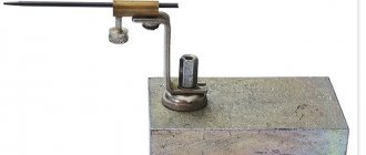
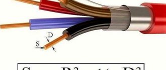
Wire crimping is one of the most reliable and high-quality methods of mechanical connections currently used. With this technology, loops of wires and cables are crimped into a connecting sleeve using press pliers, ensuring tight contact along the entire length.
The sleeve is a hollow tube and can be made independently. For liner sizes up to 120 mm², mechanical pliers are used. For large sections, products with a hydraulic punch are used.
When compressed, the sleeve usually takes the shape of a hexagon; sometimes local indentation is made in certain parts of the tube. In crimping, sleeves made of electrical copper GM and aluminum tubes GA are used. This method allows for crimping conductors made of different metals. This is largely facilitated by the treatment of the constituent components with quartz-vaseline lubricant, which prevents subsequent oxidation. For joint use, there are combined aluminum-copper sleeves or tinned copper sleeves GAM and GML. Wire connections using the crimp method are used for conductor bundles with a total cross-sectional diameter between 10 mm² and 3 cm².
Sleeves
When powerful clamps for several wires are needed, sleeves are used. They are a tinned copper tube or a flat tip with a hole made for fastening.
All connected wires must be inserted into the sleeve and crimped using a special crimper device (crimping pliers). This wire clamp has a number of positive aspects:
- It is very convenient to use lugs with holes when there is a need to secure wire assemblies to housings with screws.
- Crimping at the connection does not increase the resistance.
As you can see, there are a lot of wire clamps, each with its own advantages and disadvantages. Choose based on which wires you need to connect and where the connection will be located. But do not forget that the most important thing in electricity is reliability and safety.