Some requirements that this tool must meet
The selected countersink (according to GOST or reference books, or both) must comply with the following technical conditions of use:
— In products made of structural steel, holes with a diameter of up to 8 centimeters are bored using high-speed steel equipment. Its diameter should reach 32-80 mm. The equipment must have attachment heads.
— If the product is made of non-ferrous metals or cast iron, a feather tool is used to bore blind holes.
— If the product was made of hardened steel, which was difficult to process, you need to use a tool with carbide plates to stretch the holes in this part, their diameter is about 14 mm-5 cm. And the tool should have 3-4 teeth.
Conical countersinks GOST 14953-80, DIN 334, DIN 335 and DIN 347 | Gamma-Pro
| A countersink is a multi-blade cutting tool for machining cylindrical and conical holes in parts to increase their diameter, improve surface quality and accuracy. Working with a countersink is called countersinking. Countersinking is a semi-finish cutting process. In our company you can order delivery or production, and also, if available in stock, purchase Conical Countersinks GOST 14953-80: |
| Type 1 - countersinks with 60° centering angle | |||
| Countersink designation | |||
| 2353-0081 | 5 | 50 | 10 |
| 2353-0082 | 8 | 60 | 12 |
| Type 2 - centering countersinks for center holes with apex angle of 60° without safety cone | ||||
| Countersink designation | ||||
| 2353-0083 | 5,0 | 2,00 | 45 | 3,0 |
| 2353-0084 | 6,3 | 2,50 | 50 | 3,7 |
| 2353-0085 | 8,0 | 3,15 | 4,7 | |
| 2353-0086 | 10,0 | 4,00 | 56 | 6,0 |
| 2353-0087 | 12,5 | 5,00 | 63 | 7,4 |
| 2353-0088 | 16,0 | 6,30 | 71 | 9,5 |
| Type 3 - centering countersinks for center holes with an apex angle of 60° with a safety cone of 120° | |||||
| Countersink designation | |||||
| 2357-0001 | 0,80 | 5,0 | 1,55 | 35,5 | 0,82 |
| 2357-0002 | 1,00 | 6,3 | 2,00 | 1,13 | |
| 2357-0003 | 1,25 | 7,1 | 2,40 | 40,0 | 1,21 |
| 2357-0004 | 1,60 | 8,0 | 3,10 | 45,0 | 1,52 |
| 2357-0005 | 2,00 | 10,0 | 4,00 | 2,20 | |
| 2357-0006 | 2,50 | 12,5 | 5,00 | 50,0 | 2,60 |
| 2357-0007 | 3,15 | 14,0 | 6,40 | 3,30 | |
| 2357-0008 | 4,00 | 16,0 | 7,90 | 56,0 | 4,20 |
| 2357-0009 | 5,00 | 20,0 | 10,00 | 63,0 | 5,20 |
| 2357-0010 | 6,30 | 25,0 | 12,50 | 71,0 | 6,50 |
| Type 4 - centering countersinks for center holes with apex angle of 75° without safety cone | ||||
| Countersink designation | ||||
| 2353-0089 | 6,3 | 45 | 2,0 | 3,1 |
| 2353-0090 | 8,0 | 50 | 2,5 | 3,9 |
| Type 5 - countersinks with apex angle of 60° with a cylindrical shank; Type 6 - countersinks with an apex angle of 90° with a cylindrical shank; Type 7 - 120° countersinks with cylindrical shank | |||||||||
| Type 5 countersink designation | Type 6 countersink designation | Type 7 countersink designation | |||||||
| Type 5 | Types 6, 7 | Type 5 | Types 6, 7 | ||||||
| 2353-0101 | 8,0 | 1,6 | 8 | 48 | — | 16 | — | ||
| 2353-0107 | — | 44 | — | 12 | |||||
| 2353-0114 | |||||||||
| 2353-0102 | 10,0 | 2,0 | 50 | — | 18 | — | |||
| 2353-0108 | — | 46 | — | 14 | |||||
| 2353-0115 | |||||||||
| 2353-0103 | 12,5 | 2,5 | 52 | — | 20 | — | |||
| 2353-0109 | — | 48 | — | 16 | |||||
| 2353-0116 | |||||||||
| 2353-0104 | 16,0 | 3,2 | 10 | 60 | — | 24 | — | ||
| 2353-0111 | — | 56 | — | 20 | |||||
| 2353-0117 | |||||||||
| 2353-0105 | 20,0 | 4,0 | 64 | — | 28 | — | |||
| 2353-0112 | — | 60 | — | 24 | |||||
| 2353-0118 | |||||||||
| 2353-0106 | 25,0 | 7,0 | 69 | — | 33 | — | |||
| 2353-0113 | — | 65 | — | 29 | |||||
| 2353-0119 | |||||||||
| Type 8 - countersinks with apex angle of 60° with a tapered shank; Type 9 - countersinks with an apex angle of 75° with a tapered shank; Type 10 - countersinks with a 90° apex angle with a tapered shank; Type 11 - 120° countersinks with tapered shank | ||||||||||||
| Type 8 countersink designation | Type 9 countersink designation | Type 10 countersink designation | Designation for countersink type 11 | Morse cone | ||||||||
| Type 8 | Type 9 | Types 10, 11 | Type 8 | Type 9 | Types 10, 11 | |||||||
| 2353-0121 | 16,0 | 3,2 | 97 | — | — | 24 | — | — | 1 | |||
| 2353-0133 | — | 93 | — | 20 | ||||||||
| 2353-0142 | ||||||||||||
| 2353-0122 | 20,0 | 4,0 | 120 | — | 28 | — | 2 | |||||
| 2353-0134 | — | 116 | — | 24 | ||||||||
| 2353-0143 | ||||||||||||
| 2353-0123 | 25,0 | 7,0 | 125 | — | — | 33 | — | — | 2 | |||
| 2353-0135 | — | 121 | — | 29 | ||||||||
| 2353-0144 | ||||||||||||
| 2353-0124 | 31,5 | 9,0; 7,0* | 132 | — | — | 40 | — | — | ||||
| 2353-0129 | — | 127 | — | 35 | ||||||||
| 2353-0136 | — | 124 | — | 32 | ||||||||
| 2353-0145 | ||||||||||||
| 2353-0125 | 40,0 | 12,5; 11,0* | 160 | — | — | 45 | — | — | 3 | |||
| 2353-0131 | — | 155 | — | 40 | ||||||||
| 2353-0137 | — | 150 | — | 35 | ||||||||
| 2553-0146 | ||||||||||||
| 2353-0126 | 50,0 | 16,0 | 165 | — | — | 50 | — | — | ||||
| 2353-0138 | — | 153 | — | 38 | ||||||||
| 2353-0147 | ||||||||||||
| 2353-0127 | 63,0 | 20; 18,0* | 200 | — | — | 58 | — | — | 4 | |||
| 2353-0132 | — | 192 | — | 50 | ||||||||
| 2353-0139 | — | 185 | — | 43 | ||||||||
| 2353-0148 | ||||||||||||
| 2353-0128 | 80,0 | 25,0 | 215 | — | — | 73 | — | — | ||||
| 2353-0141 | — | 196 | — | 54 | ||||||||
| 2353-0149 | ||||||||||||
Conical countersinks according to DIN 334, DIN 335 and DIN 347:
| Zenecre 60 deg. (DIN 334) | |||
| Diameter Max, mm | Shank diameter, mm | Length, mm | Diameter Min, mm |
| 8 | 8,0 | 50,0 | 1,5 |
| 10 | 8,0 | 50,0 | 1,8 |
| 12,5 | 8,0 | 50,0 | 2,0 |
| 16 | 10,0 | 60,0 | 3,2 |
| 20 | 10,0 | 63,0 | 5,0 |
| 25 | 12,0 | 72,0 | 7,0 |
| Countersink 90 deg. (DIN 335) | |||
| Diameter Max, mm | Shank diameter, mm | Length, mm | Diameter Min, mm |
| 8 | 8,0 | 48,0 | 1,5 |
| 10 | 8,0 | 48,0 | 1,8 |
| 12,5 | 8,0 | 48,0 | 2,0 |
| 16 | 10,0 | 56,0 | 3,2 |
| 20 | 10,0 | 60,0 | 5,0 |
| 25 | 12,0 | 70,0 | 7,0 |
| 31,5 | 16,0 | 75,0 | 9,0 |
| Countersink 120 deg. (DIN 347) | |||
| Diameter Max, mm | Shank diameter, mm | Length, mm | Diameter Min, mm |
| 16 | 10 | 53 | 3,2 |
| Countersink 90 deg. | |||
| Working range, mm | Diameter, mm | Shank diameter, mm | Length, mm |
| 1…8 | 8,0 | 6,0 | 50,0 |
| 1…10 | 10,0 | 6,0 | 50,0 |
| 2…12 | 12,0 | 8,0 | 56,0 |
| 2…16 | 16,0 | 10,0 | 60,0 |
| 2…20 | 20,0 | 10,0 | 63,0 |
| 2…25 | 25,0 | 10,0 | 67,0 |
| 3…30 | 30,0 | 12,0 | 70,0 |
| 4…40 | 40,0 | 15,0 | 92,0 |
| 5…50 | 50,0 | 15,0 | 100,0 |
www.gamma-pro.ru
The countersink is also selected depending on the task of processing the part.
- Conical. Parts for processing conical surfaces on steel workpieces (for various sensors, valves, etc.) and for working with other types of steel materials.
— End ones. They are used to ensure that the end planes of the part are protected.
- Cylindrical. Parts are manufactured according to special GOST standards. Countersinks of this type are intended for processing surfaces of various cylindrical types and shapes. They differ from each other in angle of inclination, diameter, and coating, which can be made of different surfaces, but they have one thing in common - they are made of wear-resistant material.
APPENDIX 1 (recommended)
APPENDIX 1 Recommended
CONSTRUCTION ELEMENTS AND GEOMETRICAL PARAMETERS OF COUNTERSINKERS
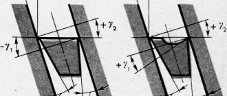
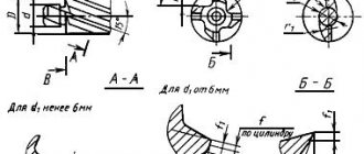
1. Structural elements and geometric parameters of countersinks with cylindrical and conical shanks are indicated in Figure 1 and Table 1, mounted ones - in Figure 2 and Table 2.
Damn.1. Type 1 and 3
Type 1 and 3
Damn.1
Table 1
| 10 | 5 | 3 | 1,2 | 0,4 | 1,0 | 0,8 | 0,5 |
| 10,75 | |||||||
| 11 | |||||||
| 11,75 | 4 | ||||||
| 12 | 6 | 1,5 | |||||
| 12,75 | |||||||
| 13 | |||||||
| 13,75 | 7 | 5 | 2,0 | ||||
| 14 | |||||||
| 14,75 | |||||||
| 15 | |||||||
| 15,75 | 8 | 6 | 0,6 | 1,2 | 1,2 | 1,0 | |
| 16 | |||||||
| 16,75 | |||||||
| 17 | |||||||
| 17,75 | |||||||
| 18 | |||||||
| 18,70 | 9 | 7 | |||||
| 19 | |||||||
| 19,70 | |||||||
| 20 | |||||||
| 20,70 | 2,5 | ||||||
| 21 | |||||||
| 21,70 | 10 | 8 | |||||
| 22 | |||||||
| 22,70 | 3,0 | 0,7 | 1,5 | 1,5 | |||
| 23 | |||||||
| 23,70 | |||||||
| 24 | |||||||
| 24,70 | 11 | ||||||
| 25 | |||||||
| 25,70 | |||||||
| 26 | |||||||
| 27,70 | 12 | 9 | 1,5 | ||||
| 28 | |||||||
| 29,70 | |||||||
| 30 | |||||||
| 31,60 | 13 | 10 | |||||
| 32 | |||||||
| 33,60 | 14 | 3,5 | 0,8 | 1,8 | 1,8 | ||
| 34 | |||||||
| 34,60 | |||||||
| 35 | |||||||
| 35,60 | |||||||
| 36 | |||||||
| 37,60 | 15 | 11 | |||||
| 38 | |||||||
| 39,60 | |||||||
| 40 |
Damn.2. Type 2
Type 2
Damn.2
table 2
mm
| 32 | 2,5 | 1,5 | 4 | 7 |
| 32,6 | ||||
| 33 | ||||
| 33,6 | ||||
| 34 | ||||
| 34,6 | ||||
| 35 | ||||
| 35,6 | ||||
| 36 | ||||
| 36,6 | ||||
| 37 | ||||
| 37,6 | 8 | |||
| 38 | ||||
| 38,6 | 5 | 9 | ||
| 39 | ||||
| 39,6 | ||||
| 40 | ||||
| 41,6 | 3,0 | |||
| 42 | ||||
| 43,6 | 10 | |||
| 44 | ||||
| 44,6 | ||||
| 45 | ||||
| 45,6 | ||||
| 46 | ||||
| 46,6 | ||||
| 47 | ||||
| 47,6 | 3,5 | 6 | 11 | |
| 48 | ||||
| 49,6 | 2,0 | |||
| 50 |
2. The main dimensions of countersinks with intermediate diameters with a conical shank are indicated in Table 2a, mounted ones - in Table 2b, with a cylindrical shank - in Table 2c.
Table 2a
mm
| Morse cone | |||
| 7.80 to 8.50 | 156 | 75 | 1 |
| 8,50 » 9,50 | 162 | 81 | |
| 9,50 » 10,60 | 168 | 87 | |
| 10,60 » 11,80 | 175 | 94 | |
| 11,80 » 13,20 | 182 | 101 | |
| 13,20 » 14,00 | 189 | 108 | |
| 14,00 » 15,00 | 212 | 114 | 2 |
| 15,00 » 16,00 | 218 | 120 | |
| 16,00 » 17,00 | 223 | 125 | |
| 17,00 » 18,00 | 228 | 130 | |
| 18,00 » 19,00 | 233 | 135 | |
| 19,00 » 20,00 | 238 | 140 | |
| 20,00 » 21,20 | 243 | 145 | |
| 21,20 » 22,40 | 248 | 150 | |
| 22,40 » 23,02 | 253 | 155 | |
| 23,02 » 23,60 | 276 | 155 | 3 |
| 23,60 » 25,00 | 281 | 160 | |
| 25,00 » 26,50 | 286 | 165 | |
| 26,50 » 28,00 | 291 | 170 | |
| 28,00 » 30,00 | 296 | 175 | |
| 30,00 » 31,50 | 301 | 180 | |
| 31,50 » 31,75 | 306 | 185 | |
| 31,75 » 33,50 | 334 | 4 | |
| 33,50 » 35,50 | 339 | 190 | |
| 35,50 » 37,50 | 344 | 195 | |
| 37,50 » 40,00 | 349 | 200 | |
| 40,00 » 42,50 | 354 | 205 | |
| 42,50 » 45,00 | 359 | 210 | |
| 45,00 » 47,50 | 364 | 215 | |
| 47,50 » 50,00 | 369 | 220 |
Note. The lengths and can vary within one diameter interval between the minimum and maximum values corresponding to those given in the table for the nearest lower and upper limits of the interval.
For example, for a diameter of 15 mm, the length can vary between 108 and 120 mm with a nominal value of 114 mm, with a tolerance of ±6 mm.
Since the length tolerance is the same as the length (±6 mm), the length can vary between 206 and 218 mm with a nominal value of 212 mm.
Table 2b
mm
| St. 23.6 to 35.5 | 1З | 45 |
| 35,5 » 45,0 | 16 | 50 |
| 45,0 » 53,0 | 19 | 56 |
| 53,0 » 63,0 | 13 | 45 |
| 63,0 » 75,0 | 27 | 71 |
| 75,0 » 90,0 | 32 | 80 |
| 90,0 » 101,6 | 40 | 90 |
Note. Countersink dimensions comply with ISO 3314-75.
Table 2c
mm
| Up to 3.00 | 61 | 33 |
| 3.00 to 3.35 | 65 | 36 |
| 3,35 » 3,75 | 70 | 39 |
| 3,75 » 4,25 | 75 | 43 |
| 4,25 » 4,75 | 80 | 47 |
| 4,75 » 5,30 | 86 | 52 |
| 5,30 » 6,00 | 93 | 57 |
| 6,00 » 6,70 | 101 | 63 |
| 6,70 » 7,50 | 109 | 69 |
| 7,50 » 8,50 | 117 | 75 |
| 8,50 » 9,50 | 125 | 81 |
| 9,50 » 10,60 | 133 | 87 |
| 10,60 » 11,80 | 142 | 94 |
| 11,80 » 13,20 | 151 | 101 |
| 13,20 » 14,00 | 160 | 108 |
| 14,00 » 15,00 | 169 | 114 |
| 15,00 » 16,00 | 178 | 120 |
| 16,00 » 17,00 | 184 | 125 |
| 17,00 » 18,00 | 191 | 130 |
| 18,00 » 19,00 | 198 | 135 |
| 19,00 » 20,00 | 205 | 140 |
Note. The lengths and can vary within one diameter interval between the minimum and maximum values corresponding to those given in the table for the nearest lower and upper limits of the interval. For example, for a diameter of 4 mm, the length can vary from 39 to 47 mm with a nominal value of 43 mm and the length can vary from 70 to 80 mm with a nominal value of 75 mm.
(Introduced additionally, Amendment No. 3).
Section 1. (Changed edition, Amendment No. 4).
DIMENSIONS OF CUTTER PROFILE FOR MACHINING HELICAL GROOVES AND BACKS OF COUNTERSINK TEETH
2.1. Dimensions of the profile of cutters for processing helical grooves and backs of three-tooth countersinks in Figures 3 and 4 in Tables 3, 4, four-tooth countersinks - in Figure 5 and Table 5.
Damn.3
Damn.3
Table 3
mm
| For countersinks with diameter | ||||||||
| until 11 | 5,10 | 2,31 | — | 3,00 | 0,25 | 1,00 | 5,10 | 3,80 |
| 11 » 12 | 6,75 | 3,17 | 0,14 | 3,84 | — | 1,60 | 6,75 | 5,48 |
| 12 » 14 | 6,90 | 3,23 | 4,20 | 7,45 | 1,44 | 2,00 | 6,90 | 8,50 |
| 14 » 15 | 7,85 | 3,78 | 3,65 | 7,50 | 1,46 | 2,25 | 7,85 | 8,65 |
| 15 » 16 | 9,00 | 3,60 | 2,65 | 7,10 | 1,25 | 2,00 | 9,00 | 8,05 |
| 16 » 17 | 8,20 | 4,46 | 4,75 | 9,25 | 2,23 | 2,35 | 8,20 | 10,20 |
| 17 » 18 | 8,20 | 3,98 | 4,80 | 8,70 | 1,48 | 2,45 | 8,20 | 10,10 |
| 18 » 19 | 9,30 | 4,86 | 5,85 | 10,60 | 3,82 | 2,8 | 9,30 | 10,10 |
| 19 » 21 | 8,25 | 4,51 | 5,55 | 10,05 | 2,33 | 2,40 | 8,25 | 10,40 |
| 21 » 23 | 9,65 | 4,97 | 6,80 | 11,80 | 3,13 | 2,80 | 9,65 | 11,95 |
| 23 » 25 | 12,65 | 5,33 | 8,40 | 13,00 | 3,70 | 4,00 | 12,65 | 13,65 |
| 25 » 27 | 15,70 | 5,88 | 4,40 | 12,45 | 0,70 | 3,00 | 15,70 | 15,05 |
| 27 » 30 | 14,00 | 6,92 | 7,50 | 15,05 | 3,09 | 3,65 | 14,00 | 16,35 |
| 30 » 36 | 17,00 | 7,92 | 0,31 | 9,61 | — | 4,00 | 17,00 | 13,67 |
| 36 » 40 | 18,87 | 8,79 | 0,34 | 10,65 | — | 4,44 | 18,87 | 15,17 |
2.2. It is permitted to manufacture countersinks with a chip flute profile different from the specified shape.
Damn.4
Damn.4
Table 4
Dimensions in mm
| For countersinks with diameter | (prev. shutdown by ) | |||
| 10-11 | 10,6 | 7,4 | 5,0 | 20° |
| 11,5-12 | 11,2 | 8,0 | 5,5 | |
| 13 | 11,6 | 8,4 | 6,0 | |
| 14 | 12,2 | 9,0 | 6,5 | |
| 15 | 12,6 | 9,4 | 7,0 | |
| 16 | 14,0 | 10,8 | 7,5 | |
| 17 | 14,6 | 11,4 | 8,0 | |
| 18 | 15,2 | 12,0 | 8,5 | |
| 19 | 15,8 | 12,5 | 9,0 | |
| 20 | 16,4 | 13,2 | 9,5 | |
| 21 | 17,0 | 13,8 | 10,0 | |
| 22 | 17,6 | 14,4 | 10,5 | |
| 24 | 19,0 | 15,8 | 11,5 | |
| 25 | 20,0 | 16,5 | 12,0 | |
| 26 | 20,7 | 17,2 | 12,5 | |
| 27 | 21,4 | 17,9 | 13,0 | |
| 28 | 22,2 | 18,7 | 13,5 | |
| 30 | 23,6 | 20,1 | 14,5 | |
| 32 | 24,8 | 21,5 | 15,5 | 25° |
| 34 | 26,5 | 23,0 | 16,5 | |
| 35 | 27,2 | 23,7 | 17,0 | |
| 36 | 27,9 | 24,4 | 17,5 | |
| 37 | 28,7 | 25,2 | 18,0 | |
| 38 | 29,4 | 25,9 | 18,5 | |
| 40 | 39,5 | 29,5 | 19,5 |
Damn.5
Damn.5
Table 5
mm
| For countersinks of size | cutters | |||||
| 30 to 38 | 63 | 4,0 | 32 | 0,20 | 15,4 | 20,0 |
| 38 » 46 | 5,0 | 38 | 0,25 | 18,6 | 24,1 | |
| 46 » 60 | 80 | 6,0 | 45 | 24,3 | 31,5 | |
| 60 » 70 | 7,0 | 54 | 0,30 | 28,3 | 36,8 | |
| 70 » 80 | 100 | 8,0 | 58 | 0,40 | 32,4 | 42,0 |
INSTALLATION OF GROOVE MILLS WHEN MILLING HELICAL GROOTS OF COUNTERSKINS
3.1. The installation diagram for groove cutters when milling helical grooves of countersinks is shown in Figure 6 and Table 6.
Damn.6
Damn.6
Table 6
Dimensions in mm
| Countersink diameter | Number of grooves | Cutter diameter | Installation size | ||
| From 10 to 11.5 | 3 | 63 | 34,0 | 20° | -0,02 |
| 12 | 34,5 | -0,02 | |||
| 13 | 80 | 43,0 | -0,03 | ||
| 14 | 43,5 | ||||
| 15 | |||||
| 16 | 44,0 | 0,00 | |||
| 17 | -0,11 | ||||
| 18 | -0,2…..* | ||||
| 19 | 44,5 | -0,21 | |||
| From 20 to 21 | -0,21 | ||||
| 22 | 45,0 | -0,07 | |||
| 24 | 100 | 55,0 | -0,33 | ||
| 25 | 55,5 | ||||
| From 26 to 27 | -0,18 | ||||
| 28 » 30 | 125 | 68,5 | -0,22 | ||
| 32 | 69,0 | -0,12 | |||
| From 34 to 36 | 69,5 | 0,00 | |||
| 37 » 40 | 70,0 | 0,00 | |||
| 33 | 4 | 63 | 39,3 | 15° | 10,65 |
| 34 | 40,1 | 11,10 | |||
| 35 | 40,6 | 11,50 | |||
| 36 | 41,60 | 11,60 | |||
| 37 | 41,50 | 11,74 | |||
| 38 | 41,90 | 11,89 | |||
| 40 | 41,40 | 12,90 | |||
| 42 | 42,20 | 13,60 | |||
| 45 | 43,60 | 14,50 | |||
| 48 | 80 | 50,95 | 16,20 | ||
| 50 | 52,75 | 16,65 | |||
| 52 | 52,75 | 17,55 | |||
| 55 | 54,10 | 17,85 | |||
| 58 | 55,60 | 18,15 | |||
| 60 | 56,65 | 18,75 | |||
| 62 | 55,20 | 20,60 | |||
| 63 | 56,10 | 20,50 | |||
| 65 | 57,00 | 20,80 | |||
| 68 | 58,20 | 21,40 | |||
| 70 | 59,40 | 22,20 | |||
| 72 | 100 | 68,20 | 23,60 | ||
| 75 | 69,60 | 23,60 | |||
| 78 | 71,40 | 24,80 | |||
| 80 | 71,40 | 25,40 | |||
________________ * Defect of the original. — Note.
Section 2, 3. (Changed edition, Amendment No. 3).