To ensure high quality, productivity and low cost metalworking when milling with end mills, it is necessary to pay attention to some practical and theoretical aspects discussed in this article.
First, you need to decide on the type of processing: will it be rough milling, in which dimensional accuracy and surface quality are not so important, or finishing milling. After all, first of all, the choice of tool and cutting modes will depend on this.
This article discusses a number of factors that must be taken into account to ensure an efficient face milling process.
Selecting a Face Mill Body
The cost of an imported end mill body with a diameter of 100 mm can exceed 15,000 rubles, so its choice must be taken very seriously.
One of the main parameters of an end mill is the insert pitch. For example, a 100mm diameter end mill with a coarse pitch may have 5 inserts, a medium pitch cutter may have 7 inserts, and a fine pitch cutter may have 10 inserts. The number of inserts for a particular step varies among different tool manufacturers and also depends on the design of the cutter.
When rough milling on equipment with low rigidity, cutting forces can cause excessive vibration, reducing tool life. A decrease in tool life is reflected in the appearance of chipping, which can lead to breakage of the insert, and, in turn, damage to the cutter body.
The use of cutters with large insert pitches allows reducing the required machine power and cutting forces. It is recommended to use such cutters for roughing on machines equipped with spindles with tapers 30 and 40.
The use of coarse pitch cutters is also justified when processing materials that produce continuous chips. Since there is more space to accommodate chips, the possibility of repeated cutting is almost completely eliminated.
When finishing milling, both the depth of cut (about 0.25-0.5 mm) and the feed per tooth (about 0.05-0.15 mm/tooth) are smaller. Since such high machine power is not required as for rough milling, it becomes possible to use end mills with fine insert pitches. A larger number of plates allows processing with a higher minute feed of the table, although the feed per cutter tooth is small. Problems with chip placement also, as a rule, do not arise due to the small depth of cut.
Insert selection
The choice of inserts depends on the type of processing. Sometimes you should choose ground inserts (with greater precision and sharpness of the cutting edge), and sometimes unground inserts. For rough milling, it is recommended to use unground inserts: their cutting edge is equipped with a protective chamfer, which gives it additional strength when processing with large cutting depths and feeds. In addition, their cost is less than ground plates. In general, unground inserts do not provide the same precision and surface quality as ground inserts. This is also due to the low accuracy of the plates themselves, which have different offsets relative to the cutter body. For finishing milling, it is recommended to choose ground inserts that provide high dimensional accuracy as well as surface quality. The geometry of the front surface of the ground inserts is characterized by high sharpness, which is necessary to ensure the cutting process at a small milling depth. If the sharpness of the cutting edge is not enough, then plastic deformation of the metal occurs, which leads to deterioration in the quality of the machined surface and intense wear of the tool.
To ensure high surface quality when milling, it is recommended to use wiper inserts (Wiper technology). One stripper is installed in the cutter body along with conventional inserts, protruding from the body in the axial direction. Thanks to this, the quality of the treated surface is significantly improved. Wiper technology is also used in the production of turning, parting and grooving tools.
Design features and operating principle
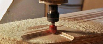
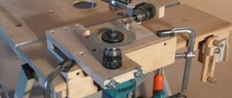
The task of the process is to remove with sufficient accuracy a part of the processed material with cutters moving along a spherical trajectory.
In this way, smooth planes, longitudinal grooves, grooves, and recesses of a complex model are formed. CNC-controlled machines, due to the ability to coordinate movement in three directions, allow you to create a variety of shapes. Depending on the required results, engineers have come up with an impressive range of devices and working mechanisms for them. If for cutting smooth surfaces an element with a sharp cutting edge on the front component is required, then when making recesses for a key it is necessary to use an element with an end zone. There is another option, similar to a drill, but with the ability to remove a layer in two directions.
If you need to form a specific profile in one pass, then a shaped blank is used for a specific case. This is very common in gear manufacturing.
This operation is suitable for a very large range of raw materials. Widely used in the processing of wood, plastic, glass, stone. Even in agriculture, during cultivation, machines operate on this principle.
Wear-resistant coatings and coolant
There are different opinions regarding the use of coolant in milling.
When using a large-diameter cutter, it is difficult to provide an abundant supply of coolant to the cutting zone, because the cutting zone itself is quite large. Periodic heating and cooling of the insert can lead to thermal cracking and breakage of the insert, and possible damage to the cutter body. Modern tool coatings allow milling without coolant with minimal risk of thermal cracks. Some coatings, such as TiAlN, become harder as the temperature increases.
An important argument for dry milling is that the operator observes chip formation, sees the shape and color of the chips, and this allows him to draw a conclusion about the correct choice of cutting modes. Since materials have different compositions and structures, they react differently to thermal influences. For example, cutting carbon steel at the correct speed will actually produce brown chips. At elevated temperatures, carbon enters into a chemical reaction with oxygen in the air, and the chips acquire a blue color - this is what we see as a result of processing. If the chips are black, the cutting speed must be reduced because the temperature in the cutting zone is too high. Stainless steels have a low thermal conductivity coefficient, and heat transfers poorly into chips. When processing stainless steel at optimal conditions, the chips have a light brownish tint. If the chips turn dark brown, reduce the cutting speed.
To prevent the formation of built-up edges when processing stainless steel, a certain amount of heat is still required, the release of which is achieved by selecting the optimal cutting speed. If the chips are cooled too quickly (this happens when coolant is used), the material of the part sticks to the cutting edge and then comes off, resulting in possible damage to the cutting edge. If the feed is too high, build-up problems can also occur. If the feed is too low, plastic deformation of the workpiece may occur.
The main task when milling without coolant is to select such cutting conditions so that the main part of the heat passes into the chips. But when processing flammable materials such as magnesium, it is better to use coolant and keep a fire extinguisher on hand.
Finally, when machining without coolant, it is important to apply a small amount of lubricant to the insert seating surfaces and screws, but do not be overzealous as this can lead to increased insert installation errors.
Types and types of cutters for any metal alloy for a classic milling machine with photo
The tasks performed require the use of several basic configurations. For example, for cutting, an analogue of the well-known circular saw is used. When forming recesses, you need a device similar to a drill. On this principle, division into subclasses is made.
Disk
From the name it is clear that the product has the shape of a disk with edges (depending on the purpose) on the outer side or plane.
Based on the functions they perform, they are divided into:
- Cutting machines are required to separate the workpiece.
- Grooves are necessary for the formation of grooves of different depths and wall shapes (straight, conical, curved).
- Multifunctional. They allow sampling of material in several directions, both across the axis of rotation and along.
Preliminary cutting is carried out with plasma cutters, laser or band saw. As practice shows, in a large number of processes, the last method is the most optimal. A wide range of similar machines is produced, for example,.
Types of end mills (attachments) for metal with photos
The device allows you to touch the plane being processed with all elements on the plane of rotation at once. It is used both to form smooth edges and to create recesses. The picture above shows just such a working body capable of moving in three coordinates. The designs can be inlaid with carbide replaceable edges or solid-cast.
Cylindrical
This pattern is perfect for making corner notches. Due to the combination of the end and radial cutting zones, two sides are processed simultaneously. Typically standing at an angle of ninety degrees. Although there are devices with a different angle.
A logical continuation would be a model with replaceable carbide elements (“corn”). Division into segments reduces the overall load on the working body.
Corner
A common task in mechanical engineering is turning runners for moving components. In this case, you have to make a groove that widens as it deepens, or a cut at a certain angle. This is why such attachments were invented. Usually their use becomes the next phase after the previous devices have developed.
End mill with photo
The advantage of such mechanisms is the ability to create narrow recesses of a curved configuration.
The width is limited by the diameter of the tool. They also modify internal corners after sampling large volumes of alloy. Varieties include finger blades with a conical cutting tip. To remove production products and cooling, a special liquid is supplied through the body.
Shaped
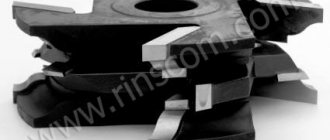
The process of making grooves of specific geometry or processing edges to give it a given profile involves the use of devices with sharp edges, originally made for the project. The advantage of using such technologies is that one operation is enough and subsequent adjustments are not required. There are paired sets - mirror copies. This solves the problem of manufacturing shaped parts that fit together with a minimum gap. Moving slides, gears, etc. are made using this principle.
Worm
If there is a need to form a comb or many parallel grooves, then a block mechanism of this type is used. The teeth can come into contact simultaneously or alternately in a helical arrangement. Such products can be monolithic or stacked. Very often they are used in sets according to processing phases (primary, final and finishing passes).
Ring
These tools act as a drill and speed up the process several times. The hole results in a more precise round configuration. The design itself allows you to make cavities of very different diameters without wasting energy on grinding down the central point. Essentially, a narrow space next to the circle is selected. This subclass also includes a variety of cutters and drills that have a specific shape of edges.
Keyed
Almost every mechanism with rotating elements requires the creation of a groove for installing a key. This hole is made by a special variation of the end organ. The difference is that the size is matched to common standards of the fixing part. The operation is carried out in one pass, since such feathers can implement the functions of a drill and a side cut.
Conical - one of the types of milling tools
Needed to refine the sides from the outside to a given angle. They are usually used to form a finished surface. They are made for specific tasks, have different inclinations and structure of the operating area. Some models are used with a support limit switch.
Spherical
From time to time there is a need to make a round hollow. This is solved with the help of this type of product, similar to drills, the preferred choice for finalizing the correct geometry.
Tool for T-shaped notches
After passing the disk attachment with such a gadget, you can expand the lower sections of the groove for profiling. It is also possible to make indentations in the bottom of the cylinder. A similar manipulation is used in rotating parts, such as a vice.
Prefabricated
This class includes all attachments consisting of a blank with a fastening mechanism and replaceable sharp elements. As you have already noticed, in the picture the style of fasteners can be quite varied. In addition, there are products with changing linear parameters.
Up and down milling
Most face milling operations performed on non-rigid milling machines are performed using the up-milling method (cutting speed and table feed are directed in different directions). But it is recommended to use the down milling method (cutting speed and table feed are directed in one direction).
The following argument is given in favor of down milling: with up milling, the cutting process begins without load on the cutting edge, so plastic deformation of the workpiece material and its hardening actually occur, which leads to excessive wear of the inserts.
Use down milling, and set the width to about two-thirds of the width of the cutter, then when inserting the plates, plastic deformation of the workpiece material will not occur. Next, try changing the milling width and determine experimentally what ratio between cutter diameter and width is optimal for a particular machine and cutter. In this case, it is also possible to observe a change in the roughness of the machined surface.
When the milling width is reduced to half the cutter diameter, plastic deformation of the workpiece material also begins due to a decrease in chip thickness. In this case, it is recommended to increase the feed per tooth of the cutter, which will increase tool life and productivity. When finishing milling, the feed rate is adjusted to the required surface quality.
Classification of cutters for metal
The variety of tasks requires a huge number of working tools. The devices differ in many ways.
Roughly the following groups can be distinguished:
- Manufacturing material (carbide, quick-cutting, ceramics, diamond, etc.).
- The location of the operating teeth (front, end and combined).
- Monolithic or prefabricated.
- Style of cutting parts.
- Direction of rotation.
- Method of securing an organ to an actuator.
This sorting is incomplete, because emerging new goals and advanced technologies force the invention of more modern means at hand that do not fall under the old names. The number of models is constantly increasing.
Result evaluation
To evaluate the performance of face milling, when comparing options, calculate the volume of material removed per unit time while achieving acceptable results in terms of quality. To do this, you need to multiply the width, milling depth and minute feed of the table. The result is a value with the dimension mm3/min.
There are many types of end mills, so choose them carefully. It is best to contact specialists in the field of tools and metalworking technology, then you will not waste time and money in vain.
