Hole alignment
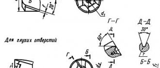
The work is carried out in accordance with GOST 14034-74 and involves the formation of three types of holes:
- A – with a safety cone;
- B – without safety cone;
- R – with an arc generatrix.
R-type holes are in demand with increased requirements for processing accuracy.
Rice. No. 1 Processing a centered part on a lathe
TECHNICAL REQUIREMENTS
2.1. Drills must be made of high-speed steel - in accordance with GOST 19265-73.
2.2. The hardness of the working part of centering drills should be: for drills with a diameter of up to 3.15 mm - 63...65 HRC; for drills with a diameter over 3.15 mm - 63...66 HRC. The hardness of the working part of drills made of high-speed steel with a vanadium content of 3% or more and cobalt of 5% or more should be higher by 1-2 HRC units.
2.3. The roughness parameters of drill surfaces according to GOST 2789-73 should not exceed the values specified in Table 5.
Table 5
µm
| Names of surfaces | Roughness parameters according to GOST 2789-73 | |||
| Version 1 | Version 2 | |||
| The rake surface of the drilling part and the surface of the flutes | — | 6,3 | — | 10,0 |
| Rear surface of drilling and countersinking part | — | 3,2 | — | 6,3 |
| Surface of the clamping cylindrical part | 0,63 | — | 1,25 | — |
2.2, 2.3. (Changed edition, Amendment No. 2).
2.4. Cracks, nicks, rough spots and tarnished colors are not allowed on the surfaces of centering drills (with the exception of grooves, where tarnished colors are allowed at the point where the wheel exits).
2.5. Maximum deviations in the dimensions of combined drills should not exceed: the diameter of the drill part. . . k12; diameter of the clamping cylindrical part. . . h9; cone angles 60° and 75°. . . minus 30′; cone angle 120°. . . ±1°. Note. The dimensions of the nominal diameters of the drilling part should be measured at the beginning of the cutting part. (Changed edition, Amendment No. 3).
2.6. Drills of types A, B and C must have a reduction in diameter on the drilling part towards the shank (reverse taper) within 0.05-0.10 mm per 10 mm of length. (Changed edition, Amendment No. 2).
2.7. The thickening of the core of combination drills towards the shank by 5 mm in length should be:
| for drills up to 3.15 mm diameter | 0.40 mm |
| » » » St. 3.15 mm | 0.25 mm |
2.8. The tolerance for radial runout of the auxiliary edges of the drilling part relative to the axis of the clamping part should be no more than:
| for drills up to 3.15 mm diameter | 0.03 mm |
| » » » St. 3.15 mm | 0.04 mm |
2.9. The axial runout tolerance, checked at the center of the cutting edges, should be no more than:
| for drills up to 6.0 mm diameter | 0.10 mm |
| » » » St. 6.0 mm to 10.0 mm | 0.13 mm |
| » » » St. 10.0 mm | 0.15 mm |
For drills with a diameter of up to 6 mm, instead of the tolerance of the end runout of the drilling part, it is allowed to check: the difference in half the angle at the tip of the drill, which should not be more than 1°30′; symmetry tolerance in radius expression of the transverse edge relative to the axis of the clamping part of the drill:
| for drills up to 3.15 mm diameter | 0.05 mm |
| » » » St. 3.15 mm | 0.10 mm |
(Changed edition, Amendment No. 2).
2.10. The difference in the widths of the feathers on one drill should be no more than:
| for drills up to 3.15 mm diameter | 0.07 mm |
| » » » St. 3.15 mm | 0.10 mm |
2.11. The values of average time to failure and 95% failure-free operating time of drills made of R6M5 steel, version 2, under the test conditions specified in Section 4, must be no less than those given in Table 6.
Table 6
| Diameter of the drill bit, mm | Operating time (number of holes machined) with drill type | |||
| A, R, C | IN | |||
| average | 95% | average | 95% | |
| 0,5, 0,63, 0,8, 1,0 | 130 | 39 | 90 | 27 |
| 1,25, 1,6 | 160 | 48 | 120 | 36 |
| 2,0 | 220 | 66 | 145 | 43 |
| 2,5, 3,15 | 250 | 75 | 160 | 48 |
| 4,0, 5,0 | 150 | 45 | 100 | 30 |
| 6,3, 8,0, 10,0 | 130 | 39 | 80 | 24 |
Note. For drills of version 1, the correction factor for the average and specified service life is 1.3. (Changed edition, Amendment No. 3).
2.12. The criterion for failure of centering drills with a diameter of up to 3.15 mm is breakage, and from 4 mm and above - wear on the rear surface in accordance with Table 7.
Table 7
mm
| Drill bit diameter | |
| 4,0, 5,0 | 0,4 |
| 6,3, 8,0, 10,0 | 0,5 |
2.11, 2.12. (Introduced additionally, Amendment No. 2).
2.13. On each drill the following must be clearly marked: the diameter of the drill part; manufacturer's trademark; drill designation (last four digits); steel grade. Notes:
1. On drills with a diameter of less than 10 mm, it is allowed not to mark the drill designation.
2. Steel grades R6M5 are allowed; R6AM5 should not be marked.
3. It is allowed to mark the letters HSS instead of the high-speed steel grade; for steel grades containing cobalt, the letters HSS C, while the grade is now indicated only on labels.
2.14. Packaging, marking of transport and consumer containers - in accordance with GOST 18088-83.
2.13, 2.14. (Introduced additionally, Amendment No. 3).
Centering tool
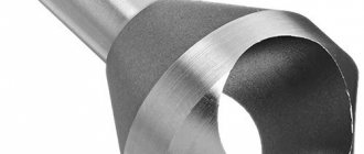
The key tool for centering holes is a center drill. Products are made from steel R6M5, R18 and VK6M in accordance with GOST 14952-75. Drills with and without a safety cone are available for sale (Figures 2 and 3, respectively).
Rice. No. 2 Drill with safety cone
Rice. No. 3 Drill without safety cone
In some cases, the cone is replaced by a radius or a twisted groove. The latter ensures efficient removal of chips during work.
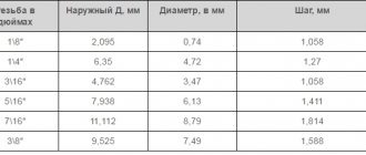
Centering holes with a diameter of 1 to 6 mm is performed only using a drill. If the indicated dimensions are increased, a countersink is additionally used. Typical hole parameters are presented in the table.
Table No. 1 Dimensions of center holes
When carrying out work, the following defects should be avoided:
- violation of the size of the hole or its shape;
- the appearance of nicks inside the hole caused by using a dull drill;
- obstruction of holes and parts.
Most of the listed defects can be eliminated, but this requires additional equipment and effort.
Rice. No. 4 Examples of correct and incorrect alignment
APPENDIX 1 Reference
INFORMATION ON THE APPLICATION OF CENTER HOLE SHAPE
| Center hole shape | Application |
| a) In cases where after processing there is no need for center holes. b) In cases where the safety of the center holes during their operation is guaranteed by appropriate heat treatment | |
| In cases where the center holes are a base for repeated use, as well as in cases where the center holes are retained in finished products | |
| For mandrels and plug gauges | |
| For large shafts (same purpose as form A) | |
| For large shafts (purpose similar to form B) | |
| In cases where increased processing accuracy is required | |
| For installation work, transportation, storage and heat treatment of parts in a vertical position | |
| For tool tapers: Morse, metric, etc. |
APPLICATION. (Changed edition, Amendment No. 1).
Why is alignment performed?
Centering for drilling holes avoids the following problems:
- Excessive vibration when processing a workpiece due to a shift in the center of mass.
- Increased friction forces, decreased equipment performance.
- Premature wear of oil seals, bearings and other supporting components of the machine.
- Increased processing complexity.
- Increased energy consumption.
Proper alignment significantly reduces the risk of defects and speeds up the work process.
Alignment methods
Centering for drilling holes avoids the following problems:
- Using a ruler. A simple method used in the manufacture of low-critical parts due to low accuracy. Positioning of holes is carried out using a ruler, feeler gauges and axial gauges.
- Radial-axial method. Centering using dial indicators. The method is relevant when working with large couplings and is used in many modern industries.
- Reverse indicator method. Centering involves taking measurements at two points. The result is simultaneous control of angular and parallel displacement.
- Centering by laser. Carrying out work using laser beams, indicator blocks and a calculation module.
Laser alignment is most widespread due to its high speed, accuracy and simplicity.
Rice. No. 5 Set of devices for laser alignment
Domestic use
Despite the fact that center tools are considered professional, many home craftsmen successfully use them. Such devices are common among radio amateurs, who often drill small holes in printed circuit boards. Having increased rigidity, centering tools are excellent for such work.
In domestic conditions, devices are mainly used whose diameter is 0.05-0.08 cm. This is due to the fact that a small cutting element makes it possible to solve many household problems with great efficiency.
One of the procedures that is carried out using a centering drill is the drilling of screw and screw elements. Often it is impossible to unscrew them with an ordinary screwdriver. Using a drill, the heads of the screws/screws are drilled out and then easily unscrewed. Drilling is especially easy if the fastener parts have slots for Phillips screwdrivers. If the slots are intended for straight screwdrivers, you need to tilt the head to mark the entry area of the drilling tool.
Every home craftsman can easily buy a center drill of any size. Currently, stores offer many varieties of drilling tools, both Russian and imported.
If you read reviews from home craftsmen, it becomes obvious that the most common products are from. These drills are high quality, reliable, and have a long service life.
Dormer center drills are made from high-speed metal. In addition, they undergo special heat treatment to ensure maximum hardness of the device. After passing all the technological procedures, a product is created that can easily drill through hard materials, for example, stainless steel.
The manufacturer adds cobalt to the steel from which Dormer center tools are made. This allows the cutting element to remain hard even in high temperature conditions. The wear resistance of Dormer products is very high. It is not for nothing that drills of this brand are given such a long warranty.
A significant characteristic of Dormer tools is that they are self-centering. Thanks to this, it is possible to create holes with high location accuracy. Like other manufacturers, it produces centering devices of various sizes.
Alignment with a laser: step-by-step instructions
Alignment using a laser is performed in a certain order:
- checking permissible misalignment according to standards;
- placement of components in seats;
- fixing detectors on the surface of rotating parts;
- selection of the alignment program in the control unit;
- manual rotation of the shaft for the purpose of reading the primary data by the system;
- correction of the position of elements in accordance with the recommendations of the device;
- re-rotate the shaft.
If, as a result of repeated rotation, the deviations do not exceed the norm, the alignment can be considered complete. All that remains is to form the hole using the existing drill.
When working with centering drills, the correct selection of the cutting mode is important. If the drill is fed manually, you should avoid sudden movements - this will prevent biting, chipping and other defects.
Use at home
Despite the fact that centering drills are professional, many home craftsmen have found successful use for them. Such drills are very popular among radio amateurs, who often have to drill small-diameter holes in printed circuit boards. Possessing high rigidity due to the features of their design, centering type drills in such situations are more preferable than a standard small-diameter drilling tool.
Drilling holes in a printed circuit board
One of the operations that can be successfully performed using a centering tool is drilling out screws or screws that cannot be removed with a regular screwdriver. Using a centering tool, the heads of such recalcitrant fasteners are simply drilled out, after which they can be easily unscrewed. The easiest way to solve this problem is to drill out the head of a screw or screw, which has slots for Phillips-type screwdrivers. If we are talking about a head with slots for a straight screwdriver, then it must first be marked to indicate the exact location of the drill.
Centering drill with screw sharpening and Morse taper shank
It will not be difficult for any home craftsman to purchase a centering tool of any diameter. Today there is a large assortment of drills available for free sale, including both domestic and foreign brands.
If we talk about the preferences of home craftsmen, then, judging by reviews and recommendations, centering drills produced under the well-known Dormer brand are very popular among them. This tool is distinguished by high quality workmanship, as can be judged even from its photo; it is reliable and durable in use.
Dormer center drills are made from high speed tool steel HSS
The centering tool TM Dormer is made of high-speed steel and is subjected to special heat treatment to ensure high hardness of the finished product. As a result of such technological manipulations, a tool is obtained that can easily drill very hard metals, including stainless steel.
The manufacturer adds cobalt to the metal from which Dormer centering drills are made, which allows the cutting tool to maintain its original hardness even at elevated processing temperatures. The wear resistance of the products of this brand also deserves praise.
