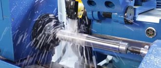
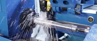
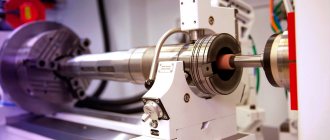
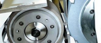
Centerless grinding is considered one of the most productive and popular processing of metal parts and workpieces. When performing it, the workpiece is not fixed in a chuck or along a central axis, as with other types of grinding. The part is placed between two grinding wheels and is held using a special support with a bevel, due to which it is pressed against the drive wheel (smaller diameter). The removal of the metal layer is carried out by an abrasive wheel of a larger diameter, which rotates at a speed 80-100 times higher than the rotation speed of the small (leading) grinding wheel.
Operation of centerless grinding machines
Centerless grinding is carried out on centerless grinding machines. They are divided into several types depending on how the grinding wheels are arranged:
- for external and internal grinding;
- special;
- universal.
These machines process shafts, sleeves, rods, bearing parts, pistons and other parts similar to rotating bodies. The operation of centerless cylindrical grinding machines can proceed according to two schemes:
- with longitudinal feed of the part;
- with transverse feed (plunging).
Longitudinal feed is suitable for processing long workpieces with the same diameter along the entire length of the surface. Plunge centerless grinding is used in cases where the product has a shaped or stepped configuration, parts or recesses of any size protruding on the surface.
Cylindrical centerless grinding provides high quality processing of metal surfaces. Centerless grinding machines can be easily combined into entire automatic lines, which significantly increases their productivity and provides control over the results of their work during the mass production of metal products.
General concept of grinding
- In primitive cases, use hard granular sand or harder emery, pour it onto a hard surface and rub the object being processed against it. The angular grains, rolling between both surfaces, produce a large number of impacts, from which the protruding places of these surfaces are gradually destroyed, and the grinding grains themselves are rounded and disintegrated into pieces. If one of the surfaces is soft, the grains are pressed into it, remain motionless, and produce a series of parallel scratches on the second surface; in the first case, a matte surface is obtained, covered with uniform pits, and in the second, a so-called “stroke” gives the surface a shine that turns into polishing, when the stroke is so small that it becomes invisible to the eye. So, when grinding two copper plates against each other with emery, both will turn out matte, and the same emery, being glued to the surface of the paper, will impart shine when rubbed against the brass surface.
- Fragile, hard glass wears off more than a soft and elastic metal plate, and diamond powder can wear off the surface of the diamond itself, and pieces of quartz can be processed on a sandstone sharpener. The pits produced by the grains of emery are smaller, the finer the grains themselves; Therefore, grinding can produce the most precisely machined surfaces, as is done when grinding optical glasses.
This is interesting: Hole processing: types of operations and tools used
Cylindrical centerless grinding of external surfaces
When centerless grinding of external surfaces, parts and workpieces are processed without fastening in the centers. Removing the allowance and removing roughness is done with a cutting wheel, while the part itself is located between two circles - the working and driving ones. They rotate in the same direction, but at different speeds: usually the speed of the grinding wheel is almost 100 times higher than the speed of the driving wheel. It is the difference in speeds that ensures the grinding of products.
If necessary, you can change the position of the driving circle in relation to the working one. This will ensure good clamping of the part to the support (during plunge-cut grinding), and with the longitudinal method of external centerless grinding it will ensure correct feeding of the part into the processing zone.
Centerless cylindrical grinding machine 3M182
| Parameter name | 3M182 | — |
| Main settings | ||
| The largest guaranteed diameter of the installed product, mm | 25 | |
| The largest permissible diameter of the installed product, mm | 35 | |
| Minimum diameter of the installed product, mm | 0.8 | |
| Smallest diameter recommended for plunge grinding | 2,5 | |
| Maximum length of processed products (limited by the rigidity and stability of the products) during through grinding, mm | 170 | |
| Maximum length of processed products (limited by the rigidity and stability of the products) during plunge-cut grinding, mm | 95 | |
| Height from the base of the machine to the axis of the circles, mm | 1060 | |
| Height from the bridge mirror to the axis of the circles, mm | 160 | |
| Grinding wheel | ||
| Maximum outer diameter, mm | 350 | |
| Smallest outer diameter, mm | 280 | |
| Maximum height, mm | 100 | |
| Hole diameter, mm | 203 | |
| RPM | 1910 | |
| Peripheral speed, m/sec | Up to 35 | |
| Leading Circle | ||
| Maximum outer diameter, mm | 250 | |
| Smallest outer diameter, mm | 200 | |
| Maximum height, mm | 100 | |
| Hole diameter, mm | 127 | |
| Maximum angle of inclination in the vertical plane, degrees | ±5 | |
| Maximum tilt angle in the horizontal plane, min | ±30 | |
| RPM during operation (stepless regulation) | 17—150 | |
| Number of revolutions per minute when straightening | 300 | |
| Grinding head | ||
| Grinding wheel spindle end size according to GOST 2323-67, mm | 80 | |
| Maximum installation movement, mm | 90 | |
| The greatest accelerated movement during plunge-cut grinding, mm | 20 | |
| Working movement per one division of the feed mechanism dial, mm | 0,001 | |
| Working movement per one revolution of the feed mechanism dial, mm | 0,08 | |
| Working movement of jog feed from the handle, mm | 0,001 | |
| Working displacement by plunge mechanism, mm | Up to 0.95 | |
| Feed rate during plunge-cut grinding is the highest, mm/min | 10 | |
| Feed rate for plunge-cut grinding is the lowest, mm/min | 0,06 | |
| Grandmother | ||
| Maximum displacement, mm | 80 | |
| Movement of the feed screw dial by one division, mm | 0,05 | |
| Movement of the feed rate dial per revolution, mm | 6 | |
| Wheel dressing mechanism | ||
| Transverse movement of diamond per dial division, mm | 0,01 | |
| Transverse movement of the diamond per one revolution of the dial, mm | 1,5 | |
| Maximum speed of diamond movement in the longitudinal direction, mm/min | 250 | |
| The speed of diamond movement in the longitudinal direction is the lowest, mm/min | 30 | |
| Maximum rotation angle of the copier, gra | ±2 | |
| Caliper | ||
| Maximum adjustment movement of the caliper knife in height, mm | 10 | |
| Hydraulic drive of the plunge mechanism | ||
| Pump capacity, l/min | 12/8 (double) | |
| Nominal pressure, kgf/cm2 | 10 | |
| Hydraulic tank capacity, l | 100 | |
| Lubrication unit | ||
| Capacity of the grinding wheel head spindle bearing lubrication pump, l/min | 5 | |
| Capacity of the spindle headstock bearing lubrication pump, l/min | 1,6 | |
| Grinding wheel bearing tank capacity, l | 65 | |
| Capacity of the drive wheel bearing tank, l | 15 | |
| Cooling unit | ||
| Pump capacity, l/min | 45 | |
| Magnetic separator throughput, l/min | 50 | |
| Capacity, tank, l | 120 | |
| Drive, dimensions and weight of the machine | ||
| Type of supply current | AC three-phase, current frequency 50Hz | |
| Supply voltage, V | 380 | |
| Electric drive voltage, V | 380 | |
| Control circuit voltage, V | 110 | |
| Voltage of local lighting circuits, V | 36 | |
| Signaling voltage, V | 5,5 | |
| DC voltage, V | 110 | |
| Grinding wheel drive motor - type | AO2-51-4-S1 | |
| Grinding wheel drive electric motor - power, kW, | 7,5 | |
| Grinding Wheel Drive Motor - RPM | 1460 | |
| Drive circle drive motor - type | PBST-22-V | |
| Drive circle drive electric motor - power, kW | 0,85 | |
| Drive Circle Drive Motor - RPM | 2200 | |
| Electric motor for driving an electric machine amplifier - type | EMU-12A-S1 | |
| Electric motor for driving an electric machine amplifier - power, kW | 1,2 | |
| Electric machine amplifier drive motor - rpm | 2900 | |
| Hydraulic pump drive electric motor - type | AOL2-21-4-S1 | |
| Hydraulic pump drive electric motor - power, kW | 1,1 | |
| Hydraulic pump drive motor - rpm | 1400 | |
| Grinding wheel spindle bearing lubrication pump drive motor - type | AOL21-4-S1 | |
| Electric motor drive of the grinding wheel spindle bearing lubrication pump - power, kW | 0,27 | |
| grinding wheel spindle bearing lubrication pump drive - rpm | 1400 | |
| Electric motor drive for lubrication pump of drive wheel spindle bearings - type | AOL11-4-S1 | |
| Electric motor driving the drive wheel spindle bearing lubrication pump - power, kW | 0,12 | |
| driving wheel spindle bearing lubrication pump drive - rpm | 1400 | |
| Cooling pump drive motor - type | PA-45-S1 | |
| Cooling pump drive electric motor - power, kW | 0,15 | |
| Coolant Pump Motor - RPM | 2800 | |
| Magnetic separator drive motor - type | AOL11-4-S1 | |
| Magnetic drive electric motor - power, kW | 0,12 | |
| Magnetic drive motor - rpm | 1400 | |
| Grinding wheel dressing drive electric motor - type | PL-062-S1 | |
| Grinding wheel dressing drive electric motor - power, kW | 0,09 | |
| Grinding wheel dressing drive motor - rpm | 1440 | |
| Drive wheel dressing drive electric motor - type | PL-062-S1 | |
| Drive wheel dressing drive electric motor - power, kW | 0,09 | |
| Drive Wheel Dressing Motor - RPM | 1440 | |
| Electric motor for driving rapid movement of the grinding headstock - type | AOL12-4-S1 | |
| Electric motor for driving the accelerated movement of the grinding head - power, kW | 0,18 | |
| Grinding headstock rapid movement motor - rpm | 1400 | |
| Total power of electric motors, kW | 11,67 | |
| Machine dimensions (length X width X height), mm | 2230 x 1455 x 2120 | |
| Weight of the machine with attached equipment, kg | 3470 |
Moscow, Mechanical Engineering. Encyclopedia 2002. Edited by K.V. Frolova
Internal centerless grinding
Internal centerless grinding can be carried out using drive, support and pressure rollers and on rigid supports. This method has its advantages, for example, there is no axial runout of the spindle. The disadvantages include two points:
- the possibility of deformation of the workpiece under the influence of the pressure roller;
- deterioration of grinding accuracy due to runout of the support and drive rollers.
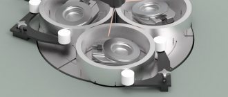
When performing internal centerless grinding of holes, the workpiece is placed on the machine between three rollers that rotate. The abrasive wheel also rotates on the shaft, and during the rotation process it is inserted into the hole that needs to be processed.
Equipment and tools used
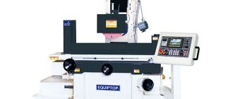
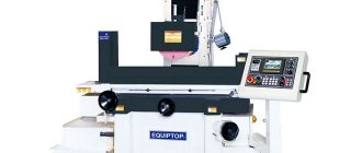
Grinding work on metal is carried out using special machines or manually. Grinding machines are divided into groups:
- cylindrical grinding;
- internal grinding;
- roughing and grinding;
- special spline grinders;
- surface grinding machines with round or flat table;
- lapping and polishing.
Such a variety of machines makes it possible to obtain a roughness coefficient of 0.32 microns during ordinary metal grinding, and up to 0.08 microns during precision processing. With the use of special abrasive compounds, this figure reaches 0.02 microns.
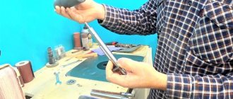
The second method involves the use of hand tools. These can be electric grinders, drills or devices for manual processing (abrasive wheels, belts, blades, various files and needle files).
Processing parts before grinding
Polishing a metal surface can only begin after preparation has been completed. First of all, the part is cleaned of rust, scale, and drops remaining after welding. You can use metal brushes for this. After this, rough chips, dents and bumps are corrected. After rough processing of the metal, the milling process takes place. A layer of metal is mechanically removed from the workpiece.
When processing on industrial equipment is completed, it is necessary to harden the metal. Annealing increases the strength of the part. Metal is often enriched with various chemicals that improve its characteristics.
Before grinding, you need to check the part for visual defects and inspect it for irregularities.
Types of work on grinding metal products
Metal grinding is one of the most important stages in the final surface treatment of metal products. Thanks to grinding, it is possible to significantly reduce surface roughness and bring the required holes to the specified size.
One type of final metal surface treatment is grinding. It involves removing the surface layer using various tools using abrasive materials. Metal grinding allows you to solve the following problems:
- remove all remaining irregularities after preliminary finishing;
- achieve high accuracy of the required dimensions of the part (geometric dimensions, internal and external diameters, compliance with the given shape of the surface of higher orders: parabola, ellipsoid, and so on);
- giving the detail aesthetic appeal.
Main types of grinding
There are several ways to polish metal. They involve the use of different abrasive materials and equipment. To automate all processes and reduce manual labor, CNC grinding machines are used.
Sanding flat surfaces
Flat grinding is used for large body parts that often end up in finishing. When grinding the surface, it is worth considering some features:
- To fix a flat workpiece on the workbench, mechanical or magnetic clamps are used.
- The main rotation force is transmitted to the abrasive wheel. The reciprocating force acts on the workpiece itself.
In order not to spoil the part, it is necessary to use a water cooling system that will supply liquid to the workpiece. Thus, you can work at high speeds without the risk of damaging the work surface.
Internal grinding
Situations often arise when it is necessary to carry out internal cylindrical grinding. During this process, the abrasive wheel is located inside the workpiece. To increase the efficiency of the work carried out, it is necessary to use coolant.
Internal grinding
Gear grinding
Various equipment uses gears. They are connecting elements, and if one of the wheels fails, the entire mechanism will stop. However, these are complex parts that require special equipment to process. Before grinding, the manufacturer can carry out additional hardening of the wheel teeth, which will significantly complicate the grinding process.
Abrasives used
- circle (the range of diameters is quite wide);
- shaft (for internal processing);
- tape or circular tape;
- sheets (paper or special fabric can be used as a backing).
Natural (natural) and artificial stone are used as abrasive chips. At industrial enterprises and processing shops, abrasive tools with artificial material are used. It has improved physical and mechanical characteristics.
Did you like the article? Be sure to share your opinion in the comments section!
Source
The essence and features of the process
Metal grinding is the processing of metal and alloys using abrasive materials, which allows you to correct uneven metal surfaces and smooth out roughness. For this purpose, special industrial and manual equipment is used.
- During grinding, using special equipment, the metal surface is brought to a certain degree of roughness.
- This is the final stage, which is not used to correct serious defects or remove a large layer of material.
- For faster and more efficient grinding, the metal is initially heated.
During the final stage of work, many features are taken into account.
