- Additional articles:
- OVERVIEW OF PROCESSING CENTERS OF OWN PRODUCTION
- CRITERIA FOR SELECTION OF MILLING EQUIPMENT
- 4-AXIS MILLING MACHINES
- MEDIUM MILLING MACHINES
- VERTICAL MACHINING CENTERS
Performing metalworking operations, including milling, requires technologically complex equipment, the choice of which depends on the availability of special engineering knowledge and practical experience. The variety of designs of milling machines requires the preliminary drawing up of a production flow chart, where all stages of product manufacturing are indicated with detailed characteristics:
- Types of technological operations.
- Execution sequence.
- Frequency of performing similar operations
- The required time to perform certain actions.
A clear idea of the future production process will allow you to avoid making mistakes when choosing equipment and eliminate the possibility of unnecessary waste of funds.
General parameters of milling machines
Dimensions of the working area . An important criterion that allows you to determine the dimensions of manufactured parts. It is certainly clear that small-sized machines are needed to produce small parts. The area of the work table should be only slightly larger than the size of the workpiece - this is only necessary for the convenience of fixing it. If there is a vacuum table, its dimensions may coincide with the dimensions of the parts.
The height of the portal is determined by the distance from the plane of the work table to the edge of the cutting tool. The range of motion of the spindle must also be considered. The larger these two values are, the wider the range of types of products that can be produced using this equipment.
Methods of machine control . Here we will look at some ways to automatically control the operation of a milling machine, allowing you to minimize manual labor, increasing labor productivity.
- Operation of a machine under the control of a personal computer during single production of products. Here, the necessary technological modes (spindle rotation speed, feed rate of the workpiece or working tool, etc.) are entered into the preset program.
- In mass production, when the demand for specific products is high and there is no need to frequently change the control program, special controllers are used. All technological information is entered using a flash card.
- Special control systems allow you to automatically change operating modes, readjust tools, and provide feedback to electric drives.
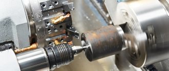
Spindle characteristics . Here attention is paid to such parameters as rotation speed, power of the drive motor, acceleration and stopping parameters (smoothness, time), noise level, and the presence of an automatic cutting tool change function.
A water-cooled spindle produces less noise, and the machines themselves are less expensive. Air-cooled spindles are used on machines for large-scale production.
Complete set of machines . Machine equipment of the same model range, having a similar design, differs in its technical characteristics:
- In terms of drive power and, as a consequence, the mass of processed parts.
- According to the maximum spindle stroke.
- Based on the availability of chip removal and tool cooling systems.
- An automatic tool changer or vacuum table can improve machine productivity.
- According to the type of electric motors used.
The parameters of the bed are important. Vibrations that are inevitable during processing must be damped by massive structural elements. An all-welded frame is preferable. But in large-scale mass production, the cast frame provides higher precision in the manufacture of products.
Purpose and scope
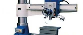
The 6P82 cantilever milling machine is designed to work with all types of cutters and perform a wide range of work:
- processing of side surfaces;
- creating protrusions and recesses;
- milling straight and curved grooves.
The model is designed for processing metals of different hardness and viscosity:
- cast iron;
- steels;
- bronze;
- alloys of non-ferrous metals.
Installation of devices increases the number of technological operations. On the machine, from one installation, the upper surface is processed, the ends are milled, holes are drilled and bored.
Important!
When installing a special tool, plexiglass, polyurethane and other dense materials are processed on the 6P82 milling machine.
The main products produced on the 6P82 model are rectangular-shaped parts of varying complexity: plates, gaskets, inserts, pillows and others.
Types of milling machines
All types of machines can be divided into several types, differing in design layout and list of operations performed.
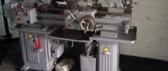
Horizontal milling machine . It has a horizontal axis of rotation of the spindle with a fixed working tool - a milling cutter. The work table makes translational movements to feed the workpiece. Machine tools are used in mechanical and tool workshops for the manufacture of various parts.
Universal milling machine . The most widely used processing equipment for single or small-scale production. It is distinguished by the design of the desktop mechanism, which allows it to rotate in a horizontal plane. This device allows you to mill spiral grooves.
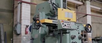
Vertical milling machine . The spindle head is vertical. The main movement drive is similar to the design of conventional vertical drilling machines. The machines have three directions of feed movement: longitudinal, transverse and in the vertical plane.
Used for milling grooves for keys, complex shaped dovetail or L-shaped grooves.
Longitudinal milling machine . It is used for processing large surfaces and shaped profiles of large products. The simultaneous use of several working tools increases equipment productivity.
Copy milling machine . Used for the manufacture of shaped surfaces of complex shapes. It has a work table rotating in a horizontal plane, on which the copier and the workpiece are simultaneously fixed. By rotating, the copier forces the table to move according to its outline.
Symbols of serially produced metal-cutting machines
In more detail - Symbols of commercially produced milling machines.
6
— milling machine (group number according to
ENIMS )
D
– series (generation) of the machine (B, K, N, M, R, T), for example, 682, 6B82Sh, 6K82Sh, 6N82Sh, 6D81Sh, 6R82Sh, 6T82Sh
8
– subgroup number (1, 2, 3, 4, 5, 6, 7, 8, 9) according to the ENIMS classification (8 - horizontal milling)
1
– machine version – standard size (0, 1, 2, 3, 4) (1 – work table size – 250 x 1000)
Letters at the end of the model designation:
G
– horizontal cantilever milling machine with a fixed table
TO
– a machine with a copying device for processing curved surfaces
B
– a machine with increased productivity (increased range of spindle speeds, increased power of the main movement motor).
P
– increased accuracy of the machine - (n, p, v, a, s) according to GOST 8-82
Sh
– widely universal machine
F1
– a machine with a digital display device (DRO) and preset of coordinates
F2
– machine with CNC positional numerical control system
F3
– machine with contour (continuous) CNC system
F4
– multi-purpose machine with CNC contour system and tool store
Rubicon, LLC
Main components and mechanisms
When the main electric motor is turned on, the electromagnetic clutch is activated, and the movement is transmitted through a gear system to the tool head with spindles. By rotating the flywheel, the trunk in which the gearbox is mounted is moved. The desired speed is set by sequentially switching on individual stages, for which a rack and pinion gear mechanism is used. Further, through the cam clutch, the movement is communicated to the rotating head of the machine.
To turn on the feed box, do this. Turn on the electric motor that drives the feed mechanism. Through a system of gear wheels, torque is transmitted to the input shaft, which is interlocked with a friction clutch, which protects the mechanism from overload. The shaft begins to move the work table.
To combine all the main catches of the machine, a console is designed, through which all variable coordinates are controlled. The activation of the mechanisms is rigid, using cam clutches separate for each unit. If necessary, all drives can be reversed.
Design and its features
All working units are mounted directly on the cast machine bed. The spindle does not change its position and only moves forward during operation.
Trunk and earrings
The trunk moves horizontally, parallel to the spindle, along guides located in the upper part of the frame. A motor is installed in the rear part of the trunk body. It turns on when installed in front of the rotary head and rotates the tool installed in it.
When processing massive parts, the mandrel with the tool is fixed with earrings. They move along guides at the bottom of the trunk.
Gearbox
The gearbox is located directly in the hollow frame of the machine, in its upper part. An elastic coupling connects the gearbox to the electric motor shaft and at the same time eliminates misalignment of rotating parts.
To carry out inspection and maintenance of the gearbox, there is a special door on the right side of the frame.
Gearbox
The shift box is located directly above the gearbox, in the trunk. With its help, the required cutting mode is set using the handles located on the right, on the trunk body.
Gearbox
The console houses the feed box. The handles on the front wall of the unit set all feeds for movement in any direction. The feed drive is independent, powered by a motor located directly in the console body.
An adjustable ball clutch is built into the feed box. It protects against overloads by disconnecting the box from the motor shaft.
Overall dimensions of the workspace
Overall space is determined by the following parameters:
- table dimensions 1250×320 mm;
- maximum longitudinal movement 800 mm and transverse 240 mm;
- distance from the spindle axis to the table surface is 30–450 mm;
- the distance from the axis of the rotating spindle head to the frame guides is 260–280 mm.
One division of the dial is equal to a displacement of 0.05 mm in any direction.
Selection principles
When choosing equipment you need to pay attention to some features:
- First of all, you need to evaluate the dimensions of the equipment. It should be freely located in the room and have enough space on different sides.
- The material from which the structure and frame are made. If hard materials will be processed on the machine, the frame must be made of metal.
- Engine power. The most important parameter when choosing. The more powerful the electric motor, the harder the materials can be made.
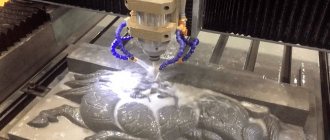
- Cooling. To ensure that the cutter does not overheat and the surface being processed does not become unusable, it is necessary to choose equipment with cooling. Water and air systems are available for sale. For water ones, you need to think about how to arrange the hoses and container for supplying liquid. Air systems need to be cleaned of dust that accumulates on cleaning filters.
- Control system. It is better to choose a model with the ability to adjust the spindle speed.
There is no point in purchasing expensive equipment if it will not be used regularly. There are models of machines for professionals and amateurs. There are also machines designed for large enterprises and their own workshops.
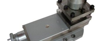
Equipment for the machine
Manufacturing technology
In order not to buy a powerful machine for mass production, you can assemble homemade equipment. On the Internet there are drawings of structures and mechanisms for metal processing that are made by hand.
First of all, you need to prepare materials and tools. It is advisable to make the frame from metal corners or profiles. The metal is joined by welding. The working surface is made of a single sheet of metal more than 3 mm thick. An engraver, drill or drill is used as a motor. Their power is sufficient for tabletop machines through which soft woods and thin sheet metal will pass. To secure the working part, you need to build a frame. It is made from plywood, chipboard, MDF, durable plastic. Fasteners are self-tapping screws, bolts, nuts. It is necessary to attach guides to the structure along which the working part with the cutter will move.
A milling machine is an indispensable element of enterprises engaged in metalworking. If there is a lack of funds, you can make a tabletop mechanism for processing wood, plastic and sheet metal.