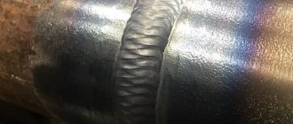
The non-destructive testing laboratory of the Olimp IC carries out vacuum-bubble testing of welds, heat-affected zones, and base metal. The service is provided in Moscow and throughout Russia.
NDT specialists can visit the site the next day after receiving the application. Tests and measurements are carried out by employees certified to qualification levels II and III.
Rostechnadzor and other regulatory agencies trust the conclusions on the compliance of the inspection object with the requirements of technical documentation issued by LNK.
Find out the cost of the service - send a request
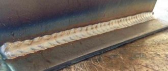
Vacuuming of welds
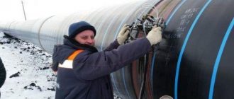
The installation is designed for vacuum testing of the tightness of welded joints and base materials in the oil and gas, energy and other industries. The main types of controlled objects are tanks, boilers, steel and plastic pipelines, fuel tanks, linings and other objects with one-way access. The tightness control unit with a set of vacuum frames is included in the technical equipment list of Transneft PJSC and is approved for use at nuclear industry facilities. Tightness control using the installation is based on the bubble method regulated by PNAE G-7-019-89 and comes down to the following steps:
- Application of a foam-film indicator to the controlled surface;
- Installing a vacuum frame on the controlled surface and creating a vacuum between them;
- Visual control of the flow of bubbles in places where leaks occur.
Features of control using a vacuum installation:
- Conducting inspection without prior preparation of the surface to be inspected;
- Possibility of replacing frames to control products of various shapes;
- Possibility of control immediately after welding;
- Conducting control with one-way access without supplying test pressure;
Scope of delivery:
- vacuum pump made in Russia: NVM-5 (220 V, 1.4 l/s, 9 kg) or vacuum pump made in Italy: SC.8 (220 V, 2.5 l/s, 8 kg);
- vacuum hose - 13 m;
- foam-film indicator – PPI-1;
- installation passport
Depending on the type of surface being monitored, the installation can be additionally equipped with standard vacuum frames or frames made to customer specifications. For a one-time need to use the installation, a leak testing service can be ordered in our NDT laboratory. The work is carried out by certified specialists and a conclusion is issued.
Standard dimensions of vacuum frames are given in the table
| Frame shape | Window dimensions, mm | Photo | Purpose |
| Vacuum frame for tightness control flat | 620x80 | Inspection of butt welds and flat surfaces | |
| Frame for tightness testing, flat-overlapping | 602x62x8 | Control of overlap seams and surfaces with a height difference of 6-10mm | |
| Vacuum corner frame | 530x75 | Inspection of corner (morning) and T-welds | |
| Vacuum corner frame (external) | by application | Inspection of external fillet (morning) welds | |
| Triangular vacuum frame | 195x195x195 | Control of internal welded corners formed by three planes | |
| Vacuum chamber round | Ø 240 | For inspection of flat, convex and concave surfaces | |
| Vacuum chamber rectangular | 230x230 | For inspection of flat surfaces | |
| Vacuum frame for pipes with diameters from 73.6mm to 1220.0mm | Depends on diameter | Pipeline leak testing | |
| Vacuum frame for tightness control, cylindrical | Ø 100 | For external inspection of triangular angles |
Technical characteristics of the vacuum leak detector:
- supply voltage: 220V;
- pump performance: 1.4 l/s;
- maximum vacuum in the frame: -0.07 MPa;
- time to reach maximum vacuum in the frame (in the absence of suction through the seals): no more than 10 s;
- ambient temperature: from -10 to +35 0 C;
- vacuum pump weight: no more than 9 kg
- pump continuous operation time up to 24 hours
Vacuum frames for tightness control
Subscribe to our You Tube
Ultrasonic (UK)
This method is widely used to control the quality of welded joints. As the name suggests, ultrasound is used for testing - a sound wave with a frequency above 20 kHz (for testing it is used from 200 kHz to 100 MHz). Ultrasound propagates throughout the product in the form of waves that have physical parameters such as:
- wavelength;
- period
- frequency
There are a very large number of ultrasonic (acoustic) testing methods.
Within the framework of the article, we will not dwell on each in detail, but will consider the most common method that is used in practice when inspecting welded joints - the ECM method.
Also very important parameters are the types of waves used.
Waves are of the following types:
- Transverse (shear waves).
- Longitudinal (compression waves).
- Surface (Rayleigh).
- Lamb waves.
- Porchhammer waves.
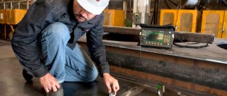
Ultrasonic testing - control
The principle of using ultrasonic testing is as follows: with the help of a flaw detector, ultrasonic vibrations are created and introduced into the product. Ultrasound, spreading in the product and reaching the defect, is reflected from it. If there are no defects, then the sound wave is reflected from the bottom surface. Depending on the return time and signal amplitude, it is possible to determine the depth of the defect and estimate (compare with acceptable) its dimensions.
Preliminary adjustment of the flaw detector is carried out using reference samples (the so-called SOPs - standard samples of the enterprise), on which the maximum permissible defect is artificially created. If during the inspection process a signal greater than the one that was configured on the SOP is detected, then the products are considered defective.
The following equipment is required for ultrasonic testing:
- flaw detector
- Lemo cable
- piezoelectric transducer (PET)
PEPs differ in:
- input - inclined and straight;
- by structure (design) - combined and separated-combined;
- by type of contact with the surface - non-contact and contact.
Inclined probes are used when you need to look for defects that are not parallel to the surface being tested.
Combined probes use one piezoelectric element that both generates and receives signals.
For separate-combined ones, 2 different piezoelements are used, one of which generates a signal, and the other receives it. In this case, the control accuracy increases.
UT - ultrasonic thickness measurement
Ultrasonic thickness gauging is used to determine the thickness of a part with access from one side. It is often used when assessing the residual life, when it is necessary to measure the wall thickness and the amount of wear.
In ultrasonic testing, a separate-combined probe is used, which is connected by a cable to a special device—a thickness gauge. To carry out UT, it is necessary to establish the speed of sound propagation in the material being measured. The adjustment is made on samples with a known thickness made of the same material that will be tested.
The testing process itself is similar to the ultrasonic testing process, only in this case the transducer is not moved, but is simply pressed against the surface at individual measurement points and rotated by 10-15 degrees.
Useful article - Welding lessons for beginners
Vacuum bubble testing of metal structures
The non-destructive testing laboratory of the Olimp IC carries out vacuum-bubble testing of welds, heat-affected zones, and base metal. The service is provided in Moscow and throughout Russia.
NDT specialists can visit the site the next day after receiving the application. Tests and measurements are carried out by employees certified to qualification levels II and III.
Rostechnadzor and other regulatory agencies trust the conclusions on the compliance of the inspection object with the requirements of technical documentation issued by LNK.
The laboratory is certified to carry out vacuum-bubble testing of the following objects:
- building structures;
- pipelines;
- equipment for hazardous industries;
- boiler inspection facilities;
- gas supply systems;
- oil and gas industry equipment;
- lifting structures.
Vacuuming
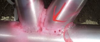
The main and only purpose of the vacuum-bubble method is to detect through defects that affect both the current performance of equipment, for example, maintaining tightness, and its future operation. The presence of defects can cause gradual corrosion of objects, a decrease in their strength and electrical conductivity, as well as emergency situations, leaks of chemicals, and so on. Leak detection is widely used in monitoring welds on tank bottoms. When testing using this method, a vacuum chamber is installed on the side of the welded joint being tested, moistened with a foam indicator solution, in which the air becomes rarefied and, thanks to the resulting pressure difference, atmospheric air penetrates through the through defects, forming bubbles. Control is carried out at ambient temperatures from +8ºС to +40ºС and relative humidity no more than 80%.
The procedure for performing the vacuum-bubble method:
- Remove metal splashes, rust and other contaminants from the surface. It is not allowed to apply paint and varnish coatings before inspection;
- Apply a foaming film composition (FPS) to the controlled surface;
- Place a vacuum chamber on top of the PPS and press tightly;
- Create a vacuum in the vacuum chamber of at least 0.08 MPa;
- Allow exposure for at least 20 seconds;
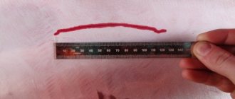
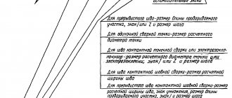
- Inspect the control area located under the frame for indications (foam bubble). If there are indications, mark them next to the vacuum chamber. To do this, it is necessary to visually draw a perpendicular line from the defect relative to the weld. After removing the camera, the markings are transferred to the weld;
- Unload the vacuum system.
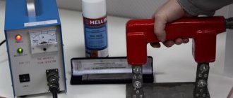
The installation for monitoring should include: a fore-vacuum pump, a vacuum receiver, one or a set of vacuum chambers with three-way valves, vacuum gauges and lighting fixtures, hoses.
The vacuum-bubble method can be used at boiler inspection facilities, gas supply systems, equipment in the oil and gas industry, equipment in fire-explosion and chemically hazardous industries.
The OLIMP IC laboratory offers you high-quality work on vacuum-bubble testing by competent specialists.
The purpose of non-destructive testing using the vacuum-bubble method:
- Establish compliance of the survey object with the requirements of regulatory and technical documentation.
- Give a qualitative and quantitative assessment of surface/subsurface defects, determining the degree of their potential danger.
- To increase the level of safety of equipment operation at industrial facilities classified as particularly hazardous.
- Ensure the safe operation of critical pipelines and prevent possible accidents.
- Timely identify unacceptable structural defects at various stages of construction of buildings and structures.
Mobile laboratory of non-destructive testing "SK "OLIMP" is:
- Guaranteed accuracy of results.
- A complete set of verified equipment, certified materials, calibrated control samples necessary to perform all measurements and tests using non-destructive testing methods using ultrasound within the scope of the laboratory certification. Measuring instruments are included in the state register.
- Years of experience in solving non-standard non-destructive testing problems.
- Competent personnel - employees are certified for qualification levels II and III, NDT specialists have more than 10 years of experience.
- An extensive base of regular customers, each of whom is given a discount the next time they contact or order other services of the company.
We have all the permitting documentation in our possession
Get advice from a laboratory technician or submit an application for vacuum-bubble testing.
- Send a message to e-mail: [email protected]
- Call phone numbers 8, 8 (800) 707-72-31 or request a call back.
Penetrant control
Non-destructive testing, including the capillary method, is an effective, and in some cases the only possible means of preventing emergency situations in high-risk facilities. The task of scientists, design engineers, and process engineers is to develop equipment and testing technology that would enable the flaw detector to identify only serviceable parts and not miss defective ones.
A flaw detector is the last resort that can prevent an accident, failure, or unexpected stop of a machine or mechanism. Particular responsibility lies with flaw detectors who control parts of aviation and space equipment, locomotives and carriages; equipment for nuclear, energy and chemical production, which pose a huge danger not only to humans, but also to the environment.
All over the world, non-destructive quality control and technical diagnostics is a whole industry, an integral part of the production and operation of all technical devices: hundreds of thousands of specialists every day ensure the rejection of low-quality parts during production (quality) and the timely detection of dangerous cracks on working technical devices (diagnostics), before everything dangerous to life, human health and the environment (safety).
The level of development of the advanced countries of the world at the present stage is characterized not so much by the high volume of production and range of products, but by indicators of quality, reliability and safety.
In highly developed countries, quality control costs average 1–3% of the cost of manufactured products, and in industries such as defense, nuclear, and aerospace, quality control costs increase to 12–18%. Labor costs for monitoring welded joints in the construction of large-diameter and long-distance pipelines reach 10%. The whole world has long understood that savings on control are imaginary savings, which ultimately result in huge costs for overcoming the consequences of accidents and disasters.
At the manufacturing stage, objective information is needed about the properties of the part, which makes it possible to judge the quality of the part, its suitability for work and the competitiveness of the product as a whole.
The use of non-destructive testing means during operation makes it possible to diagnose the technical condition of an object, determine its residual life, and the terms of further safe operation. Diagnostics is especially relevant for such potentially dangerous technical objects as equipment of main oil and gas pipelines, chemical and oil refining plants, pressure vessels, lifting and transport devices, etc., especially if we take into account that many of them have already exhausted their service life.
Judgment about performance and quality is achieved through identifying using non-destructive testing and technical diagnostics devices:
- surface and internal defects in the continuity of material, parts and structural elements (cracks, cavities, pores, delaminations, etc.);
- unacceptable changes in the structure of the material and physical and mechanical properties (grain size, density, elastic and strength characteristics, hardness, internal stresses, humidity, etc.);
- deviations of geometric parameters (thicknesses of coatings, surface-hardened layers, wall thicknesses of parts and structural elements, etc.);
- internal structure of objects (introscopy).
Acoustic emission
The acoustic emission testing method provides excellent results for detecting defects at an early stage. This method, together with other non-destructive testing methods, provides comprehensive data.
It is based on recording signals arising from structural and structural changes. In simple terms, this method monitors any changes in the structure due to sensors attached to the structure or equipment. That is, when defects occur (corrosion, cracks, delaminations, etc.), sensors record this and convert it into an electrical signal. The signal is processed through a multi-channel system and converted into data, which is directly processed and determines the location of the defect.
In this way, it is possible to track changes in the state of structures and equipment, but it is impossible to accurately determine the parameters of the detected defect. This method is best used in conjunction with ultrasonic or radiographic testing methods.
Leak detection using bubble vacuum method (vacuum) (PVT)
Penetrant control (PVC)
6.2.9.1 PVC is carried out to identify surface defects in welded joints and base metal of tank structural elements.
Flaw detection materials are used in the form of sets in aerosol packages according to the instructions for use. Kits should include:
- indicator penetrant, the characteristic color tone of which can be observed in visible radiation;
— cleaner of the test object from penetrant;
— developer of an indicator trace of a defect.
Compatibility of materials in sets is required. The compositions of the kit must not cause corrosion.
6.2.9.2 PVK is carried out in accordance with GOST 18442 (IV sensitivity class), instructions for the use of flaw detection materials and includes:
a) applying an indicator penetrant to the test surface, which includes the weld and the base metal at a distance greater than the thickness of the test elements on both sides of the seam. The penetrant is not allowed to dry on the surface;
b) removal of indicator penetrant;
c) application and drying of the developer. Drips and leaks of developer are not allowed. Drying of the developer should be carried out by natural evaporation or by blowing with heated air at a temperature of plus (60±10) °C;
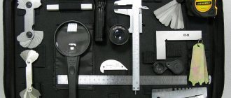
d) inspection of the controlled surface is carried out 20 minutes after the developer has dried under illumination of at least 350 Lux. When inspecting the controlled surface, magnifying glasses from 2 x to 7 x magnification are used. If an indicator trace is detected, the identified defect is assessed using VIC. To do this, the area with the mark is marked and the surface to be inspected is cleaned of flaw detection materials. VIC is carried out using magnifying glasses and optical measuring instruments with tenfold or more magnification;
e) the scope of control of pontoons made of aluminum alloys is determined based on the results of the visual inspection, and all areas of the pontoon (seams and base metal) on the outer surface of which the presence of oil is detected must be inspected;
f) the results of the PVK are formalized in accordance with Appendix E.
6.2.10.1 PVT is used to detect through damage (tightness violations) of welded joints of tank structural elements in accordance with GOST 3242.
To carry out leak detection of PVT, vacuum chambers must be used that ensure the creation of a vacuum of at least 0.08 MPa.
6.2.10.2 When carrying out HTP, a vacuum must be created in the chamber for welded joints with the thickness of the elements being connected:
- no more than 4 mm - no less than 0.067 MPa;
- more than 4 mm - not less than 0.08 MPa.
6.2.10.3 Control is carried out in accordance with the operating instructions for the vacuum chamber.
6.2.10.4 During leak detection, foam indicators must be used to ensure leak detection at the evacuation temperature.
6.2.10.5 A leak is determined by the appearance of foam indicator bubbles.
6.2.10.6 HTP is not carried out through a particularly reinforced coating. HTP on damaged coatings of all types that do not meet the requirements of RD-23.020.00-KTN-184-10 is carried out after removing the remaining coating and stripping the structures to metal.
HTP through normal and/or reinforced coatings is carried out according to the results of the VIC.
6.2.10.7 The results of the HTP are drawn up in accordance with Appendix Y. The HTP report is accompanied by sketches of the tank structures indicating the coordinates of the location of the identified through damage (tightness violations).
Date added: 2015-06-04; ; Copyright infringement?
Your opinion is important to us! Was the published material useful? Yes | No
8.1. General requirements
8.1.1. In the manufacture and installation of tanks, the following electric arc welding methods are used:
- mechanized arc welding with a consumable electrode in shielding gas;
- automatic submerged arc welding;
- mechanized arc welding with self-shielding flux-cored wire;
- mechanized arc welding with self-shielding flux-cored wire in a protective gas environment;
- manual arc welding.
8.1.2. Contracting organizations (manufacturer and installer) develop operational flow charts for welding and inspection of welded joints. Technological processes of factory and installation welding must provide parameters of welded joints in accordance with the requirements of KM and PPR projects and this standard for physical and mechanical characteristics, geometric dimensions, limit parameters and types of defects (see 5.2.1.8, 5.2.3, 8.1.6 , 8.1.7, 8.1.9.2, 8.2). Supervision of welding work and welding of metal structures of tanks must be performed by specialists certified in accordance with [16].
8.1.3. Factory welding of tank structures should be carried out in accordance with an approved technological process, which should include:
- requirements for the shape and preparation of edges of welded parts;
- welding methods and modes, welding materials, sequence of technological operations;
- instructions for preparing and assembling parts before welding using jigs.
8.1.4. Assembly welding of structures is carried out in accordance with the instructions of the PPR, which must provide for:
- the most effective methods of welding installation joints;
- welding materials;
- form of preparation of welded elements;
- technological welding modes;
- necessary technological equipment and equipment;
- instructions on climatic (temperature, wind, humidity) conditions for performing welding work.
8.1.5. The welding materials used and the requirements for their storage conditions must comply with the standards or specifications for the supply of welding materials. Welding materials and welding technologies must be certified according to [17] - [19].
8.1.6. Methods and modes of welding structures must ensure:
- the level of mechanical properties and cold resistance of welded joints provided for in the design documentation;
- level of defects not exceeding the requirements of this standard (see 8.2, 8.3).
8.1.7. The shape factor of the weld weld (passage) must be in the range from 1.3 to 2.0. It is allowed to perform intermittent welds in one pass in off-design connections of tank elements that do not affect their tightness.
8.1.8. Temporary technological parts welded to the tank during the manufacture of elements and installation and subject to removal must be removed without impact on the elements of the tank, and the remains of the welds must be cleaned flush with the base metal and checked.
8.1.9. Requirements for mechanical properties of welded joints
8.1.9.1. The mechanical properties (except hardness) of the metal of corner, lap and T-joints are determined on samples cut from prototype butt welded joints. Prototype butt joints must be made using steel grades, welding materials and equipment intended for welding the above types of joints.
8.1.9.2. Requirements for strength characteristics
The metal of welded joints must be of equal strength to the base metal. Tests should be carried out on three samples of type XII or XIII in accordance with GOST 6996. The metal of the weld joint between the wall and the bottom (morning weld) is subject to an additional requirement of equal strength with the base metal according to the standard value of the yield strength.
8.1.9.3. Requirements for impact strength of welded joints
The impact strength at the specified test temperature must be no less than the values specified in 5.2.3. The test temperature is set in accordance with the requirements of 5.2.3.2. Impact bending tests (impact toughness) should be carried out for the weld metal and the heat-affected zone of butt joints of elements of groups A and B. In this case, the impact toughness of the weld metal and the heat-affected zone (HAZ) is determined on three transverse samples (three samples along the seam ; according to the HAZ - three samples) with a sharp notch of type IX (for a base metal thickness of 11 mm or more) and type X (for a base metal thickness of 6 - 10 mm) according to GOST 6996.
8.1.9.4. Requirements for technological bending tests of welded joints
When testing welded joints for static bending, the arithmetic mean value of the bending angle of six transverse samples (type XXVII according to GOST 6996) must be at least 120º, and the minimum value of the bending angle of one sample must not be less than 100º. When the thickness of the base metal is up to 12 mm inclusive, tests are carried out by bending the sample with the root of the weld inward (on three samples) and the root of the weld outward (on three samples), and when the thickness of the base metal is more than 12 mm - by bending the samples “on edge” (on six samples ).