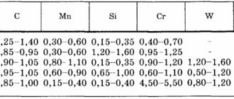
Steel products used to create building structures during operation experience significant tensile, compressive stresses, and sudden mechanical impacts. The applied forces can be either static or dynamic. To ensure the strength and durability of the structure, it is necessary to use metal products with mechanical characteristics that correspond to the planned operational loads. Tensile tests are one of the most common methods for determining the grade of steel or resolving controversial issues when investigating the causes of emergency situations and accidents.
Characteristics determined by static tensile tests
Research is carried out in testing machines with manual or hydraulic drive. The second option provides the ability to create much more power. Based on the research results, a stretch diagram is drawn up.
During mechanical static tensile tests, carried out in accordance with GOST 1497-84, a set of steel properties is determined.
Strength characteristics
- The limit of proportionality is Ϭп . Characterizes the voltage above which Hooke's law ceases to operate. After hardening of the metal, which, for example, is carried out during cold deformation, Ϭп increases by 1.5-1.8 times.
Definition! Hooke's law states that the deformation generated in an elastic body is directly proportional to the applied force.
- Yield strength – Ϭт . This is the load at which the deformation increases under constant stress. A clearly horizontal area present on the diagram may be absent. In this situation, a conditional Ϭt is established, at which the residual deformations are approximately equal to 0.2%.
- Ultimate strength (temporary tensile strength) – Ϭв . This is the maximum force at which the sample does not break. Exceeding it will lead to rupture of the rod.
- Break stress – Ϭр . When testing for strength, two types of rupture stress are determined - conditional and true.
Elasticity characteristics
- Elastic limit – Ϭу . Corresponds to a load at which the permanent elongation is 0.05%. The values of Ϭу and Ϭп in the diagram are nearby, so Ϭу is established through very detailed research.
Plasticity characteristics
- Relative permanent elongation . Determined by the formula Δ=(L1-L0)*100% / L0, in which L0 is the initial length of the sample, L1 is the calculated length after the end of the research.
- Relative residual narrowing . Ψ=(A0-Ash)*100% / A0, A0 is the cross-sectional area of the rod before testing, Ash is the cross-sectional area of the neck.
Test methods for mechanical properties
Mechanical properties characterize the ability of a material to resist deformation and destruction under the influence of applied loads.
According to the nature of the change in time of the current load, mechanical tests can be static (tensile, compression, bending, torsion), dynamic (impact bending) and cyclic (fatigue).
Based on the effect of temperature on the process, they are divided into tests at room temperature, low temperature and high temperature (for long-term strength, creep).
Static tests are carried out when a sample is exposed to a constant load at a certain speed. The strain rate ranges from 10-4 to 10-1 s-1. Static tensile tests are among the most common. The properties determined by these tests are given in numerous material specification standards. Static tests include tensile, compression, bending, and torsion tests.
Dynamic tests are characterized by the application of an impact load and a significant strain rate to the sample. The duration of the test does not exceed hundreds of fractions of a second. The strain rate is about 102 s-1. Dynamic tests are most often carried out using the impact bending scheme of notched samples.
Cyclic tests are characterized by repeated load changes in magnitude and direction. An example of tests are fatigue tests; they are long-term and their results determine the number of cycles until failure at different stress values. Ultimately, the ultimate stress is found that the sample can withstand without failure for a certain number of loading cycles.
Hardness tests.
The simplest mechanical property is hardness. Methods for determining hardness, depending on the speed of application of the load, are divided into static and dynamic, and according to the method of its application - into indentation and scratching methods. Methods for determining hardness according to Brinell, Rockwell, Vickers are static testing methods.
Hardness is the ability of a material to resist being pressed into it by a harder body (indenter) under the influence of external forces.
When testing for hardness, a pyramid, cone or ball (indenter) is pressed into the surface of materials, and therefore the test methods are distinguished according to Vickers, Rockwell and Brinell, respectively. In addition, there are less common hardness testing methods: the elastic rebound method (Shore), the comparative hardness method (Poldi) and some others.
When testing materials for hardness, standard special samples are not made, but certain requirements are imposed on the size and surface of samples and products.
Vickers hardness (GOST 2999-75) is established by pressing an indenter into the metal - a diamond pyramid with an apex angle of 136° under the influence of a constant load P: 1; 2; 2.5; 3; 5; 10; 20; thirty; 50 or 100 kgf and holding under load for 10-15 s. To determine the hardness of ferrous metals and alloys, loads from 5 to 100 kgf are used, copper alloys - from 2.5 to 50 kgf, aluminum alloys - from 1 to 100 kgf. After removing the load, the length of the diagonal of the imprint is found using a microscope of the device, and the hardness HV is calculated using the formula
HV = 1.854*P/d2
where P is load, kgf; d - imprint diagonal, mm.
There is a table of the dependence of hardness on the magnitude of the load and the length of the diagonal. Therefore, in practice, calculations are not performed, but a ready-made calculation table is used. Vickers hardness HV is measured in kgf/mm2, N/mm2 or MPa. The Vickers hardness value can vary from HV2060 to HV5 at a load of 1 kgf.
Brinell method, a hardened steel ball with a diameter of 10, 5 or 2.5 mm is pressed into a sample or product under loads of 3000, 1000, 750, 500, 250, 62.5 kgf, etc. (GOST 9012-59, Fig. 1. ). The resulting round imprint on the sample is measured under a magnifying glass and the Brinell hardness value is found from the tables, the value of which does not exceed 450 HB. Brinell hardness is almost identical to Vickers hardness values.
NV hardness is also the magnitude of the indentation resistance stress:
HB=P/Fot=P/πDt=2P/πD(D-√(D2-d2))
where P is load, kgf;
Fot - print area, mm2;
t is the depth of the print segment;
D - ball diameter, mm;
d - imprint diameter, mm.
Brinell hardness HB (by default) has the dimension kgf/mm2, for example, the hardness of an aluminum alloy is 70 HB. For a load defined in Newtons, Brinell hardness is measured in MPa. For example, the hardness of annealed steel is 207 HB at a load of 3000 kgf, a ball diameter of 10 mm, an indentation diameter of 4.2 mm, or, taking into account the conversion factor: 1 N = 9.8 kgf,
HB = 2,028 MPa.
Rice. 1. Scheme for determining Brinell hardness
Rockwell method (GOST 9013-59), a diamond cone with an apex angle of 120° (scales A and C) or a steel ball with a diameter of 1.5875 mm (scale B) is pressed.
In this case, the hardness is determined, respectively, HRA, HRC and HRB. Currently, Rockwell hardness measurement is the most common method, because when using Rockwell hardness testers, there is no need to measure the indentation; the hardness number is read from the instrument scale immediately after the main load is removed.
The method consists of pressing an indenter into the test sample under the influence of two sequentially applied loads - preliminary P0 and main P1, which is added to the preliminary load, so that the total load P = P0 + P1. After holding for several seconds, the main load is removed and the residual penetration depth of the indenter is measured. which at the same time continues to be under the influence of preload. The movement of the main arrow of the indicator by one scale division corresponds to the movement of the indenter by 0.002 mm, which is taken as a unit of hardness.
In Fig. Figure 2 shows a diagram of hardness measurement using the Rockwell method using a diamond or carbide cone. During testing, the depth of the restored indentation is measured. Scales A and C coincide with each other, since the tests are carried out with the same indenter - a diamond cone, but at different loads: 60 and 150 kgf, respectively. Hardness in this case is defined as
HRC= t/0.002=100-(Hh)/0.002
On scale B (load 100 kgf, ball)
HRB = 130-(Hh)/0.002
Rice. 2. Scheme for determining Rockwell hardness (indenter - cone)
In practice, Rockwell hardness values are not calculated using formulas, but are read from the corresponding (black or red) scale of the device. HRC and HRA scales are used for high hardness, HRB for low hardness. The Rockwell hardness number is measured in arbitrary units; it is a measure of the depth of indentation of an indenter under a certain load.
Tensile testing of materials is carried out in accordance with GOST 1497-84 “Methods of tensile testing”. The standard establishes methods for static tensile tests of ferrous and non-ferrous metals to determine at a temperature of 20 °C the limits of proportionality, elasticity, fluidity, tensile strength, relative elongation and relative contraction, and elastic modulus.
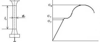
For testing, flat and cylindrical samples cut from a part or specially made are used. The dimensions of the samples are regulated by the specified standard; they are subject to geometric similarity and can be short or long. For a cylindrical sample, the ratio of the initial working length l0 and the initial diameter d0 is taken: l0= 5d0 - short sample, l0= 10d0 - long sample. For a flat sample, the ratio of the working length l0 and the cross-sectional area F0 is taken:
l0= 5.65√F0 - short sample, l0= 11.3√F0 - long sample. Cylindrical samples are made with a diameter of 3 mm or more. The samples consist of a working part of length l0 and heads, the shape and size of which correspond to the grips of the machine (Fig. 3).
Rice. 3. Cylindrical and flat samples before (a) and after (b) tensile testing
The stretching of the sample is carried out on special machines that make it possible to record the magnitude of the applied load and the change in the length of the sample during stretching. These same machines make it possible to record the change in sample length with increasing load (Fig. 4), i.e. primary tensile test diagram in coordinates: load P, N, kN; and absolute elongation of sample A, mm.
Rice. 4. Primary stretch diagram
By measuring the load at characteristic points of the tensile test diagram (Fig. 4), the following parameters of the mechanical properties of materials are determined:
σ pc - limit of proportionality, point p;
σ 0.05—elastic limit, point e;
σ t—physical yield strength, point s;
σ 0.2 - conditional yield strength;
σ in - temporary tensile strength, or tensile strength, point b.
The values 0.05 and 0.2 in the recording of the elastic and yield strength correspond to the value of the residual strain ∆l as a percentage of l0 when the sample is stretched. Tensile test stresses are calculated by dividing the load P corresponding to the characteristic point on the diagram by the initial cross-sectional area F0 of the working part of the test sample:
σpc=Ppc/F0; σ0.05=P 0.05 / F0; σт=Pт/F0, or σв=P max/F0;
The cross-sectional area F0 is determined by the following formulas:
for a cylindrical sample
F0 = πd02/ 4
for flat sample
F0 = a0*b0
where a0 is the initial thickness; b0 is the initial width of the sample.
At point k, the fracture resistance stress of the material is set.
The proportionality limit and the elastic limit are determined using a strain gauge (a device for determining the amount of deformation). The physical and conditional yield strength is calculated by finding the load from the tensile diagram. If there is no yield area on the diagram, then to calculate the conditional yield strength it is necessary to draw graphical plots on the diagram (Fig. 1.5). First, find the residual strain value equal to 0.2% of l0, then mark a segment on the strain axis equal to 0.2% of l0, and draw a line parallel to the proportional section of the tensile diagram until it intersects with the tensile curve.
Rice. 5. Determination of yield strength
The load P0.2 corresponds to the point of their intersection. Physical and conditional yield strength characterize the ability of a material to begin plastic deformation, i.e. resistance to small plastic deformation.
The tensile strength can be calculated using the readings of a force meter, based on the maximum load Pmax at break, or find Pmax (Pv) using the primary tensile diagram. The nature of tensile deformation of ductile and brittle materials differs significantly.
Brittle materials, after reaching the maximum load, quickly collapse without significant plastic deformation, therefore σв for
for brittle materials it is a characteristic of resistance to fracture, and for plastic materials it is a characteristic of resistance to deformation.
The fracture stress is defined as true. In this case, the fracture load is divided by the final cross-sectional area of the sample after fracture FK:
Sk=Pk/Fk
All values calculated in this way are characteristics of the strength of the material.
Plasticity , i.e. the ability to deform without destruction is characterized by changes in the dimensions of the sample. When testing tensile strength, the following plasticity characteristics are determined:
relative extension
δ=(lk-l0)/ l0*100%
relative narrowing
Ψ=(F0к-F)/ F0*100%
where lк, Fк are, respectively, the length of the working part and the cross-sectional area of the sample after rupture.
The calculated characteristics of the mechanical properties after the tensile test are recorded in the protocol.
Impact bending tests.
Impact strength characterizes the specific work expended on fracture upon impact of a notched sample. Impact strength is tested on a pendulum impact driver with a constant pendulum operating reserve in accordance with GOST 9454-78 “Metals. Test method for impact bending at low, room and elevated temperatures." The standard applies to ferrous and non-ferrous metals and alloys and establishes a test method at temperatures from -100 to +1000 °C. The method is based on the destruction of a sample with a stress concentrator by the impact of a pendulum impact driver. As a result of the test, the total work expended during impact K, or the impact strength KS, is determined.
Rectangular-shaped samples with a U, V, T type concentrator (fatigue crack) are used. The most common samples are 55x10x10 mm samples with a 2x2 mm U-concentrate (Fig. 6).
Rice. 6. Standard specimen with U -notch for impact testing
Only part of the pendulum's energy is expended to destroy the sample by impact, and therefore the pendulum, after destruction of the sample, continues to move, deflecting at a certain angle. The greater the amount of work expended on the destruction of the sample, the smaller the angle it deviates from the vertical after destruction. The magnitude of this angle is used to determine the impact work K or the work expended on the destruction of the sample. The work of destruction K is related to the cross-sectional area of the sample So at the fracture site and thereby KS is found - impact strength:
KC = K/S0,
where K is measured in J (kgf*m), S0 is measured in m2 (cm2).
Depending on the type of concentrator, impact strength is indicated
KCU, KCV, KST and has the dimension MJ/m2 (MJ/cm2) or kgf*m/cm2.
Standard samples for static tensile tests
To carry out the tests, samples of round or rectangular cross-section are made. Standards regulate both sample sizes and mechanical processing methods. The main conditions are uniformity of dimensions along the length, alignment, well-treated surface, which should be free of scratches and cuts. Roughness is standardized.
Length of round cross-section specimens:
- short – 4-5 diameters;
- normal - 10 diameters.
Most often, samples with diameters of 6, 10, 20 mm are made. Before testing begins, samples are measured in two mutually perpendicular directions in three places. Measurement accuracy – 0.5 mm. The width and thickness of flat samples are measured at the edges and in the center of the measured plane. The cross-sectional area is determined with an accuracy of 0.5%. The accuracy of measuring the sample length is 0.1 mm.
Dynamic testing of steel samples
The main type of such research is bending tests carried out in accordance with GOST 9454-78. With this type of analysis of steel samples, the law of similarity is irrelevant, so samples with dimensions and shape of the notch that strictly comply with the standards are used. The main sample has a square cross-section with an area of 10x10 mm and the following types of cuts:
- U-shaped (Charpy samples) – located in the middle of the rod. Such samples are used to establish standards for bars that will receive a V-notch.
- V-shaped (Menage samples) . The main type of steel rods used for researching materials that will be used in critical structures.
- With T-shaped hub . There are several options for rod sizes. Such samples are used in studies of alloys intended for use in structures in which resistance to crack growth is important.
As a result of dynamic bending tests, the value of impact strength is calculated - a characteristic that depends on the combination of strength and plastic properties of steel. The higher it is, the more reliable the material works under dynamic loads.
All steels, products from which are intended for use under dynamic loads, are subjected to impact bending tests. Depending on the planned operating conditions, impact strength is determined at normal, reduced or elevated temperatures.
Methods for determining the strength of a structural material
Conducting static strength tests is testing template samples of a certain shape. Based on the results of the experiments, experts draw a diagram on which you can clearly see how the material deforms under stress. Graphic data helps to evaluate the elastic and yield limits, and temporary resistance. To determine the parameters of a particular material, special calculations are carried out to calculate the fatigue load and ultimate stress.
Methods for determining the strength of a material depend on its variety and type of building structure. For example, a standard way to evaluate the performance of a brick is to test the compression of two whole bricks that are stacked on top of each other. Ultrasonic techniques are used to study sand-lime brick.
All research methods can be divided into two large groups - destructive and non-destructive testing. They apply to individual building structures, specimens and individual elements.
Whenever possible, experts try to give preference to non-destructive testing methods that do not require dismantling and disassembling the structure. Although samples are taken from the least important functional elements, standard strength testing methods affect the stability and reliability of the building. But it is not always and not possible to assess the strength of all construction products using non-destructive testing methods.
Destructive testing methods
A distinctive feature of this type of research is testing on control samples until they are completely destroyed. For example, a brick can be compressed or otherwise influenced from the outside until it cracks or crumbles. To do this, part of the material is removed from the structure and sent to the laboratory to evaluate the strength characteristics.
To determine the sampling site, the accessibility of the sample, the degree of load and damage, and the intensity of operation of the building structure are taken into account. Destructive testing methods make it possible to calculate the physical properties of the sample with minimal error. But they require serious labor. The main disadvantage of destructive testing is the need to violate the integrity of the building. This is not always possible, so experts try to evaluate the characteristics of building materials using non-destructive testing.
Non-destructive testing methods
Research using non-destructive methods is actively used in the technical examination of residential, industrial, administrative buildings and structures, objects of historical and cultural heritage. They can be based on various technologies:
- mechanical: the elastic rebound method, the study of plastic deformations and impact impulse are often used to examine concrete;
- radiation: methods are based on the use of radioisotopes and neutrons;
- magnetic: methods of magnetic particle and induction assessment;
- acoustic: research by exposure to ultrasound, assessment of the effects of acoustic emission;
- radio wave: study of the distribution of waves of different lengths in a material;
- electrical: determination of characteristics through calculation of electrical resistance, electrical inductance and electrical capacity of a building material.
With the help of modern instruments and technology, it is possible to determine the strength characteristics of a product without design changes and maintain the original physical and mechanical parameters of the materials.