Preface
- 1 PREPARED by the Limited Liability Company “National Expert Diagnostic) on the basis of its own translation into Russian of the English version of the standard specified in paragraph 4
- 2 INTRODUCED by the Technical Committee for Standardization TK 364 “Welding and related processes”
- 3 APPROVED AND ENTERED INTO EFFECT by order of the Federal Agency for Technical Regulation and Metrology dated March 31, 2022 No. 237-st
- 4 This standard is identical to the international standard ISO 13920:1996 “Welding. General tolerances for welded structures. Linear and angular dimensions. Shape and location" (ISO 13920:1996 "Welding - General tolerances for welded constructions - Dimensions for lengths and angles - Shape and position", IDT).
This International Standard was developed by Technical Committee for Standardization ISO/TC 44, Welding and related processes, subcommittee SC 10.
When applying this standard, it is recommended to use, instead of reference international standards, the corresponding national standards, information about which is given in the additional appendix YES
- 5 INTRODUCED FOR THE FIRST TIME
The rules for applying this standard are established in Article 26 of the Federal Law of June 29, 2015 Ns 162-FZ “On Standardization in the Russian Federation”. Information about changes to this standard is published in the annual (as of January 1 of the current year) information index “National Standards”, and the official text of changes and amendments is published in the monthly information index “National Standards”. In case of revision (replacement) or cancellation of this standard, the corresponding notice will be published in the next issue of the monthly information index “National Standards”. Relevant information, notices and texts are also posted in the public information system - on the official website of the Federal Agency for Technical Regulation and Metrology on the Internet (www.gost.ru)
© Standardinform, 2017
This standard cannot be fully or partially reproduced, replicated or distributed as an official publication without permission from the Federal Agency for Technical Regulation and Metrology
Methods for calculating the length of the weld and other connection parameters
When calculating the length of the weld, it is first necessary to eliminate or minimize the parameter errors that affect the strength of the joint. First of all, it is an indicator of compression and tension of the metal. To determine this process you need a formula:
Where:
Yс
– coefficient showing workplace conditions. This indicator is considered generally accepted and can be found in the corresponding tables. It is necessary to substitute the desired indicator into the formula.
Rу
– metal resistance index, which takes into account its fluidity. It can be found in specialized reference books.
Ru
– the second indicator of metal resistance. It can be found in reference books.
N
– indicator of the maximum permissible load on the joint.
T
– the value of the thinnest wall thickness of the parts being welded.
Lw
— maximum length of the weld. When calculating, this parameter must be reduced by 2t.
Rwу
– resistance, which depends on the maximum strength of the connection.
When welding different metals, it is necessary to take the Ru and Ry indicators of the metal that will be less durable. Do the same when you need to calculate the length of the weld for shear.
When developing metal structures, the main thing is to take into account not only the requirements and safety standards of the welded joint, but also its permissible load level. If it is necessary to create several welded joints, it is important to distribute them correctly. The welding load must be distributed evenly between each joint.
The connection parameters are calculated using mathematical calculations. If the final result turns out to be unsatisfactory and unsuitable, then changes must be made to the design and then recalculated.
The permissible length of the weld seam for tearing is determined taking into account the force directed towards the center of gravity. A section with a high degree of danger is selected and calculations are made using this formula:
The type of metal in this case will not affect the strength of the seam, but each indicator presented in the formula will. In it:
N
– the maximum indicator of force exerting pressure on the joint.
ßf, ßz
– coefficients from reference tables, the value of which will not depend on the type of metals being welded. Typically, ßz = 1 and ßf = 0.7.
Rwf
– shear resistance value. This indicator is taken from reference books and GOST tables.
Rwz
– resistance indicator along the weld line. Values can be found in reference books.
Ywf
– correction factor, the indicator of which depends on the resistance of the metal. For example, if for metal the indicator is 4,200 kgf/cm², then the correction factor will be equal to 0.85.
WITH
– coefficient indicator of working environment conditions. The corresponding values can be found in the reference book.
Kf
– thickness of the joint along the fusion line.
Lw
– total joint length reduced by 10 mm.
In lap joints, the position in space and the type of welded joint are taken into account, since the joint itself can be either corner, flank, or frontal. The calculations made make it possible not only to obtain data on the minimum permissible welding area, but also indicators regarding the design strength of the joint lines.
To calculate the welding area, the height of the conditional triangular seam is taken as the base. In manual welding, this figure will be equal to 0.7, provided that the legs are equal. If the work is performed by automatic or semi-automatic devices, the degree of heating of the metal will be greater, and the coefficient will change accordingly. Indicators must be taken from reference tables.
STRUCTURAL ELEMENTS OF WELDED JOINTS IN MANUAL ARC WELDING
Due to the importance of proper preparation of welded edges from the point of view of quality, efficiency, strength and performance of the welded joint, state standards have been created for the preparation of edges for welding. The standards regulate the shape and structural elements of cutting and assembling edges for welding and the dimensions of finished welds.
GOST 5264-80 “Seams of welded joints. Manual electric arc welding. Basic types, structural elements and dimensions" and GOST 11534-75 "Manual arc welding. Welded connections at acute and obtuse angles. Basic types, structural elements and dimensions” regulate the structural elements of edge preparation and the dimensions of the seams made during manual arc welding with a metal electrode in all spatial positions.
It is necessary to note some features of the application of standards. Due to their technological features, various methods of electric fusion welding make it possible to obtain different maximum penetration depths. By varying the basic parameters of the welding mode and the design types of edge preparation, it is possible to increase or decrease the depth of penetration and other dimensions of the weld.
For this reason, the mentioned standards regulating the structural elements of edge preparation take into account the possibility of varying the welding current, voltage, electrode wire diameter (current density) and welding speed. In cases where the welding process requires the use of high currents, high current densities and heat concentrations, increased bluntness, smaller groove angles and gap sizes are possible.
In manual arc welding, factors such as welding current, welding speed and arc voltage vary within small limits.
To ensure through penetration of the edges of the product when welding one-sided butt or fillet welds with sheet thicknesses over 4 mm, welding must be carried out along pre-cut edges. When manually welding, welders cannot significantly change the depth of penetration of the base metal, but by changing the amplitude of the transverse vibrations of the electrode, they can significantly change the width of the weld.
For sheet thicknesses of 9 - 100 mm, GOST 5264-80 for butt joints requires mandatory cutting of edges and a gap, which vary in size depending on the thickness of the metal and the type of joint.
In all cases, using edge preparation standards, you should choose those types of grooves that provide the least volume and cost of edge preparation work, volume and weight of deposited metal, full thickness penetration, smooth mating shape of the outer part of the weld and minimal angular deformations.
The quality of welded joints and the efficiency of the welding process are greatly influenced by the cleanliness of the edges and the adjacent surface of the base metal, the accuracy of edge preparation and assembly for welding. Blanks for parts to be welded should be made from pre-straightened and cleaned metal. Cutting of parts and preparation of edges is carried out by mechanical processing (on press shears, edge planers and milling machines), oxygen gas and plasma cutting, etc. After using thermal cutting methods, the edges are cleaned of burr, scale, etc. (grinding wheels, metal brushes, etc. etc.).
In some cases, when welding high-alloy steels, the base metal in the heat-affected zone after cutting is also removed mechanically. Before assembling the edge, adjacent areas of the base metal (40 mm from the edge) must be cleaned of oil, rust and other contaminants using wire brushes, shot blasting or chemical etching. The parts are assembled using tack welds (short seams) 20-30 mm long or in special assembly devices.
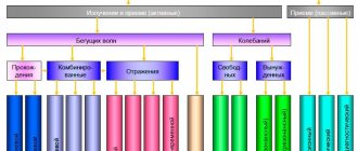
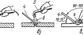
Influence of welding speed and mode
There is a dependence of the weld cross-section configuration on the process parameters:
- As the current increases at a constant voltage, the temperature increases, so the penetration depth becomes greater. But with excessive amperage, metal can be burned.
- An increase in voltage at a constant current leads to an increase in the length. If there is an excess, lack of penetration is possible.
- As the speed of movement of the electrode increases, the heating temperature of the metal decreases. The seam width and penetration depth are reduced. At speeds above 50 m/h, the lack of temperature leads to the formation of defects that make the seam weak.
- The viscosity of the electrode material affects the shape of the amplification. The higher it is, the more convex the surfacing becomes.
We recommend reading: What are the types of defects in welds?
The welding mode is selected according to the workpiece with the smallest thickness, so as not to burn through it.
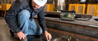
Correct setting of the welding machine
The operating mode is determined by 3 parameters:
- tension;
- current strength;
- speed of electrode movement.
Setting up the device consists of selecting their optimal values.
The following factors influence this:
- Workpiece thickness.
- Material.
- Type of seam.
The parameters are selected experimentally, acting in the following sequence:
- Take an unnecessary fragment from the same material as the workpieces that need to be welded.
- Clean it with a grinder to a metallic shine.
- Set the voltage on the machine to 15-20 V and the welding current to 100 A.
- Light the arc and, by gradually adjusting the parameters, achieve stable combustion with good penetration depth.
- Record the optimal settings in writing or by taking photographs.
- Smoothly reduce the current until the arc goes out. Record the amperage at which this occurred.
- Return the regulator to 100 A, ignite the arc again and increase the current to the highest value. He is also recorded.
- Reduce the voltage by 0.5 V and determine the minimum and maximum current in the same way. Repeat this action several times, each time reducing the voltage.
- Return to optimal settings.
- In the same order, determine the upper and lower current limits, increasing the voltage several times in 0.5 V increments.
We recommend reading: How welds are shown in the drawings
Points 6-10 of the instructions allow you to determine the extreme points of the range within which the device can be adjusted before working with other workpieces.
When setting up a semi-automatic machine, the feed rate of the filler rod is selected depending on the current strength: the greater the amperage, the faster the material should flow.
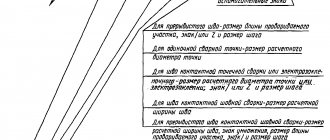
Geometric characteristics
As mentioned above, the geometry of the seams depends on the type of connection. The main geometric dimensions of the sections of butt and fillet welds are presented in the following figure:
Geometric characteristics
- where S is the thickness of the parts;
- e – width of the weld;
- g – convexity;
- m – concavity;
- h – penetration depth;
- t – weld thickness;
- b – gap in the connection;
- k – fillet weld leg;
- p – height;
- a – thickness.
Types of seams and joint geometry
The connected parts are oriented relative to each other in different ways.
Depending on this, there are 3 types of seams:
- Stykova. The parts are located in the same plane, the ends of their walls abut one another.
- Overlapping. The seam is used with the same arrangement of parts, if their small thickness (less than 8 mm) does not allow the use of the butt option. The elements are placed one on top of the other with an overlap of 2 mm and welded on both sides along the edge.
- Angular. It is used in cross-shaped, L- and T-shaped joints. Parts may be positioned at a deviation from a right angle, for example, a cross-shaped connection of the form “X” instead of “+”.
We recommend reading: How to weld fillet welds
There are frontal and flank lap joints. The first is performed by welding the applied part along the end edge, the second - along the side edges on both sides.
Weld parameters.
In addition to the leg, the geometry of the weld is characterized by a number of parameters.
The main ones are:
- Width. Maximum horizontal size.
- Height. The same goes vertically.
- Convexity or concavity. Distance from the surface of the parts to the highest point of deposition.
- Penetration depth. The vertical distance from the surface of the parts to the bottom point of the molten metal.
The deep part of the seam is called the root. It is adjacent to unmolten metal. Boiling the root is the most critical stage when joining massive pieces. Seams in such structures are made in several approaches.
First, the root is formed, trying to weld the edges evenly and without defects with an electrode with a diameter of 3 mm. Then the thicker ones are reinforced with the required volume.
Weld length.