General concepts of weldability
Welding process
This is a complex of several simultaneously occurring processes, the main of which are: thermal effects on the metal in the heat-affected areas, melting, metallurgical processes, crystallization of the weld metal and mutual crystallization of metals in the fusion zone. Weldability refers to the ratio of metals to these basic processes. The weldability of metals is considered from a technological and physical point of view.
The thermal effect on the metal in heat-affected areas and the melting process are determined by the welding method and its modes.
The ratio of a metal to a specific welding method and mode is considered to be technological weldability. Physical weldability is determined by the processes occurring in the fusion zone of the metals being welded. These properties of metals characterize physical weldability.
The metals being welded can have the same or different chemical composition and properties. In the first case, these are metals that are homogeneous in chemical composition and properties, in the second case, they are dissimilar.
All homogeneous metals have physical weldability. The properties of dissimilar metals are never able to ensure the occurrence of the necessary physical and chemical processes in the fusion zone, therefore these metals do not have physical weldability.
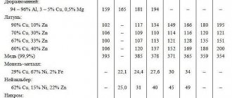
Nickel alloys
Nickel-based non-ferrous alloys are characterized by high toughness and ductility. Nickel parts melt at 700–1000°C, the process is accompanied by saturation of the alloys with gases, the weld becomes porous and fragile. Although nickel is resistant to corrosion. When argon arc welding, electrodes with niobium, silicon, and aluminum are selected. The presence of manganese and magnesium in the melt is also desirable. The weldability of the metal increases and a strong connection is formed.
To work with nickel alloys, welding machines that produce a constant operating current are needed. Welding of nickel non-ferrous workpieces is carried out using a current of reverse polarity so that the shielding gas is ionized and the electric arc becomes more stable. With reverse polarity, the workpiece heats up less than the electrode. This is especially true for workpieces of small thickness. By adjusting the current potential, the temperature of the workpiece can be reduced.
Technological factors affecting weldability
Such features of welding as high heating temperature, small volume of the weld pool, the specificity of the atmosphere above the weld pool, as well as the shape and design of the parts being welded, in some cases cause undesirable consequences:
— a sharp difference in the chemical composition, mechanical properties and structure of the weld metal from the chemical composition, structure and properties of the base metal;
— change in the structure and properties of the base metal in the heat-affected zone;
— the occurrence of significant stresses in welded structures, which in some cases contribute to the formation of cracks;
— formation during the welding process of refractory, difficult-to-remove oxides, which impede the process, contaminate the weld metal and reduce its quality;
— formation of porosity and gas pockets in the deposited metal, violating the density and strength of the welded joint.
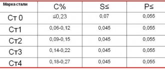
With various welding methods, noticeable oxidation of steel components is observed. In steel, for example, carbon, silicon, and manganese burn out, and iron oxidizes. To determine technological weldability, it is necessary to know the chemical composition, structure and properties of the weld metal, depending on the welding method; evaluate the structure and mechanical properties of the heat-affected zone, the tendency of steels to form cracks, metal oxides obtained during welding and the density of the welded joint.
Existing methods for determining technological weldability can be divided into two groups. The first group includes direct methods, when weldability is established by welding samples of a certain shape. The second group includes indirect methods, when the welding process is replaced by other processes, the interaction of which on the metal imitates the influence of the welding process, for example, heat treatment at temperatures close to the temperatures of the welding process.
The first group of methods gives a direct answer to the question about the preference of a particular welding method and the difficulties that arise when welding with the chosen method, about the rational welding mode, etc.
The second group of methods that simulate welding processes cannot give a direct answer to all questions related to the practical implementation of welding. Indirect methods are considered only as preliminary laboratory tests.
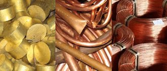
Aluminum alloys
Duralumin, silumin, avmel and other aluminum-based alloys vary greatly in weldability. Aluminum is welded with an electric arc using consumable and non-consumable electrodes, using equipment that generates direct current. The contacts are connected in reverse polarity. It is recommended to preheat the workpieces:
- thickness up to 8 mm – up to 200°C;
- over 8 mm – up to 400°C.
They weld aluminum at currents up to 200 A with sheet thickness up to 4 mm without preliminary cutting of edges. For workpieces over 4 mm, the edges are ground at an angle and cooked at currents 35-40 times greater than the thickness of the workpiece (up to 160 A). A high-quality gas environment is used so that the cloud does not move from the working area during the formation and hardening of the seam. The distance between the tacks is made taking into account the thickness of the workpiece:
| Workpiece thickness, mm | Interval between tacks, mm |
| 1,5 | up to 30 |
| 3 | up to 50 |
| 5 | 5 — 80 |
| 10 | 10 — 120 |
| 20 | 25 — 200 |
The refractory or carbon electrode that ignites the electric arc is held at right angles to the additive to prevent lack of penetration of the weld root.
Weldability test
To determine the tendency of steel to form cracks and changes in the properties of steel in the heat-affected zone, a number of methods are used. Below are the most widely used methods.
Method MVTU im. I. E. Bauman
The roller test determines the following properties of steel, which are manifested under the influence of thermal effects during arc welding: tendency to hardening and overheating, plasticity of steel after heating with an arc, ability to improve the microstructure and increase ductility after welding.
To test a given steel grade, steel from one heat is selected, which is controlled by chemical analysis. If there are several heats of steel of the same grade, tests are carried out on steel containing more carbon.
At least nine plates with a thickness of 12-18 mm are cut from the steel being tested along the rolled product,
Figure 1.
In a closed room at a positive ambient temperature, one bead is fused onto each plate along its entire length, manually or automatically (open arc or submerged arc). Surfacing is carried out manually without transverse vibrations of the electrode. The mode is characterized by heat input
Surfacing modes are given in Table 1.
After cooling, the ends of the plates are ground and etched with a 3% nitric acid solution to determine the penetration limit.
The samples are then marked and cut to prevent tempering or recrystallization of the metal. It is unacceptable to use gas or arc cutting. The number of samples and types of tests are given in Table 2.
During microstudy, the type of microstructure at the fusion boundary and in the zone of maximum hardness at a distance of 0.5-1.0 mm from the fusion boundary, as well as the initial microstructure of the metal, are established. In the zone of maximum overheating, the average size of austenite grains is measured. Grain boundaries are taken according to the ferrite network or the orientation of martensite grains. Grain sizes are measured in cases where their boundaries can be established. The average austenite grain size (in mm) is calculated using the formula
Hardness is measured along the penetration boundary at a distance of 0.5-1.0 mm from it, as well as along the thickness of the metal. Measurements are made at points located at a distance of 2-2.5 mm from one another.
Then the samples, Figure 2,
tested for static bending and impact strength (according to GOST 9454-78, unless there is a later release). The test results are presented in the form of graphs, Fig. 3.
These graphs make it possible to select welding modes that provide specified properties.
Research Institute method
To test sheet steel up to 15 mm thick, six blanks measuring 300 x 45 mm are cut from the edge of the sheets along the rolled steel. The workpieces are placed one by one in a butt welding machine at a distance between the clamps of 65 mm and a current of such strength is turned on that the middle part of the workpieces over a length of 50 mm is heated to 1320-1360ᴼC for 30 s (no more). After cooling in air, a tensile test sample is made from one workpiece, Fig. 4., and a bend test sample is made from the other.
After normalization according to the regimes adopted for steel of a given grade, similar samples are made from the remaining blanks (two for tensile testing and two for bending testing) and tested. By comparing the results of tensile and bending tests, the nature of the change in the properties of steel in the heat-affected areas (during arc welding) is approximately determined.
To test steel with a thickness of more than 15 mm, six blanks with a diameter of 15 ± 0.1 mm and a length of 150-1 mm are turned. The workpieces are heated to 1320-1360ᴼC in a butt welding machine with a distance between clamps of 100 mm for 10 s (no more).
From the middle part of air-cooled (with a distance between the samples of at least 80 mm) samples, samples are made and tested as indicated above. Based on the test results using the research institute's methodology, steel is divided into three classes. HS steel has good weldability; SS-medium weldability; PS - poor weldability.
Class XC includes steels that, after heating and cooling, slightly deteriorate plastic properties (elongation, bending angle and impact strength), but they do not go beyond the lower limits of the standards provided for by technical specifications or GOSTs.
Class SS includes steels whose plastic properties exceed the lower limits of the norms, but are restored after heat treatment to the limits of the minimum requirements of technical specifications or GOSTs.
ClassPS is similar to class SS, but includes steels whose mechanical properties are not restored by heat treatment to the minimum requirements of technical specifications or GOSTs.
The disadvantage of the research institute's methodology is that during testing only the thermal conditions of welding are simulated, all other conditions of the welding process are not taken into account. The research institute's methodology can be recommended as a preliminary one.
Sample from the Institute of Electric Welding named after. E. O. Patosha
A sample for testing metal for technological weldability is a plate measuring 200x400 mm, Fig. 5.
Having four holes with a triangular cut 2.5 mm deep (for the entire thickness of the plate). The plate is welded to channel No. 20 with two transverse seams. A longitudinal bead is welded on automatically. The finished sample is frozen with carbon dioxide, after which it is subjected to impact under a five-kilogram piledriver. The formation of cracks depends on the relationship between the stresses occurring in the area between each pair of holes and the brittle strength of the metal. It is known that transverse stresses during welding are significantly less than longitudinal ones, and longitudinal stresses that cause transverse cracks are greatest near the axis of the weld and decrease with distance from the axis.
To assess the resistance of steel at low temperatures, two criteria can be adopted that influence the occurrence of cracks in the sample:
1) the distance between the axis of the seam and the apex of the notch angle; in this case, the distance changes, and the temperature at which the test is performed remains constant. The best steel is considered to be the one in which cracks appear at a minimum distance between the axis of the weld and the apex of the cut angle;
2) sample temperature at which a crack occurs; in this case, the distance between the weld axis and the apex of the notch angle remains unchanged at all temperatures. The best steel is considered to be the one in which a crack appears at the lowest temperature. It is more expedient to apply the second criterion.
Titanium processing
Titanium in the molten state reacts violently with three components of air: oxygen, hydrogen, nitrogen. It is necessary to reduce their content in the protective atmosphere to a minimum. The gas must be of high quality if you need a reliable seam. It must cool in a protective atmosphere to prevent cracks from forming. For welding titanium on an industrial scale, sealed chambers are used. When manual welding, it is necessary to shield the working area so that the cloud of inert gas does not move from the seam; argon or helium, mixtures must be of the first or highest grade. Due to its high density, the shielding gas will displace air. Welding equipment that generates direct current is used. Welding of non-ferrous metal is carried out with a current of straight polarity. The main thermal load is concentrated on the surface of the workpiece, the root of the weld deepens, the arc is maintained stably, and the metal spatters less.
Research on changes in the structure and mechanical properties of metals during welding using an IMET-4 machine
Existing methods for assessing weldability, based on determining the degree of change in the properties of the metal in the heat-affected zone, make it possible to evaluate the final result of the thermal effect of welding on the structure and properties of the base metal.
At the Institute of Metallurgy named after. A.N. Baykov developed a method for studying changes in the structure and mechanical properties of the base metal under the conditions of the thermal cycle of welding and created an installation for this purpose. According to the research methodology, thin rod samples cut from the metal under study are heated by current, cooled in accordance with a given thermal welding cycle, and at various points in the cycle are subjected to rapid rupture. The heating of the sample is regulated by changing the current intensity according to a given program, and the cooling rate is controlled by spraying with water, blowing with gas, or passing a small current through it.
Changes in the structure and mechanical properties of the metal under thermal cycle conditions are studied separately.
When studying the kinetics of phase transformations, as well as grain growth, a sample measuring 3x5x100 mm is clamped in the heater jaws and subjected to heating according to a given cycle, Fig. 6.
At certain moments of the cycle (for example t1. T2, etc.) the heater jaws automatically unclench, the sample falls into a tank of water and quickly cools. After grinding and subsequent special etching, the sample is subjected to metallographic analysis. In this case, the phase composition is assessed and the grain size is determined. The temperature change in the central section of the sample during heating and cooling is recorded by a thermocouple and recorded on an oscilloscope tape; final changes in the structure and hardness of the metal are studied using conventional methods after heating and completely cooling the sample according to a given thermal cycle.
To study changes in mechanical properties, a sample measuring 3x5x100 mm with a double-sided groove with a radius of 5 mm, Fig. 7, is inserted into the grips of a tensile testing machine.
The sample is heated according to a given cycle (Fig. 6) and at certain points in time (t1. T2, etc.) is subjected to rupture with a curve of changes in force and elongation of the sample over time recorded on an oscilloscope tape. Combined processing of these curves makes it possible to construct a diagram of gain - absolute elongation of the sample P- (Δl).
This technique makes it possible to determine the strength and yield limits and the relative contraction and elongation of the sample metal under rapid tension. The strength limits Gg and yield limits Gt are determined directly from the P-(Δl) diagram, and the relative narrowing ѱ is calculated from the measurement data of the neck dimensions and the average cross-section of the sample recess before and after destruction.
A study of changes in Gg and ѱ of samples under thermal cycle conditions showed that most steel grades are characterized by sequential partial decomposition of austenite in the temperature ranges of pearlite-ferrite and acicular trostite transformation, as a result of the influence of tensile stresses, which sharply increase with destruction in the heat-affected zone. To select rational welding modes and reduce the risk of decomposition, it is necessary to know the nature, as well as the relative change in ѱ and Gg in the specified temperature ranges, depending on the parameters of the thermal cycle (Tmax. t'.t" and the cooling rate of the metal in the heat-affected zone).
These data make it possible to assess the tendency of the metal to harden and overheat and to select optimal welding modes based on the conditions for the most favorable changes in Gg and ѱ during cooling.
A method for assessing the weldability of metals by changes in the mechanical properties and structure of the heat-affected zone under the conditions of the thermal cycle of welding, proposed by the Institute of Metallurgy named after. A. N. Baikov, makes it possible to study not only the final changes in the structure and mechanical properties of the heat-affected zone during welding, but also the kinetics of the process of grain growth and structural transformations. It can be recommended for assessing the weldability of both existing and new metal grades at the early stages of their development.
Works with magnesium
For magnesium parts, the entire edge is boiled. To work with workpieces thicker than 10 mm, you need powerful welding equipment operating from a three-phase network with a power of 380 V, generating alternating high-frequency current. During periods of reverse polarity, the arc breaks through the oxide film and it melts. When working, it is recommended to use pads with low thermal conductivity.
Welding of magnesium and non-ferrous metals based on it is carried out under the atmospheric protection of helium or argon; it protects the melt from saturation with nitrogen, the weld does not bubble, and scale does not form on it. The supply of gas to the working area begins before the arc is ignited, and is stopped 20 seconds after extinction, when the upper part of the seam has set.