Types of surgery
Today, a large number of wire drawing methods are used. If we talk about the types of operation, then it can be of two types. The first type is called dry. In this case, the drawing process is carried out through a container containing soap powder.
The wet type of operation is performed using a soap emulsion. This operation has a processing purity that can also be performed in two categories. The first is the draft, or preparatory. The second type is finishing. This is the final stage that is necessary to create the desired shape and size of the wire.
Drawing also has such a stage as multiplicity. A single or multiple transition is possible. In the second case, it is assumed that the same workpiece will pass through the machine several times. In addition, work can be performed in parallel. That is, the workpiece can be single-threaded, or it can be multi-threaded.
The drags can also differ in their mobility. They can be either a rotating type or a stationary type. The last element that influences the operation is the heating of the workpiece. Naturally, it can be cold or hot.
Basics of the Wire Drawing Process
Wire drawing is a metal forming process characterized by gradual single or multiple drawing of the latter through a special drawing tool designed to gradually reduce the cross-section of the original workpiece.
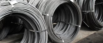
A schematic diagram of drawing is shown in the figure, where 1 – drawing; 2 – wire; Fo is the cross-sectional area at the entrance to the die; Fk is the cross-sectional area at the exit from the die. Wire drawing is much more economical than other methods because When drawing there is no loss of metal into chips, it is possible to obtain wire of a certain diameter with specified properties. Rolling production products are used as a workpiece for drawing - wire rod, obtained by rolling cast billets of a certain section. The most common wire rod size used for further drawing processing is 5.5-6.5 mm. During drawing, a significant part of the energy (according to some data, up to 90%) expended in the drawing process as a result of external friction and plastic deformation is converted into heat, which significantly heats the deformed metal, the die and the lubricant. Excessive heating of the drawn metal (>150-200°C) worsens drawing conditions due to lubricant burnout, and in steel wire it can cause strain aging of the metal. Also, high temperature has a negative impact on the durability of the drawing tool, which heats up significantly higher than the wire. Working conditions and associated requirements for wire products are very diverse. In a rope, for example, the wire should not collapse under the influence of alternating loads and wear out; in the spring it must be elastic enough so that the spring can withstand the applied loads without changing dimensions; The heating element requires stable operation of the wire at high temperatures. Very often, wire is required to have high corrosion resistance, good electrical conductivity and the ability to withstand complex loads. In some cases, the wire must have a whole range of different properties. The quality of the finished wire is determined by the properties of the metal chosen for drawing, as well as changes in its properties during processing. The drawing process is accompanied not only by changes in the geometric shape and dimensions of the workpiece, but also by significant changes in the physical and mechanical properties and structure of the metal being processed. The hardening of the metal that occurs as a result of plastic deformation during drawing is called cold hardening, and the structure of the drawn metal in the form of grains elongated in the direction of drawing is called texture. The degree of influence of deformation during drawing on the physical and mechanical properties of the drawn metal largely depends on the properties of the metal, the magnitude of this deformation and other reasons, but general trends of this phenomenon can be identified: strength characteristics increase (tensile strength, yield strength, hardness); plastic properties (relative narrowing, relative elongation, number of bends and twists) decrease (unevenly); the metal density increases slightly (0.5-1.0%); anti-corrosion resistance is slightly reduced; electrical resistance increases (for austenitic steel the increase is up to 30%); the magnetic properties of the metal change. During plastic deformation during drawing, the structure of the metal undergoes significant changes - pearlite grains are elongated in the direction of drawing, the number of structural defects (dislocations, vacancies, interstitial atoms) increases, which leads to an increase in strength, hardness and a decrease in ductility. These phenomena are called drawing hardening. Further deformation leads to the formation of microcracks, which grow and, when a certain degree of compression is exceeded, lead to wire breaks. To be able to continue drawing, it is necessary to remove the hardening of the wire using heat treatment methods. To do this, tempering, normalization, annealing or patenting are used, depending on the conditions and grade of steel. During heat treatment, the number of structural defects decreases; with further heating, small equiaxed grains with an undeformed metal structure are formed from deformed (elongated) grains, which grow and gradually occupy the entire volume of the material. This phenomenon is called recrystallization. At the same time, strength and hardness decrease, ductility increases. However, for carbon steels, especially at high degrees of reduction during drawing, recrystallization is not enough for normal drawing in the future. The steel is heated above the austenitic transformation temperature to achieve refinement of the pearlite structure and healing of microcracks. On flow units, the heating of the wire should be 900 - 960 ° C, so that these changes in the structure can occur in a short time of exposure in the furnace. Classification of drawing according to thermal conditions of deformation Hot drawing - drawing under conditions of post-recrystallization temperatures (up to 900 ° C) is used for those metals and alloys that cannot be drawn at normal temperatures due to low ductility: tungsten, molybdenum, some titanium and aluminum alloys. Heating of the wire directly in the process flow with drawing is carried out, as a rule, by electric contact or induction methods. Thermal drawing - drawing at temperatures of up to - or near-recrystallized order up to 500 ° C (high-speed steel). Low-temperature drawing - drawing in the temperature range from - 60 ° C to - 180 ° C is of interest for the production of wire from high-alloy steels with an austenitic and austenitic-ferritic structure, as it helps to increase the stability of austenite, increase ductility and improve the mechanical properties of the drawn metal. Methods of drawing with a reduced coefficient of friction Drawing with counter tension. Counter tension Pq is a force applied to the metal entering the die and directed in the direction opposite to the direction of drawing. With an optimal ratio of the values of drawing stress and counter-tension stress, depending on specific drawing conditions, the specific pressure of the metal in the deformation zone is reduced and, as a consequence, the coefficient of external friction and wear of the drawing channel are reduced. Vibration drawing – drawing with the application of vibrations to the wire or die, and in some cases to the wire and die at the same time. At an optimal vibration frequency of the order of 200-500 Hz, the drawing force can be reduced by 35-45% due to a decrease in the coefficient of external friction in the deformation zone. Drawing through a rotating die reduces the coefficient of friction during drawing, but requires additional power and a special complex drive, which limits the use of this drawing method. Wire drawing through non-driven roller dies significantly reduces the coefficient of external friction in the deformation zone, since with this drawing method the sliding friction between the surface of the drawn wire and the stationary drawing tool is replaced by rolling friction (in the roller die supports) between wire 5 and roller dies rotating from the moving wire 6. This allows you to increase individual and total reductions when drawing wire from hard-to-deform metals and alloys. This method is also used for drawing periodic and shaped wire, firstly, for the reason stated above, and secondly, due to the lower costs of manufacturing a roller die compared to the costs of manufacturing a similar monolithic shaped die. Products obtained by wire drawing Hardware production is one of the main parts of metallurgical production. Hardware products include: wire, rope products, metal cord, twisted reinforcement for reinforced concrete, metal mesh, welding electrodes, tape, springs, bolts, nails, screws, screws, etc. One of the main types of hardware is wire; the most common cross-sectional shape is a circle. Wire finds the widest application in all industries, agriculture and other spheres of human life and activity. It is used in the form of both finished products (electrical and telegraph wires, wire for reinforcing reinforced concrete structures for industrial and civil purposes, strapping and packaging material, etc.) and semi-finished products for the production of a whole range of hardware: steel ropes, welded and woven mesh, nails , screws, machine parts, wire and cable products, for reinforcing car tires (bead wire), high-pressure hoses, welding operations (welding wire, electrodes). Recently, the direction of reinforcing building materials with wire (fiber), etc., has begun to develop. Wire is manufactured in a wide range from a wide variety of ferrous and non-ferrous metals and alloys, with different mechanical and physical and chemical properties. Each type and size of wire requires a specific manufacturing technology and appropriate equipment.
The essence of drawing
Currently, it is possible to draw aluminum, copper or steel wire. Equipment in which there is a hole of the required diameter is called a die, hence the name of the procedure. The hole itself is called a die. The final result of the entire procedure will depend on its shape.
In addition, if we compare the procedure of wire drawing and rolling, the first method is much more effective, since it will ensure greater cleanliness as well as precision of the wire surface. In addition, this procedure is also characterized by the fact that in the process of its implementation mechanical performance improves, which is due to the removal of hardening. Currently, it is possible to produce wire with a diameter from 1-2 microns to 10, and in some cases more, millimeters.
Selection of dies depending on the purpose
Considering that dies (dies) for wire drawing (or other types thereof) experience enormous dynamic and temperature effects, special attention is paid to the technology of their production. For these purposes, synthetic, diamond structures or hard alloys of special strength are predominantly used. Also quite often used is the so-called tool steel. The choice of product itself directly depends on the characteristics of the production process and its planned economic indicators.
For example, pressure dies (dies) are capable of effectively ensuring the flow of a lubricating, servicing agent directly into the deformation zone. In practice, the friction generated during operation is reduced several times, as well as the deformation force. Thus, the pressure die (die) guarantees a reduction in energy consumption during machine processing. In addition, the wear of the die will be insignificant and will not require its rapid restoration or replacement. As for the main area of its use, it is exclusively “dry drawing”, where special lubricants are used in powder form.
Drawing technology and stages
It is worth noting that with the current development of technology, wire drawing on modern equipment guarantees fairly high productivity. And this is a very important point. Wire drawing equipment can easily operate at a fairly high speed, without any disturbances. The speed that the units can develop reaches 60 m/s.
The process takes place in several main stages:
- The first stage is etching of the sources. For this, a sulfuric acid solution is usually used, which is preheated to a temperature of 50 degrees Celsius. The operation is necessary in order to increase the service life by removing scale.
- The next procedure is annealing. It is necessary in order to increase such characteristics as plasticity, as well as to form fine grain.
- The third stage is the removal of residual sulfuric acid solution. To do this, the substance is washed and neutralized.
- Using a hammer, the ends of the workpiece are sharpened.
- At this stage, direct drawing of steel wire or any other occurs.
- The last stage is the annealing of the finished product again.
Technological process for manufacturing wire from non-ferrous metals and alloys
- GENERAL INFORMATION
The technological process of wire manufacturing is a series of sequential operations (etching, heat treatment, drawing and others), during which the cross-section of the workpiece is reduced and the necessary properties of the wire are achieved.
The quality of the product and the economic indicators of wire production depend on the technical level of the process. An important condition for reducing labor costs in wire production is reducing cycles. This is achieved by drawing the wire with the maximum possible total reductions (Table 1).
Table 1
Allowable total compression
| Alloy or metal | Maximum total compression, % | Alloy or metal | Maximum total compression, % |
| Copper M1 | 99,9 | Constantan | 99 |
| L80 | 95—99 | Nickel | 99 |
| L62 | 80—96 | Alumel | 80-90 |
| LS 59-1 | 40—50 | Chromel | 80—90 |
| BrB-2 | 35-85 | Monel metal | 80-95 |
| BrKMtsZ-1 | 80—90 | Aluminum | 99,9 |
| BrOTs4-3 | 80—99 | Zinc | 99,9 |
| Manganin | 99 | Titan (VT1) | 45-60 |
They depend mainly on the ductility of the metal and the diameter of the wire being processed. The smaller the diameter, the greater the permissible total compression. For example, when drawing beryllium bronze wire from a 7.2 mm wire rod at the beginning of the process to a size of 4.5 mm, reductions between anneals equal to 30–40% are allowed, and from a workpiece with a diameter of 1.0–0.5 mm, drawing is carried out with a total reduction 75-85%.
An important factor determining the wire production technology is the workpiece and the method of its production. The labor intensity of production and the quality of the wire depend on the diameter of the workpiece and its quality.
2. WIRE BLANK
The blank for making wire is obtained in the following ways:
1. Rolling ingots on a wire rolling mill to a diameter of 6.5-19 mm. This method is the most productive and is widely used to obtain workpieces from copper, copper alloys, aluminum, nickel, nickel and copper-nickel alloys, brass (L62, L68, LA85-0.5), zinc, bronze (OTs4-3, KMC -3-1, BB2), titanium and titanium alloys.
2. Hot pressing on hydraulic presses. This method can produce workpieces with a diameter of 5.5-20 mm and higher with a high surface quality. However, this method is less productive than rolling and is associated with the production of significant geometric waste - from 10 to 25%. At the same time, during rolling this waste amounts to 2-4%. By pressing, a billet is obtained from alloys whose section rolling is difficult, for example, brass LS59-1, LS63-3, etc., as well as when it is necessary to obtain wire with a high surface quality and a complex profile.
3. By cutting cold-rolled discs in a spiral with special scissors into a rectangular workpiece (for example, 6x8 mm in size). This method is used for alloys that cannot withstand hot deformation. Phosphor bronze is one of these alloys.
4. By metal-ceramic method - by sintering powders into long rectangular blanks and then forging them on rotary forging machines. This method is used for refractory metals (molybdenum, tungsten, etc.).
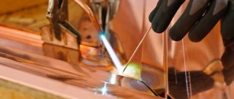
3. MANUFACTURING WIRE FROM COPPER
The blank for drawing copper wire is a wire rod with a diameter of 7.2-19 mm or a rectangular cross-section. To produce complex wire, a pressed blank of the appropriate profile is used. The workpiece is etched in an 8-12% aqueous solution of sulfuric acid, heated to 40-50 °C. Drawing of wire rod with a diameter of 7.2 mm, pre-butt welded, is carried out on sliding machines of the VM-13 type to a size of 1.79-1.5 mm. A soap-oil emulsion is used for lubrication and cooling. Further drawing is carried out on a 22-fold machine to a size of 0.38-0.2 mm, drawing speed up to 18 m/sec. Then drawing on 18-fold machines to diameters of 0.15-0.05 mm. At the last stage of drawing, diamond dies are used. The angle of the working cone of the die is 16-18°.
Wire with a diameter of 0.15-0.05 mm is produced without intermediate annealing. If necessary, non-oxidizing annealing is carried out, as a rule, on finished sizes in conveyor electric furnaces with a water seal or in shaft electric furnaces without air access.
Some cable industry plants operate drawing machines with combined annealing of copper wire. The use of such machines makes it possible to reduce the labor intensity of wire production and increase the degree of automation of production. Currently, they are working to improve the quality of wire annealing on these machines.
4. MANUFACTURING WIRE FROM ALUMINUM
Aluminum wire is made from rolled billets with a diameter of 7-19 mm. During hot rolling, aluminum is coated with a very thin layer of oxides, the effect of which on the drawing process is insignificant, so the hot-rolled billet is usually not pickled. But during long-term storage, a layer of oxides forms on the metal, which is recommended to be etched off. In this case, etching is carried out in an aqueous solution containing 8-12% H2SO4.
The production of medium and thin aluminum wire is carried out according to the following scheme.
Drawing of wire rod with a diameter of 7.2 mm by 1.8 mm is carried out on multiple machines without sliding, type VMA-10/450. Next, drawing to a size of 0.47–0.59 mm is carried out on 15 sliding drawing machines; drawing speed up to 18 m/sec.
On machines without sliding, a thick lubricant is used, on machines with sliding, a soap-oil emulsion is used.
When drawing aluminum wire repeatedly, in order to reduce breakage, the drawing value is taken to be 5% lower than for copper. Dies are used with a working cone angle of 24-26°.
5. MANUFACTURING WIRE FROM ZINC
Zinc wire is made from zinc grades TsO and Ts1. The workpiece for drawing is a wire rod with a diameter of 7.2 mm, it is drawn to a size of 3.7 mm on a 6-fold machine with a 6/480 type sliding. The lubricant is a soap-oil emulsion prepared from Ts4 paste with the addition of sulfur. Next, drawing on machines with sliding type 8/250, 10/250 from a diameter of 3.7 mm to finished sizes of 1.5-2 mm. The lubrication is the same as for the previous drawing stage. When drawing zinc wire, special attention should be paid to the preparation of the lubricant and the dies. To reduce the effort to overcome friction, it is recommended to reduce the contact area of the wire in the deformation zone, for which the angle of the working cone of the die is increased to 24-26°, and the length of the working belt is reduced to 0.3 of the diameter of the finished wire.
Zinc wire rod is usually not pickled, since the thin layer of oxides covering it does not affect the drawing process.
6. MANUFACTURING WIRE FROM TITANIUM
The blank for drawing titanium wire is a wire rod with a diameter of 8 mm. Drawing is carried out on single or multiple machines without sliding into carbide metal-ceramic dies. Dry powdered graphite is used for lubrication. Drawing speed from 20 to 50 m/min. The permissible total compression when drawing wire from titanium grade VT1 is from 45 to 60%. After such deformation, annealing is carried out in electric furnaces at a temperature of 620-640°C, holding at this temperature for 20 minutes.
Annealed coils of wire are immersed in a salt-lime solution of the following composition: 100-150 g/l slaked lime (CaO) and 80-100 g/l table salt (NaCl). The solution temperature is 80-90 °C. After treatment in the solution, the coils are dried in a stream of warm air. The lime layer obtained on the surface of the wire promotes better capture of dry powdered graphite.
The finished wire is etched to remove the alpha layer. After etching, the wire is vacuum annealed to increase ductility and reduce hydrogen content. Annealing temperature 750–800 °C, holding time 4–6 hours, cooling in an oven to 250 °C. The furnace maintains a vacuum from 13.3 to 6.65 mN/m2 (from 1 10-4 to 5 10-5 mm Hg).
Using this technology, titanium wire of grade BT1 with a diameter of 1.2 to 7 mm is produced. Drawing is carried out in carbide metal-ceramic dies with a working cone angle of 8-10°.
Wire from titanium alloys is made using the same technology, but with a large number of intermediate anneals, since the permissible total reduction when processing alloys is reduced to 30-40%.
7. PRODUCTION OF WIRE FROM NICKEL AND ITS ALLOYS
Wire made of nickel and its alloys is made from rolled billets. The surface of wire rods made of nickel alloys and the workpiece after annealing have a very dense oxide film that interferes with the drawing process, therefore, in the production of wire, special attention is paid to surface preparation. For this purpose, combined alkaline-acid and acid-salt etching, lime-salt coating of the workpiece surface is used.
Drawing wire from nickel and copper-nickel alloys, which have high hardness and strength, is associated with increased wear of the dies, therefore, in the production process of this wire, much attention is also paid to the issue of die durability. For this purpose, the quality of metal surface preparation, die preparation and lubrication is improved, and wire drawing under fluid friction conditions is being introduced. Currently, wire drawing from nickel, silicon nickel, manganese nickel, constantan, chromel on multiple machines without sliding is carried out in the so-called prefabricated dies, creating conditions of liquid friction.
Wire made of nickel and its alloys is annealed in shaft-type electric furnaces without air access, as well as in broaching electric furnaces. To obtain a bright surface, it is recommended to anneal in a generator gas environment, dissociated and incompletely burned ammonia containing 5% hydrogen, or in pure dried hydrogen. Annealing of thermoelectrode wire at finished sizes is carried out in an oxidizing environment to obtain a reliable oxide film, which largely determines the properties of the wire (stability, etc.).
8. MANUFACTURING WIRE FROM TUNGSTEN
The blank for tungsten wire is tungsten rods with a square section of 15X 15 mm, about 0.5 m long, produced by the metal-ceramic method.
Before drawing, the rods are forged on rotary forging machines to a diameter of 2.5-3.0 mm. The forged workpiece is drawn to a diameter of 1 mm on chain drawing mills up to 30 m long. The drawing is hot, for which the mill is equipped with a gas furnace. Before the task of drawing, the end of the rod is sharpened by heating to a cherry-red color and immersing it in a box of dry potassium or sodium nitrate. Under the influence of high temperature, the salt dissolves and uniformly dissolves the ends of the tungsten rods over a length of 100-120 mm. Avoid getting potassium or sodium nitrate into the die channel to avoid damage. After sharpening, the remaining potassium or sodium nitrate is washed off from the end of the rod with water and lubricated with a colloidal graphite preparation of grade B-1. The pointed end is heated in an oven and pulled into the die to a length of up to 200 mm. Then the end of the rod is heated together with the die, quickly installed in the die holder and pulled.
Drawing is carried out at a speed of 0.1-0.15 m/sec. Carbide dies with a working cone angle of 8-10 degrees. Before drawing, the die is heated to a temperature of 500 °C, and the wire to 1000-850 °C, depending on the diameter (as the diameter decreases, the temperature decreases).
In this way, the process is repeated 7-8 times until the diameter is 1 mm, after which the wire is rolled into a skein.
Further drawing to a size of 0.5-0.55 is carried out on single drawing machines with 6 broaches. From the figure, the wire passes through a lubricant box with a colloidal graphite preparation of grade B-1, diluted with distilled water in a ratio of 1:1, enters a gas furnace, where it is heated to a temperature of 800-750 ° C, and is pulled into a pobedit die at a speed of 0.16 -0.20 m/sec and is taken on a drum with a diameter of 500 mm.
Drawing to thinner sizes is carried out according to the same scheme with the wire being received on drums with a diameter of 200 mm or on coils. Drawing speed up to 0.3-0.4 m/sec. For lubrication, a preparation of grade B-1 is used, diluted with distilled water in a ratio of 1: 2. Wire drawing with a diameter of 0.34-0.32 mm and below is carried out in T-type diamond dies, which are heated before drawing to 400 ° C.
9. MANUFACTURING WIRE FROM PRECIOUS AND RARE METALS
To make silver wire, a rolled or pressed piece with a diameter of 7-8 mm is used. The workpiece is drawn without intermediate annealing to a size of 0.26 mm according to the following scheme. Single drawing is used up to a diameter of 3-3.5 mm. Laundry soap is used as a lubricant. Drawing at this stage can be carried out on multiple sliding drawing machines of the VM-13 or SMV-P-9 type. Drawing to a size of 1.2 mm is carried out on a 15-fold sliding machine of type 15/250, then on a machine of type 22/200 to a diameter of 0.26 mm. At this size, annealing is carried out in a chamber electric furnace at a temperature of 250 ° C, holding for 30 minutes.
Further drawing to the finest dimensions up to 0.02 mm is carried out on 18 sliding drawing machines without intermediate annealing. On sliding machines, soap emulsion is used as a lubricant. Carbide metal-ceramic dies with a working cone angle of 16-18 degrees. For the finest drawing, type M diamond dies are used.
During the processing of silver wire, the workpiece and intermediate dimensions are not etched after annealing. Particular attention is paid to the cleanliness of the workplace, the quality of the wire surface, and preparation of production in order to eliminate breaks and metal losses.
To obtain wire of the thinnest diameters (up to 0.001 mm) from gold, platinum and alloys of precious metals, drawing in a copper jacket is used, for which a rod of precious metals or alloys with a diameter of up to 2 mm is placed in a copper tube with a diameter of 10 mm and a wall thickness of 4 mm . Such a bimetallic workpiece is drawn to the design size.
So, to obtain platinum wire with a diameter of 0.01 mm, drawing a bimetallic workpiece is carried out to a diameter of 0.05 mm, to obtain a diameter of 0.005 mm - drawing to 0.025 mm, for a diameter of 0.004 mm - drawing to 0.02 mm, etc. Before Using a wire made of noble metals, the top layer of metal (copper jacket) is removed from it with a solution of nitric acid in distilled water in a ratio of 1:1.
Wire from beryllium and its alloys with a diameter of 1 to 0.12 mm is produced by drawing at temperatures of 420–450 °C. Compression per pass is 25%. Colloidal graphite in oil is used as a lubricant, as well as a mixture of graphite and molybdenum disulfide. After every third pass, the wire is subjected to intermediate annealing at 800 °C for 6 hours 30 minutes. The surface of the wire is cleaned using the ultrasonic method, since etching reduces its mechanical properties.
10. MANUFACTURING WIRE FROM BRASS
The ductility of brass is lower than the ductility of copper, so during processing they are cold-worked faster and intermediate annealing is required. According to the ductility of brass, it can be divided into three groups: 1) ductile brasses containing more than 78-80% copper. These include brass L80, LA85-0.5, L90, etc.; 2) brass of medium ductility, containing 60-70% copper. These include L62, L68; 3) brass of low ductility. These include brass grades LS59-1, LO60-1.
The production of thick and medium-sized wire from brass of the first group can be carried out without intermediate annealing; thin sizes - with one intermediate annealing and the finest - with two annealings.
From brasses of the second group, thick wire is produced without intermediate annealing; medium-sized - with one and two intermediate anneals; thin sizes - with three anneals and the finest - with four intermediate anneals.
Wire from brass of the third group with a diameter above 5 mm is produced from a pressed billet of the appropriate diameter without intermediate annealing. Wire with a diameter below 5 mm is produced with intermediate annealing every 30-40% reduction.
With improved technology for preparing the metal surface before drawing, improving the quality of the drawing tool and lubricant, as well as improving the quality of the workpiece, the total reductions when drawing brass wire can be increased and, consequently, the number of intermediate anneals can be reduced.
Due to the large gradation of brass wire in terms of mechanical properties, heat treatment in the technological process of a number of brands of brass wire (L62, L68, etc.) is important, determining the quality of the wire (mechanical properties) and the conditions for its further processing. In the production process of brass wire, special attention should be paid to annealing, in terms of its uniformity, and preparing the surface of the wire after annealing for further processing. Repeated drawing of brass wire of medium and thin diameters is carried out with partial reductions of 17-18%. It is advisable to work at lower compression rates if the machine allows.
Etching of wire blanks and intermediate sizes after annealing is carried out in a 5-15% aqueous solution of sulfuric acid. Satisfactory quality of etching of brass wire is obtained if it is immersed in a solution on a device that ensures uniform etching of each coil.
To obtain a light-colored surface of the wire after annealing, in some cases, etching is carried out in a solution containing 2 parts of sulfuric acid, 1 part of nitric acid and 6 parts of water, followed by passivation in an aqueous solution containing 150 g/l of chromium and 400-450 g /l sulfuric acid. After passivation, neutralization is carried out in an alkaline solution. Brass wire is annealed in shaft electric furnaces without air access and in broaching electric furnaces.
The most uniform annealing is obtained in broaching electric furnaces, as well as in shaft electric furnaces with forced air circulation. Good results in uniform annealing of L62 wire were obtained in well-type electric shaft furnaces equipped with automatic temperature control by zone, taking into account the thermal inertia of the furnace. At the same time, narrow limits of the mechanical properties of the wire were achieved in one batch: tensile strength from 400 to 460 MN/m2 (40-46 kgf/mm2), and in one coil the fluctuations did not exceed 30 MN/m2 (3 kgf/mm2) (the wire was made of brass grade L62 with a copper content of 62-63%).
For drawing brass wire, carbide cermet dies with a working cone angle of 14-18 degrees are used. Wire with a diameter below 0.2 mm is pulled into type P diamond dies.
Feature of the operation
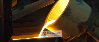
Naturally, any operation has its drawbacks. According to experts, drawing has only one, but rather serious, disadvantage. It consists in the fact that the wire is subject to slight deformation during the operation. Most often, the starting raw material for wire drawing is a continuously cast, pressed, rolled billet made of non-ferrous metals, ferrous metals or carbon, alloy steels. In other words, in order to achieve high quality wire, it is necessary to use fairly high-quality raw materials.
Previously, for the production of wire by drawing, steel blanks were used, which, after undergoing the procedure, were processed in such a way as patenting. This is a heating process, at a certain temperature of which a process such as austenitization and exposure in salt or lead melts took place. This product was aged at approximately 500 degrees Celsius.
Types of modern units
Currently, metal processing plants use two types of equipment. They differ from each other in the type of pulling mechanism.
- In the first case, the wire drawing technology consists in the fact that the product is wound on a drum, thereby creating a traction force.
- The second case is the use of a device that pulls the workpiece in a straight line.
If we talk about application, the second type of units is most often used when it is necessary to stretch a pipe blank that does not require subsequent coiling.
The bulk of wire and small-section pipes are produced on drum devices. These mechanisms can be either one-time or multiple-time. Naturally, the simplest design is for single-use equipment. The production process in this case involves drawing the wire in one pass. If a multiple machine is used, the procedure can be repeated two or three times in a row.
Construction of working machines
The main working element is a device that is present in any wire drawing apparatus - a die. This mechanism is always created from a very durable cermet alloy. A distinctive feature of this metal is that it is very durable, has increased hardness, low viscosity, and is also highly resistant to abrasion. In rare cases, industrial diamond is used to produce a die. This provides a significant advantage when processing more complex metals.
These parts are placed in fairly strong and tough steel cages. The cage itself is not capable of exerting a strong influence on the die, but its presence significantly reduces the tensile stress that inevitably arises during operation. Modern enterprises quite often use prefabricated dies, which differ in that they consume less energy and their efficiency is approximately 30% higher.
What should you pay attention to first?
In general, you should not forget that before purchasing dies (dies) for drawing wire or their other modifications, you should make sure of its performance characteristics. The most important thing is to get information about its real durability. This parameter indicates the actual amount of wire that is pulled before mechanical failure of the tool itself. Wear resistance is separately assessed, which means the number of products obtained per 1 unit of internal channel (measured in microns).
Solutions for various technological problems
But scalping dies (dies) make it possible to obtain higher quality and competitive wire due to special mechanical action. As a result, the output wire acquires the properties of improved resistance to corrosion processes, as well as the fight against aggressive impurities affecting the metal surface. Moreover, scalping dies (dies) can be used for material with a diameter of 16 mm (including brass, copper and aluminum).
If the purpose of your technological process is the need to draw chromium-nickel steels, then it would be advisable to buy carbide dies (dies). The fact is that this particular type of product stands out for its ideal balance of operating performance and overall efficiency. It would not be superfluous to mention their high resistance to friction under conditions of daily, non-stop use. And the good suitability for grinding of carbide dies (dies) is beyond doubt.
Preparing metal for work
Naturally, such a procedure cannot be carried out without preliminary preparation of the metal. In addition, without this procedure it will not be possible to achieve a high-quality product. The essence of the preparatory work is that it is necessary to remove scale from the workpiece. Before starting the wire drawing process, one of three procedures is carried out:
- mechanical restoration;
- chemical treatment;
- electrochemical processing.
Mechanical cleaning of the workpiece is the simplest and cheapest cleaning method. It is most often used if the product is made of carbon steel. During the processing procedure, the wire rod is bent in different directions. At this time, its surface is treated with mechanical brushes.
Chemical and electrochemical processing
As for the chemical method of descaling, it is more complex and also labor-intensive. For this, either hydrochloric or sulfuric acid is most often used. In addition, to perform such an operation, the drawer must have the necessary qualifications to work with chemicals.
However, it is important to note here that this method is indispensable if it is necessary to prepare high-alloy or stainless steel for drawing. In addition, after chemical cleaning is completed, the metal surface must be rinsed with water.
The last method, electrochemical, involves etching the metal in an electrolytic solution. This liquid can be either anodic or cathodic, depending on the conditions, as well as taking into account the characteristics of the material.
Drawing of copper blanks
When drawing copper wire from copper blanks, cast blanks are always used, and this is what the entire method is based on. First you need to fuse all the workpieces together. Immediately after this, while they are still hot, they are rolled. However, this process entails the appearance of a film of oxides on the surface of the product. To get rid of this problem, it is necessary to carry out treatment with chemical compounds. After this, you can proceed directly to the drawing procedure.
The production of copper wire can also be carried out using the principle of submersion molding. If you use this method, the surface of the wire rod will remain clean and the cleaning procedure will be avoided. This is the method used to produce the thinnest wires (up to 10 microns in diameter). However, when using this method, it is very important to choose a composition that will have suitable properties.
Among these compositions are:
- complex solutions, which can be alkaline compounds, salts of fatty sulfonated oils and several other substances;
- it is possible to use various types of emulsions, such as anionic, anti-foam, synthetic ethers and others;
- Synthetic substances, such as organic and inorganic salts, as well as polymer solutions, are considered separately.
Coolant for drawing copper wire
by product Coolant for copper wire drawing
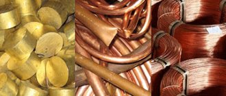
The most common metal used for wire drawing is copper, due to the widespread use of this wire in the electrical and electronics industry.
The maximum thickness of copper wire is 20 mm, the minimum is 10 microns. The production of copper wire occurs with various reductions in cross-section: coarse drawing (coarse wire) - 25%, ultra-fine wire (ultra-fine drawing) - 9%, respectively, thinning occurs by 33% for coarse drawing and 10% for ultra-fine drawing.
Processing options
Currently, there are a large number of different options for processing workpieces.
- Cove type of processing. This is an option for working with pipes from blanks that are assembled into coils. This also includes those pipes that have undergone a drawing process, after which they were assembled into coils.
- The wet type of processing assumes that the die will be immersed in liquid lubricant during operation.
- The most commonly used application is the die on fixed mandrels.
- There is a processing method that allows the use of pipes that do not have a round (shaped) shape.
- The electroplastic method is used if there is a need to work with drawing metal that is quite difficult to deform.
- Another processing method is the rod one. A rod is inserted into the workpiece in order to pull it along with the pipe. After passing through the drag, the inserted rod must be removed back.
Diameter difference
The drawing process is divided into several more types, depending on what the initial diameter of the workpiece was and what it turned out to be in the end. Rough drawing is a procedure in which the initial diameter was 8 mm, and after passing the drawing it became from 5 to 0.9 mm. Medium drawing is considered to be an operation in which the workpiece had a diameter of 3.5 mm, and as a result it decreased to 1.5-0.2 mm. In fine drawing, workpieces from 2.6 to 1.6 mm are used. The result is products with a cross-section from 0.5 to 0.05 mm.
Lubricants for copper wire drawing
When drawing copper wire, use only water-based lubricants. At the beginning of wire processing, during rough drawing, high-viscosity oils are used for optimal working process. For wet drawing, emulsions are mainly used.
At the Zeller+Gmelin GmbH & Co. plant KG. A wide and comprehensive range for copper wire drawing and production.
The quality of the copper is the most important factor when choosing a drawing lubricant. Secondary factors are the drawing machine and the dies used on it.
The most common and important wire drawing is medium copper drawing, although all types of wire drawing from coarse to superfine should ideally be done together.
| Type of drawing | Wire diameters, inlet and outlet | |
| Initial diameter, mm. | Final diameter, mm. | |
| Rough drawing | 8.0 | 5.0 – 0.9 |
| Average drawing | 3.5 | 1.5 – 0.2 |
| Fine drawing | 2.6 – 1.6 | 0.5 – 0.05 |
| Ultra-fine drawing | 0.5 | 0.14 – 0.025 |
| Ultra-fine drawing | 0.35 | 0.1 – 0.01 |
Average drawing speed: from 20 m/s to 30 m/s up to 40 wires being drawn simultaneously.
Now let's go directly to the stages of production of copper wire and the products that we can offer you for this.