Melting point of aluminum 660°C, oxide film 2060°C
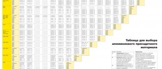
| Brand | Weldability | Technological features of welding | |
| Technically pure aluminum | Edge cleaning and oxide film additive | ||
| AD00, AD0, ADD, AD | good | Electrode wire Sv-A1, Sv-A000, Sv-85T. Shielding gases Ar, He and their mixtures | |
| Deformable, thermally non-hardening alloys | |||
| AMts, AMtsS, D12 | good | Electrode wire Sv-AMTS | |
| AMg1, AMg2, AMg3 | Electrode wire Sv-AMg3 | ||
| AMg4, AMg5 | Electrode wire Sv-AMg5 | ||
| AMgb | Electrode wire Sv-AMg6, Sv-AMg7 | ||
| Deformable, thermally hardenable alloys | |||
| AD31, ADZZ, AD35 AB, AK6, AK8 | Satisfactory | Electrode wire Sv-AK5, Sv-1557 Shielding gases Ar, He and their mixtures | |
| AK4, AK4-1 | Limited | ||
| B95 | Bad | Preheating Heat treatment after welding at t=200-250°C. Electrode wire Sv-1557, Sv-AMg5, Sv-AMg6 | |
| 1915, 1925 | Satisfactory | ||
| Casting alloys | |||
| AL 1, AL2, AL9, AL 25, AL 26 | good | Electrode wire of the same grade as the base metal Shielding gases Ar, He and their mixtures | |
| ALZ, AL4, AL5, AL7, AL8, AL 10V | Satisfactory | ||
Preparation for welding
Cutting and edge preparation of parts made of aluminum and its alloys should be carried out using mechanical methods.
Butt joint of metal of different thicknesses
Structural elements for edge preparation (dimensions in mm)
Structural elements of edge preparation when welding with through penetration and formation of a seam in weight
When welding in one pass, a cut in the root of the seam may occur.
When chamfering from the reverse side of the edges being joined, a cut does not occur. You can use a file to remove chamfers
The surfaces to be welded are thoroughly cleaned of grease, and degreased with acetone, white spirit or other solvent at a width of 100-150 mm from the edges.
The aluminum oxide film is removed mechanically or chemically.
During mechanical processing (immediately before welding), the edges are cleaned to a width of 25-30 mm with abrasive paper, a scraper or a brush made of stainless wire with a diameter of no more than 0.15 mm.
Chemical etching is carried out for 0.5-1 minutes in a solution consisting of 50 g of caustic soda and 45 g of sodium fluoride per 1 liter of water. After etching, the surface is washed with running water and then brightened in a 30-35% solution of nitric acid (for aluminum and AMts type alloys) or in a 25% solution of orthophosphoric acid (for AMg and B95 type alloys). After repeated washing, the surface is dried until the moisture has completely evaporated.
Aluminum welding wire is also treated before welding. First, it is degreased and then etched in a 15% sodium hydroxide solution for 5-10 minutes at 60-70°C. followed by rinsing in cold water and drying at 300°C for 10-30 minutes.
Materials prepared for welding retain their properties for 3-4 days. Later, an oxide film forms on the surface again.
Parts made of aluminum and its alloys are assembled in fixtures or tacks, performed by argon arc welding with a W-electrode. The distance between the tacks should be no more than 150-180 mm.
The surfaces of the tacks are cleaned with metal brushes immediately before welding. Defective tacks found are removed and the joints are re-tacked. When welding, the tacks are completely melted.
Difficulties of the process
Before moving on to a direct description of the process, it is necessary to consider which features of the metal are considered unique, since the main task of the welder is to increase the already low weldability of aluminum.
Aluminum is quite active, especially in chemical reactions with oxygen. As a result of oxidation, an oxide film quickly appears on the surface, even after treatment. It differs in physical properties from the base metal.
The melting point of an aluminum oxide film is 2044°C degrees, while the metal itself melts at 660°C degrees.
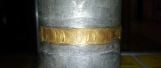
After welding, molten aluminum begins to crystallize, and the droplets, coated on the outside with an oxide film, form a cellular structure. The weld seam is not continuous, and this leads to the formation of fistulas and pores. Seam defects negatively affect its strength and tightness. To prevent the interaction of aluminum with oxygen, the heat-affected zone is protected from atmospheric air. Argon is usually used for such purposes. Due to the pile’s inertness, it does not interact with the metal, and also displaces oxygen, since the inert gas is heavier than air.
Despite its high thermal conductivity, molten aluminum does not have time to transfer heat to the environment. Increased fluidity significantly complicates the process of seam formation. It is necessary to additionally use various heat-dissipating pads. If you use various means that provide intensive cooling, then a sharp temperature difference can cause small cracks to appear.
Another problem is hydrogen dissolved in liquid metal. It rises to the surface of the bath in the form of bubbles, but not all comes out. Pores or clusters of pores may form in frozen metal. The presence of silicon in the alloy promotes the formation of cracks during crystallization.
When heated, the aluminum billet increases in size. thermal expansion is inherent in every metal, but aluminum has a high coefficient of linear expansion. However, the quality of welding is affected not so much by the expansion of the metal as by its shrinkage during crystallization of the pool. The weld seam may be subject to severe deformation.
The high thermal conductivity of aluminum also affects welding parameters. To achieve the desired arc temperature, the current must be increased. Note that welding of ferrous metals is carried out at lower values of welding current, despite the fact that their melting point is higher than that of aluminum.
Finally, the last difficulty that prevents work at home is that without special tools and materials it is almost impossible to determine the composition of the alloy from which the parts are made.
Selecting mode parameters
Welding is carried out using direct current of reverse polarity. The protective gas is argon or helium and their mixtures. Immediately before welding, the edges are degreased.
The diameter of the burner nozzles is chosen to be at least 18-22 mm.
The arc length should be 2-6 mm, and the welding current should be greater than with manual argon-arc welding with a W-electrode. Welding is performed in one go using double-sided seams.
The welding process can be: pulse-arc (PA), jet (JA) or with short arc circuits (SC).
Approximate modes
| Type of connection | Dimensions, mm | Welding process | Gas | Welding current, A | Arc voltage, V | Welding speed, m/h | Electrode diameter, mm | Electrode extension, mm | Gas consumption, l/min | |
| S | b | |||||||||
| 2,5-3 | 0+0,5 | IDS | Ar | 40-80 | 15-18 | 35-45 | 1,2 | 10-13 | 7-9 | |
| 4 | 0+0,5 | IDS IDS STR | Ar Not Ar | 80-130 120-160 150-220 | 18-20 24-26 23-24 | 30-40 15-50 45-70 | 1,4-1,6 | 13-18 | 8-10 45-50 10-20 | |
| 6 | 0+1 | IDS IDS STR | Ar Not Ar | 180-250 180-200 200-320 | 23-26 25-30 23-30 | 20-35 25-45 25-35 | 1,6-3 1,6-2 1,6-2 | 15-30 15-25 15-25 | 12-14 45-50 12-18 | |
| 8-10 | 0+1 0+4 | IDS STR STR | Ar Ar Not | 250-320 250-400 250-320 | 25-30 25-33 32-36 | 20-35 25-45 25-35 | 1,6-3 1,6-4 1,6-2 | 15-40 15-25 | 12-20 14-25 60-70 | |
| 12-16 | 0+4 0+1,5 0+1,5 | STR | Ar Ar Not He+Ar | 320-420 400-500 280-360 300-450 | 26-28 28-35 34-36 30-34 | 20-30 25-35 20-25 20-25 | 2 4 2-3 4 | 18-25 25-40 26-30 25-40 | 20-25 20-25 60-80 70-80 | |
| 20-30 | 0+1,5 | STR | Ar He+Ar He | 310-550 300-500 280-360 | 26-35 30-35 34-36 | 18-20 18-25 20-25 | 2-4 2-4 2-3 | 20-40 20-40 20-30 | 18-25 60-80 70-80 | |
| 2,5-3 | 0+0,5 | IDS IDS KZ STR | Ar Not Not Ar | 60-100 80-100 90-120 90-120 | 16-18 17-19 16-17 17-19 | 35-40 35-45 40-45 40-45 | 1-1,4 1-1,2 0,8-1,2 0,8-1,2 | 10-15 | 6-8 35-40 35-40 6-9 | |
| 4-5 | 0+0,5 | IDS STR IDS | Ag Ag Ne | 120-220 150-220 150-200 | 18-22 19-22 25-30 | 25-35 25-35 25-40 | 1,2-1,6 1,2-1,4 1,2-1,6 | 12-18 12-15 12-18 | 10-12 10-12 35-40 | |
| 8 or more | 0+1 | STR | Ag Ne | 280-330 280-320 | 27-29 32-35 | 20-25 20-25 | 1,6 1,6 | 18-30 18-25 | 20-25 45-60 | |
Shielding gases for aluminum welding
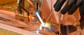
For gas-electric welding of aluminum alloys, inert gases argon and helium are used, the purity requirements of which are very high. Impurities found in the gas reduce the quality of the weld, disrupt its formation, and complicate welding. Of the various compositions of argon and helium supplied by industry for welding aluminum alloys, only argon grade A according to GOST 10157-62 and high-frequency helium grade A and B according to MRTU 51-04-23-64 can be used.
Recently, in research and in practice, much attention has been paid to the use of argon-helium mixtures and mixtures of argon with oxygen, chlorine, nitrogen and other gases as protective gases. The best results are obtained by using argon-helium mixtures, since the presence of helium allows you to increase the welding speed, increase the thermal power of the arc and increase the depth of penetration, obtain a favorable weld shape when the current value changes over a wide range, increase the stability of the arc and the density of the deposited metal. In addition, when welding with a non-consumable electrode in a mixture of argon and helium, a decrease in the number of tungsten inclusions in the weld metal was noted, and when welding with a consumable electrode, the formation of a fan-shaped plasma that covers a significant area of the metal, increasing the size of the weld pool.
Based on experience, we can conclude that for manual welding of aluminum alloys with a non-consumable electrode, argon should be used, for automatic welding with a non-consumable electrode - a mixture of 50-60% He + 50-40% Ar, and in the case of welding with a consumable electrode (automatic and semi-automatic) - mixture of 65-70% He + 35-30% Ar. Welding modes in argon-helium mixtures are different from the modes used when welding in argon (Tables 1, 2).
Table 1. Automatic welding with non-consumable electrode.
Table 2. Automatic and semi-automatic consumable electrode welding.
Welding technique
When welding aluminum and its alloys, clean and dry gloves made of split leather or similar material must be used.
Mechanized welding of butt joints without cutting edges in the lower and vertical positions is usually performed without transverse vibrations of the electrode
If there is a cutting of edges, the first seam is also performed without transverse vibrations, and subsequent ones - with small (up to 5 mm) movements of the electrode
When welding fillet welds in the lower position, the angle of inclination of the torch relative to the vertical wall is 30-45°. A fillet weld on a vertical plane is made from bottom to top, “angle forward.” Single-pass welding is performed with movements of the end of the electrode. Fillet welds of large sections on a vertical plane are made multi-pass by making narrow seams. Horizontal butt seams are also welded.
On the inside, the seam is protected with remaining or removable pads or with protective gas supplied by one of the following methods:
1- shielding gas; 2- parts to be welded; 3- plugs; 4 — connecting cables
Scheme for installing plugs in the pipeline for injecting protective gas
When welding parts with a thickness of 4 mm or more, due to the rapid cooling of the weld pool, pores form in the seam. To prevent their occurrence, step welding with reciprocating movements of the torch is used. Each step forward by 3-6 mm is accompanied by a movement back by 1.5-3 mm. This welding technique provides more effective protection and slow crystallization of the weld pool, which ultimately guarantees the absence of pores.
To reduce deformations when connecting long structures, the reverse-stage welding method is widely used.
To fill the crater, the torch is returned in the opposite direction to a distance slightly greater than the length of the crater, and at the same time the wire feed speed is reduced
When welding corner and T-joints, the welding is completed by moving the torch in the opposite direction along the seam, while simultaneously slowing down the wire feed.
An effective way to finish welding is to bring the end of the weld to lead strips, which are removed after welding
Features of working with aluminum
Electric arcs are used to connect many types of iron. This technique ensures a sufficiently high combustion temperature, resulting in high-quality penetration of plates of different thicknesses, creating reliable and hermetically sealed protection. However, welding aluminum using an inverter is considered the most difficult due to certain specific characteristics.
The first difficulty lies in the hygroscopic properties of the material, which can accumulate ambient moisture. And although this cannot be noticed in a naturally cooled state, problems will certainly arise when welding begins. When the arc is ignited and the metal is heated to elevated temperatures, moisture particles begin to evaporate from the surface and inevitably penetrate into the welding zone. The result is excessive spatter and interference that prevents a normal seam.
To prevent this phenomenon, it is enough to preheat the structure at a temperature of 150−190 degrees Celsius. In this case, you can notice intense release of moisture on the surface .
The next difficulty is the presence of an oxide film that covers all products. Its purpose is to protect the structure from the aggressive effects of an acidic environment. However, this makes processing with an inverter significantly more difficult. The main problem is associated with the large difference in melting temperatures. It is known that aluminum itself begins to melt at 500 degrees Celsius, and its oxide at 2000 degrees. To eliminate such a difference, it is enough to clean the welding site with an iron brush to ensure the required access to the metal .
Interaction with the environment ensures the correct formation of pores in the joint structure, which significantly worsens the tightness. To protect the weld pool, argon or a gas cloud is used during inverter welding.
It is no secret that pure aluminum is practically not used for the manufacture of parts, so the fillers and additional elements included in its composition can become a problem. For example, grades Al2 and Al2 contain silumin from 4 to 13%, so they are usually called limitedly weldable. Similar indicators are typical for models AM r 1 and Amr 6, where manganese is added in a proportion of 2−6%.
Requirements for inverters and materials
The basic requirements for inverters for welding aluminum alloys boil down to the following factors:
- should facilitate rapid and non-contact ignition of the arc;
- have a special burner design, consisting of: the use of special tips (the aluminum wire from the molten weld pool heats up and expands greatly);
- in the requirement for the torch channel (made of a material that reduces friction of the wire passing through the channel to the welding site).
Welding aluminum at home can be carried out using the above, and the quality of the seams will depend on the model of the apparatus and the skills that are acquired during the work.
Occurrence of cracks
The possibility of cracks occurring, in addition to the chemical composition of the alloy, is also determined by other factors that determine the magnitude and rate of development of deformation in certain periods of time. The magnitude and rate of development of metal deformation at various stages of heating and cooling depend on the welding mode, cooling conditions and the rigidity of the fastening.
Cold cracks in aluminum alloys can be not only of metallurgical origin, but also arise from improper use of certain technological operations. For example, forging welds can lead to the formation of cracks, sometimes not extending to the surface of the metal. Identifying such defects is difficult, therefore, if such operations are necessary, a thorough preliminary study is required.
Pure aluminum of the AB0000, AB000, AVOO grades is not prone to the formation of hot cracks. Crack resistance decreases with increasing silicon content and can also decrease or increase depending on the iron content. Aluminum of other grades tends to form cracks, especially when welding sheets and plates of large thickness. Suppression of the tendency to form hot cracks in alloys containing up to 0.35% Si is achieved by such an iron content that the ratio Fe: Si>= 0.5 is maintained. At a higher silicon content, a joint without cracks can be obtained when the ratio of these elements is greater than one.
Alloys of the Al-Mn system are used only with a content of 1.2-1.6% Mn (AMts alloy). This alloy is one of the best weldable alloys. Thin sheets (up to 3 mm) are welded without cracks. When welding thicker sheets, the tendency for hot cracks to form also depends on the iron and silicon content. In AMts type alloys containing more than 0.2% Fe, with a Fe:Si ratio > 1, the tendency to crack formation is close to zero. With a content of more than 0.2% Si, the Fe: Si ratio > 1 must be maintained.
Alloys of the Al-Mg system have a lower tendency to form hot cracks than alloys of the Al-Cu and Al-Si systems. The greatest tendency to crack formation is observed when welding T-test samples of an alloy containing 1-2% and 2.5-3.9% Mg when tested on cross test samples [17, 121]. To prevent the formation of cracks, it is necessary to use filler material with a high magnesium content.
Thermally hardenable alloys of the A1-Mg-Si system include the AB, AK6-1 and AKV alloys used in the USSR. Strengthening of these alloys is achieved due to the release of the Mg2Si phase during aging. Features of the weldability of such alloys are an increased tendency to form hot cracks during the welding process and softening in the heat-affected zone. Alloys containing 0.2-2% Si and 0.2-1.5% Mg exhibit the greatest tendency to form hot cracks. The tendency to form hot cracks is determined by the presence of the low-melting triple eutectics A1-Mg-Mg2Si, as well as double eutectics A1-Mg2Si and A1-Si, which expand the range of the solid-liquid state of the alloy.
Features of manual arc welding
This type of welding is used to produce products made from technically pure aluminum and silumins. Welding is carried out using direct current with reverse polarity. They use special electrodes for welding aluminum such as OZA-1, OZA-2 or OZANA, which must be dried in an oven at a temperature of 200 0C for at least 2 hours before welding. Before welding thick metal, the parts to be welded are heated to a temperature of 250 ÷ 400 0C.
Welding is performed in any spatial position at high speed. The welding current should be no more than 60 A per 1 mm Ø electrode. Metal up to 2 mm thick is welded without cutting the edges, and above that, either the edges are cut or welded with a gap (0.5 ÷ 0.7 mm).
To remove the oxide film, use AF-4A flux. Immediately after welding is completed, the seam is cleaned of slag and oxides.
