Lathe 1m61 instructions
The 1M61 universal screw-cutting lathe is designed to perform a variety of turning operations, including cutting metric, inch, modular and pitch threads.
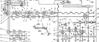
The machine can be used in machine shops for small-scale and individual production. Kinematic diagram
bed
The bed is installed on two pedestals. Between the pedestals there is a trough designed to collect chips and coolant, which flows into the reservoir of the electric pump installed in the right pedestal. The left cabinet contains the electric motor of the main drive of the machine.
Gearbox
The gearbox (Fig. 6) provides 24 spindle rotation speeds. The drive from the electric motor to the gearbox is carried out by a V-belt transmission. The rotation speed is changed by switching gears, reversing by reversing the electric motor, braking by a multi-disc electromagnetic clutch located on shaft I (see Fig. 5). Switching of three gear blocks is done with one handle I (see Fig. 3). The spindle receives twelve speeds through the overdrive gears and twelve higher speeds directly through the gear clutch. The overdrive or gear clutch is turned on by handle 3. Handle 2 provides direct or reverse rotation of the lead screw and obtains a normal or increased thread pitch. When turning, handle 2 should be in the position corresponding to cutting a right-hand thread.
Gearbox
The feed box (Fig. 7) allows you to set up the machine for thread cutting or obtain various feeds in accordance with table 15 (see section “Passport”) located on the feed box. The table shows the thread pitches, the corresponding handle positions and the required adjustments of the replacement gears. Additional threads are obtained by adjusting the gears indicated in Table 16 (gears and table are available at an additional cost). Both tables contain only normal thread pitches. The machine has the ability to obtain increased thread pitches by 16 times at 12 low levels of spindle speed, i.e. with search enabled. Switching to larger thread pitches at higher speeds is not recommended.
Apron
The apron (Fig. 8) transmits movement to the caliper from the lead screw or lead roller. The lead screw is used only when cutting threads. For all other work, the caliper should be fed exclusively from the running roller. To avoid damage, the following switching order must be strictly observed. To turn on the longitudinal feed of the caliper, handle 12 (Fig. 3) should be set to the neutral position (horizontally), handle 13 should be turned down to a fixed position and then handle 12 should be pulled out and turned down or up depending on the required direction of movement of the caliper ( according to the tables near the handles). To turn on the transverse feed of the caliper, it is necessary to set handle 12 to the neutral position, turn handle 13 up and then turn handle 12 in the extended position in the required direction.
Electrical diagram
The electric motor M1 of the main drive is controlled by the control handle of the VPV and VPN limit switches, fixed in three positions. In the neutral position of the handle, the opening contacts of the VPV (V1-10) and VPN (10-1) limit switches are closed. By turning on the automatic circuit breaker AB through the opening contacts VPV (V1-10) and VPN (10-1), the intermediate relay RP receives power and, through its normally open contact, switches to self-supply. The closed power contacts of the RP relay prepare the circuit for the electric cooling pump. The time relay RV also receives power. The opening contact of the PB relay with a time delay of 3-4 s turns off the EMT electromagnetic braking clutch. Disabling the electromagnetic braking clutch in the initial position is necessary for free rotation of the spindle. Start motor M1 in forward direction. To start the electric motor M1 in the “forward” direction (rotate the electric motor counterclockwise from the pulley side), handle 14 (see Fig. 3) is turned up. In this case, the breaking contact of the VPV travel switch (B1-10) opens (see Fig. 11) and the closing contact of the VPV (1-2) closes, the contactor KB is activated and the electric motor Ml is turned on to rotate “forward”. The break contact KB (1-4) opens, the time relay PB is de-energized, opening the normally open contact PB (11-12) and closing the break contact PB (12-13). The M1 electric motor is turned off by moving handle 14 (see Fig. 3) to the neutral position. In this case, the ERV contact (1-2) opens (see Fig. 11) and the ERV contact (B1-10) closes. The KB contactor is de-energized, the time relay PB receives power through the KB contact (1-4) and closes its closing contact PB (11-12). The electromagnetic clutch EMT is activated, receiving direct current from the selenium rectifier of the aircraft, and slows down the gearbox mechanism and the spindle. Somewhat later, with a time delay of 3-4 s, the breaking contact PB (12-13) opens, the electromagnetic clutch is turned off and the system returns to its original position. Starting the electric motor M1 in the “backward” direction is done by moving handle 14 (see Fig. 3) to the lower position. The operation of the electrical circuit is similar to the operation when starting the electric motor M1 (see Fig. 11) in the “forward” direction, only in this case the KN contactor is activated. The electric cooling pump M2 is turned on and off by the RE switch and the RP starter.
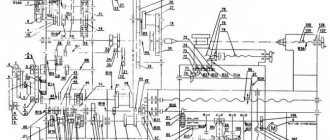
Electrical diagram of the machine 1M61
Below is a sketch of one page of the documentation “Diagram of a 1M61 screw-cutting lathe”
| < Previous | Next > |
Related materials:
- ELL 12XXX. Electric drive. Passport, Manual, Instructions, Description, Characteristics.
- ELL 4XXX. Electric drive. Passport, Manual, Instructions, Description, Characteristics.
- Drawing. 2A135. Vertical drilling machine. Kinematic scheme
- Drawing. IR800PMF4. Horizontal boring machine. Gearbox. Kinematic diagram
- Drawing. VSZ-64M. Vertical milling machine. Kinematic diagram
The following materials:
- HAAS ST-30. Turret lathe. Passport, Specifications, Manual
- HAAS ST-20. Turret lathe. Passport, Specifications, Manual
- HAAS ST-10. Turret lathe. Passport, Specifications, Manual
- 1M95. Combined machine. Passport, Characteristics, Diagram
- 1E61M. Screw-cutting lathe. Passport, Characteristics, Diagram
Previous materials:
- 2620A. Horizontal boring machine. Machine passport, kinematic diagram
- 2622A. Horizontal boring machine. Machine passport, kinematic diagram
- 2622. Horizontal boring machine. Machine passport, kinematic diagram
- 2620. Horizontal boring machine. Machine passport, kinematic diagram
- 2D450. Jig boring machine. Passport, Characteristics, Diagram, Manual
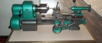
Technical characteristics of the 1m61 lathe, purpose and diagrams
Lathe brand 1M61: characteristics, operating capabilities, control, main mechanisms, dimensions, purpose and scope of use.
The 1M61 lathe was created in the 1970s at a machine tool factory in Yerevan. Such machines gained the greatest popularity in small factories with insignificant production scales. The machine was most suitable for creating several copies of products.
1M61s were also installed at industrial and agricultural enterprises, and were used in large-scale production at defense factories.
Characteristics of the 1M61 lathe
- the design nuances of the mechanism make it possible to process products up to 1 m long, and the maximum length of the surface of the workpiece reaches 65 cm;
- the height of the holder of parts inserted into the tool holder should not be more than 2.5 cm;
- spindle turning at 24 speeds in forward and reverse motion. The speed range varies from 12.5 to 1600 rpm. The diameter of the hole in it is 3.5 cm, and the diameter of the products is 3.2 cm;
- due to the specific design, the quill is capable of moving at a distance of up to 10 cm;
- the maximum diameter of the workpiece being sharpened above the support is 16 cm;
- the machine caliper is capable of moving transversely up to 20 cm, and lengthwise up to 60 cm;
- the maximum diameter of the workpiece to be turned above the bed is 32 cm;
- incisor height – 2.5 cm;
- movement of the caliper carriage – 60 cm, slide – 120 cm;
- The power of the main electric motor of the machine is 4 kW, and the power of the cooling electric pump is 0.12 kW.
Technical capabilities
By introducing more than twenty control mechanisms into the device, the machine operator has the opportunity to solve many problems:
- determine the rotational period of the spindle, establish the forward and reverse movement of the spindle assembly;
- make a choice of the required type of thread;
- engage the lead screw;
- in certain situations, start and disable the safety clutch;
- set the caliper in motion;
- regulate feed settings;
- activating reverse rotation of the screw, setting the required thread parameters.
The electric motor of the machine is capable of performing work in reverse mode, and the spindle speed range is adjusted by the gearbox. In addition, the control system of the turning machine makes it possible to supply cooled substances to the units at the right time, engage and disengage the cutting rack. It can also fix and change the position of the cutter head, and illuminate the work area of the screw-cutting machine. The machine has a load level indicator.
Thanks to the feed box, the machine operator has the opportunity to set the required parameters when making threads. The technical description for the lathe provides information not only about the size of the products, but also about what feed will be best for performing a specific task.
Machine control
Adjustment of the devices is carried out using a set of working tools. The quill makes the flywheel move. It is fixed using a specially designed stop located in the tailstock, secured to the frame with a specific handle. The handles located at the front of the frame are used to regulate specific work processes:
- turning on the roller or screw;
- selecting the rotational frequency of the spindle assembly;
- feed setting;
- a button that activates the mechanism for coupling and uncoupling the rack to create threads using the gear shaft;
- movement of the top of the caliper;
- starting and disengaging the split screw nut;
- selection of thread cutting type;
- disconnecting and starting the safety clutch;
- determining thread settings and starting screw reverse;
- message about the degree of load;
- starting direct and reverse rotation of the spindle head;
- handle for turning and fastening the cutter head;
- button to start the electric pump that supplies cooled liquid.
- button to start power supply and zone lighting of the work area.
The design of the machine provides a special lever that ensures the fixation of the machine carriage when performing work on the end of products.
Controls
The operator can control the screw-cutting lathe model 1M61 and control the operation of its components using a number of working parts. In particular, the movement of the quill is set by a flywheel, and this unit is fixed in the tailstock thanks to a special stop. The tailstock itself is fixed on the frame guides using the appropriate handle. The machine carriage also requires reliable fixation when performing end work, which is ensured by a separate screw.
Controls
The handles located on the front part of the 1M61 frame are used to control such processes in the operation of equipment as:
- selection of spindle speed;
- starting the rotation of the lead screw or roller;
- movement of the upper part of the caliper;
- feed parameters;
- setting the parameters of the thread to be cut and turning on the reverse of the lead screw;
- turning on and off the lead screw nut;
- turning on and off the safety clutch;
- selection of the type of thread to be cut;
- enabling direct and reverse rotation of the spindle head.
The 1M61 model machine also has a number of other controls. This:
- a button used to engage and disengage the thread cutting rack with the pinion shaft;
- handle for turning and securing the cutting head;
- load degree indicator;
- button to turn on the electrical power and local lighting of the work area;
- button to start the electric pump that supplies coolant.
Kinematic diagram of 1M61 (click to enlarge)
Gearboxes and gearboxes
The gearbox is designed to select the spindle rotation interval. It includes 3 elements:
- Electrical engine.
- A row of gears.
- Gear mechanism.
The total number of speeds for the spindle is 24. The machine operator selects 12 of them directly through the clutch, and another 12 through the selection gears. The machine is controlled by a master using 3 handles for:
- gear shifting;
- changes in the rotational stroke of the screw (during the thread creation process);
- starting the search and clutch.
The gearbox transmits movement from the gearbox to the feedbox and serves to adjust the feeds to the type of thread being cut.
Purpose and scope of screw-cutting lathe
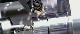
The 1M61 machine is used for turning products from the outside and inside, having a curved and stepped profile in the axial section. Makes it possible to use drills, cutters and taps, and perform the following types of metalworking:
- Cutting products.
- Reaming and drilling.
- Turning of blanks.
- Creation of different types of carvings.
In machine shops, a 1M61P screw-cutting machine can be used to perform various turning operations, including the creation of threads of various types in single and small-scale production.
Screw-cutting lathe 1M61
The 1M61 lathe was produced from 1975 to 1992 in Yerevan. According to the technical characteristics, the 1M61 machine is designed for processing parts d up to 320 mm with a variety of surfaces. Threads are also cut on the machine. They were installed at agricultural and industrial enterprises, and were used in large-scale production at defense factories.
On 1M61 screw-cutting lathes, in addition to thread cutting, you can produce:
- grinding of various surfaces;
- trimming parts;
- grooving;
- drilling, countersinking;
- cutting parts and other work.
1M61. The passport includes a manual for use (1M61.00.000 RE), a description of the unit, instructions for use and machine standards.
Download the passport (operating instructions) of the 1M61 machine
Lathe 1M61, explanation:
- 1 group of metalworking machines - lathe;
- M generation mechanism (A, B, C, D, K, L, M);
- 6 type of turning row – screw-cutting lathe;
- 1 distance to the bed – 170mm
Kinematic diagram of the 1M61 machine
Design features
According to its technical characteristics, the 1M61 lathe is assigned to the “N” accuracy class. The electric motor of the unit is capable of operating in a reversible range. The spindle rotation speed is comparable to the possibility of changing the functioning of the gearbox and aggregating diverse gears with each other.
The unit in question can use cutters, drills and taps of various configurations. Such universalization allows you to perform a whole range of technological manipulations, including external turning, reaming, drilling, cutting and similar operations.
Transverse and longitudinal movements are made using a roller and a screw; a flywheel is located on its front part. The lead screw is used when cutting threads; the parameters of the apron make it possible to block the aggregation of caliper movements. This eliminates the risk of moving the caliper with the roller and screw.
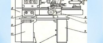
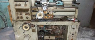
Main components of the 1M61 screw-cutting lathe
Main components of the machine
- The basic unit of the machine is the bed (1) , which has the largest mass among other component structures. It is based on the platform and secured with bolts. The bed has 2 guides, one is dovetail shaped and the other is prismatic shaped. Thanks to these shapes of guides and adjustable wedges, the caliper is held rigidly on the frame.
- On the left side of the 1M61 lathe there is a headstock (2). It is installed in such a way in the grooves that it can be rotated several degrees, that is, the center can be shifted relative to the axis. By this, during processing, a part configuration with a flat cone is achieved.
- The gearbox (3) is located in the headstock, and the control levers are located outside. A set of interchangeable gears is mounted on the end of the headstock, on which the gears are changed before threading. A spindle assembly is placed in the gearbox and by connecting certain gears on blocks, the spindle rotates at a speed of 16 to 2000 rpm.
The cabinet on the left houses the main drive motor of the 1M61 lathe and enables forward and reverse rotation of the spindle.
- The tailstock (7) is located on the right side of the frame. A quill with a Morse taper 4 is mounted into it; various tools are inserted there:
- drill;
- taps;
- dies;
- center.
The rear headstock 1M61 moves along the frame and is securely fastened with a mechanical clamp. It has a quill stroke of 100 mm and, in addition to certain processing operations, it serves to press a long workpiece through a rotating center.
- There is an apron (4) located at the bottom of the machine in the middle. A shaft and screw pass through it. The shaft serves to accelerate the movement of the caliper, and the screw for cutting threads.
- A caliper (6) is located above the apron; a tool holder and a slide for turning conical surfaces are attached to it
- On the left side of the headstock there is a feed box (5), and on it there are levers and feed switches.
- An electrical cabinet (8) is located behind the machine; controls in the form of automatic machines are mounted on it.
- At the bottom of the machine, a water pump is mounted in a pan, and a lubricant and cooling liquid (coolant) is poured into a trough there.
- The screen (9) protects the turner from chips and liquid that splashes during work.
Threading machine setting table
Cutting is done using dies, taps and cutters. Let's consider cutting with cutters.
To cut the required metal thread, you need to install the gears in the feed box and speed box so that the cutter in the tool holder cuts the profile in one revolution of the spindle. To do this, set the appropriate feed rate and speed on the gearbox and feed box according to the table presented above.
Threaded cutters must be sharpened taking into account the material of the workpiece being processed.
- The upper part of the cutter (rake angle) can be from 0 to -15 degrees, depending on the material, the softer the material, the larger the angle can be. If the thread is cut on a workpiece made of ordinary carbon steel, then the angle should be 0 degrees. And if it is made of alloy steel, then the angle is made negative up to 10 degrees.
- The thread cutter must form a profile, so its angle must match the thread. Its types are presented on the top table, which can be used when sharpening certain cutters.
- The back angle should not interfere with cutting and therefore is made the same on both sides, or slightly smaller. For example, the angle of the profile is 4 degrees, then the rear angle of the cutter should be 3.5-3.8 degrees.
Electrical diagram
An asynchronous electric motor of type AO2-61-4 13 kW is the main unit that drives the system. Just press the “Start” button for this device to start working. With the help of a friction clutch, activated from the handle, similar parts of the mechanism are controlled. Depending on whether the clutch is turned on or off, the mechanism reacts differently to the start of operation.
1.1 kW – engine power responsible for working feeds.
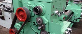
Gearbox 1M61
Gearbox of machine 1M61
The gearbox contains inside a spindle assembly and blocks of shafts and gears; speed is supplied to them by means of V-belts and pulleys from a reversible engine. According to the passport, due to the search unit in the gearbox, 12 different spindle revolutions are created, and another 12 are transmitted through a stepped clutch located in the spindle assembly.
There are three levers on the gearbox panel. One of them switches the gears on the gear block, the second switches on the overdrive and stepped gear coupling, and the third lever transmits the engagement of the gears to the screw when cutting threads. An electric clutch is installed on the gearbox spindle to brake the spindle, and this is a feature of the machine.
In conclusion, it should be noted that in our time of new technologies, machines with such passport data, despite new, improved technologies, still occupy their rightful place among lathes for metal-cutting equipment.
1E61M Location of the main components and controls of the machine
Location of machine controls 1e61m
List of controls for the 1E61M lathe
- Turning on the electric oil pump and connecting to an external power supply
- Switching on the emulsion electric pump
- Stop for starting, stopping and reversing the spindle
- Stop for starting, stopping and reversing the spindle
- Switching spindle speeds
- Enabling headstock override
- Snaffle and mechanism for eightfold increase in thread pitches
- Shifting Norton Cone Gears
- Inclusion of metric and modular, imperial and pitch or precision threads
- Multiplying mechanism for feeds or thread pitches
- Turning on the lead screw or lead shaft
- Handwheel for manual longitudinal movement of the carriage
- Moving the cross slide
- Moving the upper caliper slide
- Fastening the cutting head
- Enabling longitudinal or transverse feeds
- Engaging the lead screw nut
- Turning on and off the falling worm
- Attaching the support carriage to the frame
- Attaching the tailstock to the frame
- Moving the tailstock quill
- Tailstock quill fastening
- Transverse displacement of the tailstock housing
- Automatic stop for longitudinal feed
- Automatic cross feed stop
- Rigid fixation of the lead screw nut
- Turning on local lighting
- Quick removal of the cutter from the workpiece
The main components of a lathe and their purpose
The source of movement in the machine is an electric motor, which transmits rotation to the spindle through a gearbox (gearbox), and from the spindle through a set of replaceable gears and a feedbox, rotation is transmitted to the lead screw m (for thread cutting) or to the run shaft N (for other turning operations). operations).
Spindle braking is carried out countercurrently.
The short workpieces are clamped in the jaw chuck, and the right end of the long workpiece is supported by a center located in the tailstock quill.
The tailstock is also used to secure and feed drills and other axial tools.
The support serves to carry out movements of the cutter fixed in the tool holder in the longitudinal and transverse directions.
The apron mechanism converts the rotational movement of the lead shaft or lead screw into the translational movement of the caliper.
Manufacturer information
This equipment was created at a machine tool factory in Yerevan. At the moment, this enterprise is called the Yerevan Machine Tool Association and produces high-precision screw-cutting lathes with a processing diameter of 500 mm.
Technical series
The technical range of screw-cutting lathes produced at this plant is extensive, and there are several models that are reliable and in demand among manufacturers. Each sample of the technical series has its own characteristics of operation and accuracy.
Main technical characteristics
Each part has its own characteristics, functional purpose and technical characteristics that affect the overall operation of the equipment.
Spindle
This node has the following characteristics:
- the diametrical size of the hole passing through is 35 mm;
- the largest diameter rod that fits into the hole is 32 mm;
- number of stages of forward and reverse rotation – 24;
- There is spindle braking.
Feeds and threads
Technical characteristics for these parameters:
- maximum caliper movement – 200 mm;
- longitudinal movement of the carriage – 600 mm;
- maximum movement of the cutting slide – 120 mm;
- number of steps – 17.
Caliper
A tool holder and special slides are attached to this structure, which are used for turning conical surfaces.
The support moves in the transverse and longitudinal direction. The upper part is called a sled and can move 12 cm.
Landing and connecting bases of the machine. Spindle
A spindle is a shaft that is necessary for securing the workpiece being processed. The spindle has holes in which the rods are processed.
The neck of the element itself has a conical or cylindrical shape. The spindle ensures precision processing; it must have durability, reliability and acceptable heating parameters.
Kinematic diagram
Headstock
The headstock or spindle headstock performs the main function of the machine; it transmits torque from the electric motor.
The spindle is located on the inside of this structure. The gearbox handle is located on the outside of both walls.
Tailstock
Also called persistent. The main function of this structural component is to fix the workpiece. Also, this design is designed for installing various drills and other tools.
Brake clutch
This is a magnetic part, one of the most important design elements. Responsible for slowing down speed during operation.
bed
The cast iron base of the entire structure, to which all other parts of the machine are attached. It is made by injection molding, which reduces machine vibrations. To the right of the bracket are parts with electrical equipment.
Gearbox
Using the gearbox, a specific rotation speed of the spindle assembly is set. The spindle itself can operate at 24 speeds. 12 of them are adjusted from the machine gears, and the other 12 are adjusted through a gear coupling.
Feed box with 3 handles
This is a classic option with which you can regulate major changes in the operation of the machine.
Feed box with 4 handles
In this case, there are 4 handles with which you can perform the following actions:
- setting the type of thread and feed;
- adjustment of thread size and feed;
- adjustment of thread pitch and feed;
- turning on the lead screw and shaft.
Gearbox guitar
This component serves to transmit movement from the gearbox to the feed box, as well as to adjust feed rates for a specific type of thread being cut.
The movement is transmitted depending on whether a metric, inch, modular or pitch thread is cut on the workpiece.
Electrical equipment and electrical circuit of the machine
The 1M61 lathe has been used in small-scale production for decades.
It is equipped with all the necessary components that ensure its versatility, as well as reliability and durability.
How the machine model 1M61 works
The basis of the lathe model 1M61 is made up of ten elements, which include:
- supporting frame;
- gearbox;
- gear box;
- gearbox;
- apron;
- caliper;
- tailstock;
- electrical equipment system;
- a screen that performs a protective function;
- a system that provides cooling of the tool and processing area.
Main components of the machine
According to its technical characteristics, the machine model 1M61 belongs to the “N” accuracy category. The machine's electric motor can operate in reverse mode. The rotation speed of the equipment spindle is changed by means of a gearbox in which gears with different parameters are meshed.
On the 1M61 model lathe, working tools such as cutters, drills, reamers and taps can be used. This makes it possible to perform a whole range of technological operations: internal and external turning, drilling, reaming, threading, cutting, etc.
An apron is responsible for the transverse and longitudinal movements of the machine support, carried out using a lead screw and a lead roller, on the front of which there is a control flywheel. The 1M61 lead screw is used only when a thread cutting operation is performed, otherwise only the lead roller is used. The characteristics of the apron make it possible to block the combination of the longitudinal and transverse movements of the caliper, which reduces to zero the risk of the lead screw and the roller being put into operation simultaneously.