Characteristics
Price request
I need advice
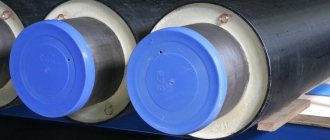
Sliding supports are pipeline elements used to fix polyurethane foam pipes with a galvanized steel shell in a given position. They are used for laying pipelines of above-ground and channel types related to heat and water supply systems.
Sliding supports for pipes do not have thermal insulation; the fastening of pipes to these metal structures does not provide for their rigid fixation with a welded joint.
Application of supports for pipes in polyurethane foam
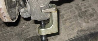
Sliding support designs easily support designated sections of pipelines while absorbing the pressure of vertical loads that are created by temperature or pressure fluctuations within the system.
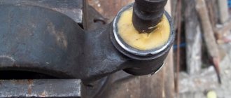
Pipes in PPU insulation are laid on a support. The pipe is fixed by tightening it with clamps.
Protection of the outer shell from damage during operation is ensured by laying damping material (polyethylene, rubber) between the outer shell of the pipe and the lower part of the heating network pipeline support.
The pipes installed on sliding supports are not rigidly attached, but have the ability to freely move in a longitudinal position. This allows the pipes to avoid sagging or excessive stress when changing modes in the operation of the heating main.
Advantages of pipeline supports with polyurethane foam insulation
PPU supports are used for the construction of pipelines from pipes insulated with polyurethane foam. They provide reliable placement of pipes, rigidly fixing their position along the axis. The distance between the supports is determined by the features of the local topography and the placement of compensators designed to absorb fluctuations in pipe lengths when temperature changes.
Some enterprises produce metal supports for pipes in polyurethane foam that do not have an insulating layer. Their cost is lower than polyurethane foam supports, but they do not have the advantages that products with thermal insulation have:
- improved protection against moisture from the atmosphere and soil;
- high resistance to mechanical loads;
- protection of pipelines from minor changes in shape;
- chemically neutral, low flammability.
Polyurethane foam is suitable for insulating any material. It is suitable for concrete, glass, metal, wood, plastic, etc. It is not destroyed by temperature changes and retains its quality for decades. Those wishing to order high-quality polyurethane foam supports for pipeline construction, our company can always supply the required quantity. All products are certified, have a guarantee, and delivery is guaranteed
Designation, weight, diameter, width and weight of supports.
| Designation | Pipe diameter | Clamp DN, mm | Width B, mm | Maximum distance between supports | Support weight, kg | Price including VAT,RUB — Rubles |
| SPO 57/125.100 | 57 | 130 | 128 | 5 | 2,7 | 419,43 |
| SPO 57/140.100 | 57 | 145 | 128 | 5 | 2,9 | 450,12 |
| SPO 76/140.100 | 76 | 145 | 138 | 5,5 | 3,1 | 480,81 |
| SPO 76/160.100 | 76 | 165 | 138 | 5,5 | 3,3 | 501,27 |
| SPO 89/160.100 | 89 | 165 | 145 | 6 | 3,3 | 511,5 |
| SPO 89/160.100 | 89 | 185 | 145 | 6 | 3,3 | 521,73 |
| SPO 108/180.100 | 108 | 185 | 154 | 7 | 3,4 | 531,96 |
| SPO 108/200.100 | 108 | 205 | 154 | 7 | 3,5 | 542,19 |
| SPO 108/250.100 | 108 | 255 | 154 | 7 | 3,7 | 562,65 |
| SPO 133/200.100 | 133 | 205 | 166 | 8 | 3,7 | 572,88 |
| SPO 133/225.100 | 133 | 230 | 166 | 8 | 3,8 | 583,11 |
| SPO133/250.100 | 133 | 255 | 166 | 8 | 3,9 | 603,57 |
| SPO 159/250.100 | 159 | 255 | 180 | 9 | 4,6 | 705,87 |
| SPO 159/315.100 | 159 | 320 | 180 | 9 | 4,8 | 736,56 |
| SPO 57/125.150 | 57 | 130 | 175 | 5 | 3,5 | 501,27 |
| SPO 57/140.150 | 57 | 145 | 175 | 5 | 3,6 | 511,5 |
| SPO 76/140.150 | 76 | 145 | 188 | 5,5 | 3,7 | 531,96 |
| SPO 76/160.150 | 76 | 165 | 188 | 5,5 | 3,9 | 562,65 |
| SPO 89/160.150 | 89 | 165 | 195 | 6 | 4 | 572,88 |
| SPO 89/160.150 | 89 | 185 | 195 | 6 | 4 | 583,11 |
| SPO 108/180.150 | 108 | 185 | 204 | 7 | 4,1 | 593,34 |
| SPO 108/200.150 | 108 | 205 | 204 | 7 | 4,2 | 603,57 |
| SPO 108/250.150 | 108 | 255 | 204 | 7 | 4,5 | 644,49 |
| SPO 133/200.150 | 133 | 205 | 216 | 8 | 4,4 | 634,26 |
| SPO 133/225.150 | 133 | 230 | 216 | 8 | 4,7 | 675,18 |
| SPO 133/250.150 | 133 | 255 | 216 | 8 | 4,7 | 685,41 |
| SPO 159/250.150 | 159 | 255 | 230 | 9 | 5,6 | 797,94 |
| SPO 159/315.150 | 159 | 320 | 230 | 9 | 5,6 | 808,17 |
| SPO 57/125.200 | 57 | 130 | 228 | 5 | 4,5 | 552,42 |
| SPO 57/140.200 | 57 | 145 | 228 | 5 | 4,5 | 562,65 |
| SPO 76/140.200 | 76 | 145 | 238 | 5,5 | 4,6 | 572,88 |
| SPO 76/160.200 | 76 | 165 | 238 | 5,5 | 4,9 | 603,57 |
| SPO 89/160.200 | 89 | 165 | 245 | 6 | 5 | 613,8 |
| SPO 89/160.200 | 89 | 185 | 245 | 6 | 5 | 624,03 |
| SPO 108/180.200 | 108 | 185 | 254 | 7 | 5,1 | 634,26 |
| SPO 108/200.200 | 108 | 205 | 254 | 7 | 5,1 | 644,49 |
| SPO 108/250.200 | 108 | 255 | 254 | 7 | 5,3 | 654,72 |
| SPO 133/200.200 | 133 | 205 | 266 | 8 | 5,4 | 664,95 |
| SPO 133/225.200 | 133 | 230 | 266 | 8 | 5,7 | 695,64 |
| SPO 133/250.200 | 133 | 255 | 266 | 8 | 5,5 | 675,18 |
| SPO 159/250.200 | 159 | 255 | 280 | 9 | 6,6 | 808,17 |
| SPO 159/315.200 | 159 | 320 | 280 | 9 | 5,8 | 705,87 |
*The weight of the support is indicated taking into account the metal deposited during welding
PPU pipeline supports: varieties
On the company's official website you can order all types of pipeline supports with polyurethane foam insulation. They can be divided into the following categories:
- fixed, ensuring rigid fixation of the pipe on the support, excluding any change in position in the horizontal and vertical position, can be mounted in reinforced concrete frames;
- sliding (movable), allowing the pipe to move along the support during its linear elongation, ensure uniform distribution of mechanical load and thermal deformation.
Sliding supports for pipes in PP insulation make it possible to partially dampen vibrations and maintain the integrity of the pipes in the event of ground subsidence and seismic tremors. The qualities of polyurethane foam are very important, allowing:
- provide high heat and sound insulation with high material density and elasticity and flexibility with low density;
- adjust the thickness of the material to better suit the climatic conditions of the area and the temperature of the transported medium.
The protective polyurethane foam layer can be double or single. Double protection improves the protective characteristics of the layer, reducing thermal deformation and heat loss. PPU insulation lasts for more than 30 years, maintaining its characteristics throughout its operation.
Production
To manufacture polyurethane foam supports for pipelines, hoists of different brands are used. The choice of material is influenced by the expected operating conditions and design documentation. Supports are required for laying cold water and heating water pipelines; they can be used when installing gas and oil pipelines.
The company produces 2 types of products:
- intended for laying PPU-PE pipes (used for underground installation, in a channelless manner);
- intended for installation of PPU-OTs pipelines (used for above-ground installation).
The products offered by the Spetsneftemash enterprise are suitable for laying PPU PE and OC pipes. They are manufactured in accordance with the requirements of GOST 30732. The cost of products depends on the size, type of metal products, type of insulation, and order volume. It is possible to order non-standard designs. Pickup or delivery to any region is possible. Email
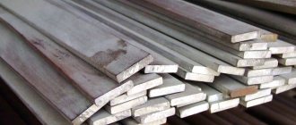
Steel grades used:
- St3,
- St20,
- 09G2S.
Specifications
Supports in a polyurethane foam shell are used for the construction and reconstruction of technological networks with media circulating in them that meet the following characteristics:
- with a maximum working pressure of up to 25 MPa;
- maximum long-term temperature up to +140 °C;
- maximum short-term temperature up to +150 °C.
The temperature range supplied by the network must be in the range from +70 to +150 °C.
| Diameter of steel pipe d, mm | Diameter of PE shell, mm | Weight, kg | Width of supporting surface B, mm | Support surface length L, mm |
| 32 | 125 | 7,80 | 100 | 320 |
| 38 | 125 | 7,80 | 100 | 320 |
| 45 | 125 | 7,80 | 100 | 320 |
| 57 | 125 | 7,80 | 100 | 320 |
| 76 | 140 | 8,06 | 100 | 320 |
| 89 | 160 | 8,58 | 100 | 320 |
| 108 | 180 | 9,11 | 100 | 320 |
| 133 | 225 | 14,83 | 140 | 470 |
| 159 | 250 | 15,65 | 140 | 470 |
| 219 | 315 | 53,43 | 280 | 670 |
| 273 | 400 | 53,83 | 280 | 670 |
| 325 | 450 | 60,95 | 280 | 670 |
| 426 | 560 | 81,84 | 280 | 670 |
| 530 | 710 | 85,17 | 280 | 670 |
| 630 | 800 | 158,27 | 600 | 770 |
| 720 | 900 | 165,22 | 600 | 770 |
| 820 | 1000 | 208,61 | 600 | 770 |
| 920 | 1200 | 260,90 | 600 | 770 |
| 1020 | 1200 | 260,90 | 600 | 770 |
MN 4008-62 Pipeline parts. Welded fixed and sliding supports for steel pipelines
NORMAL MECHANICAL ENGINEERING
Pipe parts
WELDED FIXED AND SLIDING SUPPORTS FOR STEEL PIPELINES
MN 4008-62
| USSR Committee of Standards, Measures and Measuring Instruments under the Council of Ministers of the USSR VNIINMASH | NORMAL MECHANICAL ENGINEERING | MN 4008-62 |
| Pipe parts WELDED FIXED AND SLIDING SUPPORTS FOR STEEL PIPELINES |
This standard applies to fixed welded supports designed to absorb axial compensation forces of the pipeline and frictional forces of sliding supports, and sliding supports for carbon steel pipelines with a working medium temperature of up to 300 °C.
An example of designation of a fixed pipeline support Dн
= 219 mm and
H
= 95 mm:
Support 219-95 MN 4008-62
The same, sliding:
Support S-219-95 MN 4008-62
| Developed by the Leningrad Branch of the Institute, ORGENERGOSTROY | Approved by the All-Union Scientific Research Institute for Normalization in Mechanical Engineering (VNIINMASH) 31/ VII 1962 | Date of introduction 1/1 1964 |
Table 1
Dimensions in mm
| Cipher | Pipeline outer diameter, D n | H (additional deviation ±5) | H1 | H2 | IN | b (additional deviation ±0.5) | B1 | s | TO | K1 | Fixed | Sliding | ||||||||||||||||
| Fixed | Sliding | L | l (additional deactivation -1) | l 1 | t | Quantity, n | Weight, kg | Applicability | L | l (additional deactivation -1) | l 1 | t | Quantity, n | Weight, kg | Applicability | |||||||||||||
| 57-95* | — | 57; 60 | 95 | 99 | 124 | 54 | 34 | 26 | 4 | 4 | 5 | 60 | 40 | 45 | 40 | 1 | 0,598 | — | ||||||||||
| 68-95* | 68 | 104 | 129 | 62 | 42 | 0,677 | ||||||||||||||||||||||
| 76-95* | 76 | 133 | 68 | 48 | 35 | 0,680 | ||||||||||||||||||||||
| 83-95* | 83 | 136 | 70 | 50 | 70 | 50 | 55 | 50 | 0,822 | |||||||||||||||||||
| 89-95* | 89 | 140 | 75 | 55 | 0,835 | |||||||||||||||||||||||
| 102-95 | S-102-95 | 102 | 146 | 85 | 65 | 140 | 120 | 125 | 60 | 2 | 1,594 | 70 | 50 | 55 | 50 | 1 | 0,930 | |||||||||||
| 108-95 | S-108-95 | 108 | 149 | 1,614 | 0,934 | |||||||||||||||||||||||
| 114-95 | S-114-95 | 114 | 152 | |||||||||||||||||||||||||
| 127-95 | S-127-95 | 127 | 109 | 158 | 100 | 80 | 150 | 130 | 140 | 65 | 1,869 | 80 | 60 | 65 | 60 | 1,202 | ||||||||||||
| 133-95 | S-133-95 | 133 | 114 | 162 | 110 | 90 | 2,029 | 1,281 | ||||||||||||||||||||
| 140-95 | S-140-95 | 140 | 165 | 2,114 | 1,359 | |||||||||||||||||||||||
| 152-95 | S-152-95 | 152 | 171 | 130 | 110 | 2,308 | 1,497 | |||||||||||||||||||||
| 159-95 | S-159-95 | 159 | 175 | 170 | 150 | 155 | 50 | 3 | 2,540 | 1,503 | ||||||||||||||||||
| 168-95 | S-168-95 | 168 | 126 | 179 | 160 | 130 | 6 | 6 | 6 | 185 | 155 | 4,599 | 110 | 80 | 85 | 40 | 2 | 3,222 | ||||||||||
| 180-95 | S-180-95 | 180 | 185 | 4,637 | 3,238 | |||||||||||||||||||||||
| 194-95 | S-194-95 | 194 | 192 | 175 | 145 | 210 | 180 | 190 | 60 | 5,454 | 3,329 | |||||||||||||||||
| 219-95 | S-219-95 | 219 | 136 | 205 | 200 | 170 | 6,174 | 125 | 95 | 105 | 50 | 4,194 | ||||||||||||||||
| 245-95 | S-245-95 | 245 | 218 | 210 | 180 | 240 | 210 | 205 | 50 | 4 | 6,966 | 4,380 | ||||||||||||||||
| 273-95 | S-273-95 | 273 | 232 | 235 | 205 | 260 | 230 | 245 | 60 | 7,958 | 4,724 | |||||||||||||||||
| 299-95 | S-299-95 | 299 | 146 | 245 | 255 | 225 | 260 | 230 | 245 | 60 | 4 | 8,864 | 200 | 170 | 170 | 55 | 3 | 7,249 | ||||||||||
| 325-95 | S-325-95 | 325 | 258 | 265 | 235 | 70 | 320 | 290 | 305 | 5 | 10,29 | 210 | 180 | 180 | 60 | 7,472 | ||||||||||||
| 377-95 | S-377-95 | 377 | 284 | 295 | 265 | 360 | 330 | 335 | 55 | 6 | 11,93 | 220 | 190 | 205 | 50 | 4 | 8,107 | |||||||||||
| 426-95 | S-426-95 | 426 | 166 | 308 | 345 | 315 | 420 | 390 | 395 | 65 | 16,20 | 10,05 | ||||||||||||||||
| 480-95 | S-480-95 | 478; 480 | 176 | 335 | 395 | 365 | 450 | 420 | 425 | 60 | 7 | 19,31 | 11,34 | |||||||||||||||
| 530-95 | S-530-95 | 529; 530 | 360 | 415 | 385 | 20,02 | 240 | 210 | 12,44 | |||||||||||||||||||
| 630-95 | S-630-95 | 630 | 158 | 410 | 465 | 425 | 8 | 8 | 8 | 500 | 460 | 460 | 65 | 29,65 | 280 | 240 | 245 | 60 | 19,17 | |||||||||
| 720-95 | S-720-95 | 720 | 148 | 455 | 420 | 380 | 520 | 480 | 505 | 50 | 10 | 27,75 | 12,65 | |||||||||||||||
| 820-95 | S-820-95 | 820 | 138 | 505 | 26,94 | 180 | 140 | 140 | 65 | 2 | 12,12 | |||||||||||||||||
| 920-95 | S-920-95 | 920 | 555 | 26,91 | 12,24 | |||||||||||||||||||||||
| 1020-95 | S-1020-95 | 1020 | 140 | 605 | 450 | 400 | 10 | 10 | 12 | 530 | 480 | 35,88 | 220 | 170 | 170 | 55 | 3 | 18,36 | ||||||||||
| 1120-95 | S-1120-95 | 1120 | 130 | 655 | 34,59 | 17,57 | ||||||||||||||||||||||
| 1220-95 | S-1220-95 | 1220 | 150 | 705 | 550 | 500 | 42,74 | 22,10 | ||||||||||||||||||||
| 1420-95 | S-1420-95 | 1420 | 140 | 805 | 41,52 | 21,57 | ||||||||||||||||||||||
| 1620-95 | S-1620-95 | 1620 | 905 | 560 | 512 | 43,81 | 21,96 | |||||||||||||||||||||
| 168-145 | S-168-145 | 168 | 145 | 176 | 229 | 160 | 130 | 60 | 6 | 6 | 6 | 185 | 155 | 155 | 3 | 5,832 | 110 | 80 | 85 | 40 | 2 | 4,050 | ||||||
| 180-145 | S-180-145 | 180 | 235 | 5,870 | 4,101 | |||||||||||||||||||||||
| 194-145 | S-194-145 | 194 | 242 | 175 | 145 | 210 | 180 | 190 | 60 | 6,885 | 4,303 | |||||||||||||||||
| 219-145 | S-219-145 | 219 | 186 | 255 | 200 | 170 | 7,736 | 125 | 95 | 105 | 50 | 5,384 | ||||||||||||||||
| 245-145 | S-245-145 | 245 | 186 | 268 | 210 | 180 | 240 | 210 | 205 | 50 | 4 | 8,729 | 125 | 95 | 105 | 50 | 2 | 5,628 | ||||||||||
| 273-145 | S-273-145 | 273 | 282 | 235 | 205 | 260 | 230 | 245 | 60 | 9,994 | 6,054 | |||||||||||||||||
| 299-145 | S-299-145 | 299 | 196 | 295 | 255 | 225 | 10,88 | 200 | 170 | 170 | 55 | 3 | 9,074 | |||||||||||||||
| 325-145 | S-325-145 | 325 | 308 | 265 | 235 | 120 | 320 | 290 | 305 | 5 | 12,47 | 210 | 180 | 190 | 60 | 9,154 | ||||||||||||
| 377-145 | S-377-145 | 377 | 334 | 295 | 265 | 360 | 330 | 335 | 55 | 6 | 14,48 | 220 | 190 | 205 | 50 | 4 | 10,07 | |||||||||||
| 426-145 | S-426-145 | 426 | 216 | 358 | 345 | 315 | 420 | 390 | 395 | 65 | 19,32 | 12,10 | ||||||||||||||||
| 480-145 | S-480-145 | 478; 480 | 226 | 385 | 395 | 365 | 450 | 420 | 425 | 60 | 7 | 22,83 | 13,68 | |||||||||||||||
| 530-145 | S-530-145 | 529; 530 | 410 | 415 | 385 | 23,58 | 240 | 210 | 15,19 | |||||||||||||||||||
| 630-145 | S-630-145 | 630 | 208 | 460 | 465 | 425 | 8 | 8 | 8 | 500 | 460 | 460 | 65 | 35,21 | 280 | 240 | 245 | 60 | 23,16 | |||||||||
| 720-145 | S-720-145 | 720 | 198 | 505 | 420 | 380 | 520 | 480 | 505 | 50 | 10 | 32,95 | 15,72 | |||||||||||||||
| 820-145 | S-820-145 | 820 | 188 | 555 | 32,05 | 170 | 140 | 140 | 65 | 2 | 15,16 | |||||||||||||||||
| 920-145 | S-920-145 | 920 | 605 | 32,35 | 15,31 | |||||||||||||||||||||||
| 1020-145 | S-1020-145 | 1020 | 190 | 655 | 450 | 400 | 10 | 10 | 12 | 530 | 42,62 | 210 | 170 | 170 | 55 | 3 | 22,92 | |||||||||||
| 1120-145 | S-1120-145 | 1120 | 180 | 705 | 41,38 | 21,99 | ||||||||||||||||||||||
| 1220-145 | S-1220-145 | 1220 | 200 | 755 | 550 | 500 | 50,29 | 27,46 | ||||||||||||||||||||
| 1420-145 | S-1420-145 | 1420 | 190 | 855 | 49,05 | 26,68 | ||||||||||||||||||||||
| 1620-145 | S-1620-145 | 1620 | 955 | 560 | 512 | 51,64 | 27,01 | |||||||||||||||||||||
Notes:
1. Supports whose code is marked with * are also used as sliding ones.
2. At values of Рх
and
T
, less than those indicated in the table. 3 and 4, the length of the assembly seams and the size of the legs can be reduced, which is established by calculation.
3. It is allowed to use sliding supports as stationary ones unloaded to absorb only friction forces T,
the values of which are given in table. 4.
4. Loads given in table. 3 and 4, can be increased by 1.5 times, subject to additional welding of the support in sections l
2
, the lengths of which are established by calculation.
table 2
| Fixed supports | Sliding supports | |||||||||||||||
| Product code | Det. 1. Base | Det. 2. Wire 1 GOST 3282-46 | Det. 3. Square MN 4019-62 | Weight of deposited metal of welds, kg | Product code | Det. 1. Base | Det. 2. Wire 1 GOST 3282-46 | Det. 3. Square MN 4019-62 | Weight of deposited metal of welds, kg | |||||||
| Quantity | Quantity | |||||||||||||||
| 1 | 2 | 2 | 1 | 2 | 2 | |||||||||||
| Part code | Weight, kg | Dimensions, mm (diameter by length) | Weight 1 piece, kg | Part code | Part code | Weight, kg | Dimensions, mm (diameter by length) | Weight 1 piece, kg | Part code | |||||||
| 57-95 | 57-95/1 | 0,102 | 5 ´ 45 | 0,006 | 57-95 ´ 50 | 0,030 | — | |||||||||
| 68-95 | 68-95/1 | 0,117 | 68-100 ´ 50 | |||||||||||||
| 76-95 | 76-95/1 | 0,128 | 76-100 ´ 50 | |||||||||||||
| 83-95 | 83-95/1 | 0,154 | 5 ´ 55 | 0,008 | 83-100 ´ 60 | |||||||||||
| 89-95 | 89-95/1 | 0,165 | 89-100 ´ 60 | |||||||||||||
| 102-95 | 102-95/1 | 0,374 | 5 ´ 125 | 0,018 | 102-100 ´ 130 | 0,050 | S-102-95 | S-102-95/1 | 0,187 | 5 ´ 55 | 0,008 | 102-100 ´ 60 | 0,035 | |||
| 108-95 | 108-100 ´ 30 | S-108-95 | 108-100 ´ 60 | |||||||||||||
| 114-95 | 114-100 ´ 130 | S-114-95 | 114-100 ´ 60 | |||||||||||||
| 127-95 | 127-95/1 | 0,471 | 5 ´ 140 | 0,020 | 127-105 ´ 140 | S-127-95 | S-127-95/1 | 0,252 | 5 ´ 65 | 0,009 | 127-105 ´ 70 | 0,040 | ||||
| 133-95 | 133-95/1 | 0,518 | 133-110 ´ 140 | 0,080 | S-133-95 | S-133-95/1 | 0,277 | 133-110 ´ 70 | 0,080 | |||||||
| 140-95 | 140-110 ´ 140 | S-140-95 | 140-110 ´ 70 | |||||||||||||
| 152-95 | 152-95/1 | 0,612 | 152-110 ´ 140 | S-152-95 | S-152-95/1 | 0,327 | 152-110 ´ 70 | |||||||||
| 159-95 | 159-95/1 | 0,694 | 5 ´ 155 | 0,023 | 159-110 ´ 160 | 0,100 | S-159-95 | 159-110 ´ 70 | ||||||||
| 168-95 | 168-95/1 | 1,394 | 168-120 ´ 168 | 0,135 | S-168-95 | S-168-95/1 | 0,830 | 5 ´ 85 | 0,012 | 168-120 ´ 94 | 0,120 | |||||
| 180-95 | 180-120 ´ 168 | S-180-95 | 180-120 ´ 94 | |||||||||||||
| 194-95 | 194-95/1 | 1,730 | 5 ´ 190 | 0,028 | 194-120 ´ 194 | 0,150 | S-194-95 | S-194-95/1 | 0,907 | 194-120 ´ 94 | 0,130 | |||||
| 219-95 | 219-95/1 | 1,978 | 219-130 ´ 194 | S-219-95 | S-219-95/1 | 1,178 | 5 ´ 105 | 0,015 | 219-130 ´ 108 | |||||||
| 245-95 | 245-95/1 | 2,369 | 5 ´ 205 | 0,030 | 245-130 ´ 222 | 0,155 | S-245-95 | S-245-95/1 | 1,237 | 245-130 ´ 8 | 0,135 | |||||
| 273-95 | 273-95/1 | 2,878 | 5 ´ 245 | 0,037 | 273-130 ´ 244 | 0,170 | S-273-95 | S-273-95/1 | 1,384 | 273-130 ´ 108 | 0,150 | |||||
| 299-95 | 299-95/1 | 3,122 | 5 ´ 245 | 0,037 | 299-140 ´ 244 | 0,190 | S-299-95 | S-299-95/1 | 2,402 | 5 ´ 170 | 0,025 | 299-140 ´ 184 | 0,165 | |||
| 325-95 | 325-95/1 | 3,994 | 5 ´ 305 | 0,046 | 325-140 ´ 302 | 0,200 | S-325-95 | S-325-95/1 | 2,622 | 5 ´ 190 | 0,028 | 325-140 ´ 194 | 0,170 | |||
| 377-95 | 377-95/1 | 5,002 | 5 ´ 335 | 0,050 | 377-140 ´ 344 | 0,210 | S-377-95 | S-377-95/1 | 3,057 | 5 ´ 205 | 0,030 | 377-140 ´ 204 | 0,180 | |||
| 426-95 | 426-95/1 | 6,659 | 5 ´ 395 | 0,060 | 426-160 ´ 402 | 0,225 | S-426-95 | S-426-95/1 | 3,575 | 426-160 ´ 204 | 0,215 | |||||
| 480-95 | 480-95/1 | 8,372 | 5 ´ 425 | 0,065 | 480-170 ´ 434 | 0,250 | S-480-95 | S-480-95/1 | 4,094 | 480-170 ´ 204 | 0,235 | |||||
| 530-95 | 530-95/1 | 8,796 | 530-170 ´ 434 | 0,260 | S-530-95 | S-530-95/1 | 4,692 | 530-170 ´ 222 | 0,240 | |||||||
| 630-95 | 630-95/1 | 14,40 | 5 ´ 460 | 0,070 | 630-150 ´ 478 | 0,435 | S-630-95 | S-630-95/1 | 8,177 | 5 ´ 245 | 0,037 | 630-150 ´ 258 | 0,405 | |||
| 720-95 | 720-95/1 | 13,72 | 5 ´ 505 | 0,077 | 720-140 ´ 498 | S-720-95 | S-720-95/1 | 7,385 | 720-140 ´ 258 | |||||||
| 820-95 | 820-130 ´ 498 | 0,430 | S-820-95 | S-820-95/1 | 4,748 | 5 ´ 140 | 0,020 | 820-130 ´ 158 | 0,410 | |||||||
| 920-95 | 920-130 ´ 498 | 0,420 | S-920-95 | 920-130 ´ 158 | 0,390 | |||||||||||
| 1020-95 | 1020-95/1 | 18,72 | 1020-130 ´ 502 | 0,690 | S-1020-95 | S-1020-95/1 | 7,771 | 5 ´ 170 | 0,025 | 1020-130 ´ 192 | 0,655 | |||||
| 1120-95 | 1120-120 ´ 502 | S-1120-95 | 1120-120 ´ 192 | |||||||||||||
| 1220-95 | 1220-95/1 | 22,88 | 1220-140 ´ 502 | 0,800 | S-1220-95 | S-1220-95/1 | 9,499 | 1220-140 ´ 192 | 0,760 | |||||||
| 1420-95 | 1420-130 ´ 502 | S-1420-95 | 1420-130 ´ 192 | |||||||||||||
| 1620-95 | 1620-95/1 | 24,18 | 1620-130 ´ 536 | 0,780 | S-1620-95 | 1620-130 ´ 192 | 0,750 | |||||||||
| 168-145 | 168-95/1 | 1,394 | 5 ´ 155 | 0,023 | 168-170 ´ 168 | 0,160 | S-168-145 | S-168-95/1 | 0,830 | 5 ´ 85 | 0,012 | 168-170 ´ | 0,150 | |||
| 180-145 | 180-170 ´ 168 | 0,170 | S-180-145 | 180-170 ´ 94 | 0,155 | |||||||||||
| 194-145 | 194-95/1 | 1,730 | 5 ´ 190 | 0,028 | 194-170 ´ 194 | 0,195 | S-194-145 | S-194-95/1 | 0,907 | 194-170 ´ 94 | 0,170 | |||||
| 219-145 | 219-95/1 | 1,978 | 5 ´ 190 | 0,028 | 219-180 ´ 194 | 0,200 | S-219-145 | S-219-95/1 | 1,178 | 5 ´ 105 | 0,015 | 219-180 ´ 108 | 0,180 | |||
| 245-145 | 245-95/1 | 2,369 | 5 ´ 205 | 0,030 | 245-180 ´ 222 | 0,210 | S-245-145 | S-245-95/1 | 1,237 | 5 ´ 105 | 0,015 | 245-180 ´ 108 | 0,195 | |||
| 273-145 | 273-95/1 | 2,878 | 5 ´ 245 | 0,037 | 273-180 ´ 244 | 0,240 | S-273-145 | S-273-95/1 | 1,384 | 273-180 ´ 108 | 0,220 | |||||
| 299-145 | 299-95/1 | 3,122 | 299-190 ´ 244 | S-299-145 | S-299-95/1 | 2,402 | 5 ´ 170 | 0,025 | 299-190 ´ 184 | |||||||
| 325-145 | 325-95/1 | 3,994 | 5 ´ 305 | 0,046 | 325-190 ´ 302 | 0,270 | S-325-145 | S-325-95/1 | 2,622 | 5 ´ 190 | 0,028 | 325-190 ´ 194 | 0,250 | |||
| 377-145 | 377-95/1 | 5,002 | 5 ´ 335 | 0,050 | 377-190 ´ 344 | 0,290 | S-377-145 | S-377-95/1 | 3,057 | 5 ´ 205 | 0,030 | 377-190 ´ 204 | 0,270 | |||
| 426-145 | 426-95/1 | 6,659 | 5 ´ 395 | 0,060 | 426-210 ´ 402 | 0,385 | S-426-145 | S-426-95/1 | 3,575 | 426-210 ´ 204 | 0,370 | |||||
| 480-145 | 480-95/1 | 8,372 | 5 ´ 425 | 0,065 | 480-220 ´ 434 | 0,410 | S-480-145 | S-480-95/1 | 4,094 | 480-220 ´ 204 | 0,390 | |||||
| 530-145 | 530-95/1 | 8,796 | 530-220 ´ 434 | 0,375 | S-530-145 | S-530-95/1 | 4,692 | 530-220 ´ 222 | 0,555 | |||||||
| 630-145 | 630-95/1 | 14,60 | 5 ´ 460 | 0,070 | 630-200 ´ 478 | 0,660 | S-630-145 | S-630-95/1 | 8,177 | 5 ´ 245 | 0,037 | 630-200 ´ 258 | 0,630 | |||
| 720-145 | 720-95/1 | 13,72 | 5 ´ 505 | 0,077 | 720-190 ´ 498 | 0,675 | S-720-145 | S-720-95/1 | 7,385 | 720-190 ´ 258 | 0,645 | |||||
| 820-145 | 820-180 ´ 498 | 0,670 | S-820-145 | S-820-95/1 | 4,748 | 5 ´ 140 | 0,020 | 820-180 ´ 158 | 0,630 | |||||||
| 920-145 | 920-180 ´ 498 | 0,660 | S-920-145 | 920-180 ´ 158 | ||||||||||||
| 1020-145 | 1020-95/1 | 18,72 | 1020-180 ´ 502 | 1,070 | S-1020-145 | S-1020-95/1 | 7,771 | 5 ´ 170 | 0,025 | 1020-180 ´ 192 | 1,030 | |||||
| 1120-145 | 1120-170 ´ 502 | S-1120-145 | 1120-170 ´ 192 | |||||||||||||
| 1220-145 | 1220-95/1 | 22,88 | 1220-190 ´ 502 | 1,180 | S-1220-145 | S-1220-95/1 | 9,499 | 1220-190 ´ 192 | 1,140 | |||||||
| 1420-145 | 1420-180 ´ 502 | S-1420-145 | 1420-180 ´ 192 | |||||||||||||
| 1620-145 | 1620-95/1 | 24,18 | 1620-180 ´ 536 | 1,210 | S-1620-145 | 1620-180 ´ 192 | 1,165 | |||||||||
1. Material parts. 1 and 3 - steel grade St. 3 according to GOST 380-60.
2. Welding should be done with electrodes of type E42 in accordance with GOST 9467-60.
3. Other technical requirements are according to MN 4021-62.
4. Mark: code and trademark.
Table 3
| Pipeline outer diameter D n | Permissible forces for fixed supports | |||||
| from axial pipeline compensation forces Rx , kgf | from frictional forces of sliding supports T , kgf | from axial pipeline compensation forces Rx , kgf | from frictional forces of sliding supports T , kgf | |||
| Ambient temperature, °C | Ambient temperature, °C | |||||
| 200 | 300 | 200 | 300 | |||
| N = 95 mm | N = 145 mm | |||||
| 57 | 200 | 150 | 120 | — | — | — |
| 68 | ||||||
| 76 | ||||||
| 83 | 250 | 220 | 180 | |||
| 89 | ||||||
| 102 | 1200 | 950 | 800 | |||
| 108 | ||||||
| 114 | ||||||
| 127 | 1300 | 1050 | ||||
| 133 | ||||||
| 140 | ||||||
| 152 | ||||||
| 159 | 1600 | 1400 | 1150 | |||
| 168 | 2600 | 2000 | 1600 | 2000 | 1500 | 1200 |
| 180 | ||||||
| 194 | 3400 | 3000 | 2300 | 2500 | 2200 | 1750 |
| 219 | 2700 | 2200 | ||||
| 245 | 4100 | 3500 | 2800 | 3200 | 3100 | 2100 |
| 273 | 5000 | 4000 | .3200 | 3800 | 2500 | |
| 299 | ||||||
| 325 | 6600 | 5700 | 4500 | 5250 | 4500 | 3800 |
| 377 | 7000 | 5600 | 6800 | 5800 | 4500 | |
| 426 | 10000 | 8500 | 6300 | 8200 | 7100 | 5500 |
| 480 | 9400 | 7000 | 9000 | 8000 | 6300 | |
| 530 | 11700 | 9000 | 10000 | 8100 | ||
| 630 | 19000 | 15000 | 11400 | 16000 | 13000 | 10000 |
| 720 | 19500 | 15000 | 16500 | 16800 | 13000 | |
| 820 | 24000 | 17500 | 20000 | 15500 | ||
| 920 | ||||||
| 1020 | 25000 | 28000 | 20000 | 22000 | 23000 | 18000 |
| 1120 | ||||||
| 1220 | ||||||
| 1420 | ||||||
| 1620 | 26000 | 31000 | 22000 | 24000 | 26000 | 20000 |
Note: Permissible forces are indicated for supports not subject to torque. For the case when a torque acts on the support, the values of the permissible forces must be recalculated.
Table 4
| Pipeline outer diameter, D n | Allowable friction forces for sliding supports T, kgf | Pipeline outer diameter, D n | Allowable friction forces for sliding supports T, kgf | ||||||
| Ambient temperature, °C | Ambient temperature, °C | ||||||||
| 200 | 300 | 200 | 300 | 200 | 300 | 200 | 300 | ||
| N = 95 mm | N = 145 mm | N = 95 mm | N = 145 mm | ||||||
| 57 | 150 | 120 | — | — | 245 | 1000 | 800 | 700 | 600 |
| 68 | 273 | ||||||||
| 76 | 299 | 2800 | 2300 | 2100 | 1750 | ||||
| 83 | 220 | 180 | 325 | 3200 | 2600 | 2400 | 2000 | ||
| 89 | 377 | 3500 | 2900 | 2600 | 2200 | ||||
| 102 | 426 | 3000 | 2500 | 2300 | 1900 | ||||
| 108 | 480 | ||||||||
| 114 | 530 | 3400 | 2800 | 2600 | 2200 | ||||
| 127 | 300 | 2501 | 630 | 7000 | 6000 | 5000 | 4000 | ||
| 133 | 720 | 2500 | 2000 | 1800 | 1500 | ||||
| 140 | 820 | 2700 | 2200 | 1900 | 1600 | ||||
| 152 | 920 | ||||||||
| 159 | 1020 | 4600 | 3800 | 3500 | 2800 | ||||
| 168 | 750 | 600 | 550 | 450 | 1120 | 5000 | 4100 | 3000 | |
| 180 | 1220 | 4350 | 3600 | 3300 | 2700 | ||||
| 194 | 1420 | 4700 | 3800 | 3400 | 2800 | ||||
| 219 | 1000 | 800 | 700 | 600 | 1620 | ||||
GOST 30732-2006
GOST 30732-2006 establishes standards that pipes and mounting products for their connection, made of steel and equipped with thermal insulation made of polyurethane foam, must comply with. The protection of such products is provided by the shell. Such products are designed for long-term use. Pipe supports in a polyurethane foam casing are painted with GF-1102 primer, which has a red-brown color.
They are used as a technical structure for the installation of pipelines with pipe diameters from 57 to 1420 mm. Reliably absorb mechanical impacts that lead to a shift in the pipeline in a vertical or horizontal position. The method of fixing the pipe on the axis of the main line is a clamp. The manufacture of these products fully complies with the requirements of the GOST standard,
The kit includes:
- product body – 1 pc.;
- half clamp – 4 pcs.;
- bolt – 2 pcs.;
- nut – 2 pcs.
Depending on the type of product selected, the scope of delivery and product dimensions may have different meanings.
PPU supports at Spetsneftemash - at the best price.
foil shell
The STS Isolation company produces foil shells with diameters from 25 to 820 mm. Galvanized casings made of galvanized steel 0.5 - 1 mm, foil armafol, fiberglass, as well as a protective paint coating are also supplied as a waterproofing coating.
Polyurethane foam (PPF) is a reliable, technologically advanced and cost-effective thermal insulation material. PPU is widely used in modern industry and construction for thermal insulation of walls, floors, ceilings, pipelines, as well as for refrigeration units. Polyurethane foam as a foam plastic holds its shape well (does not sag or compact), does not collapse, has a neutral odor, is not affected by fungus and rot, is resistant to solvents, acids and alkalis, and is environmentally friendly.
Rigid polyurethane foam (PPF), used in the manufacture of foil shells, has a fine-cell, closed-porous structure, which ensures low water absorption rates. The thermal conductivity coefficient of polyurethane foam is 0.019-0.033 W/m*K.
The foil shell is intended for thermal insulation of hot and cold water supply pipelines, for repairing damaged sections of heating networks, thermal insulation of oil and gas pipelines, product pipelines, pipelines for pumping refrigerants, as well as for sealing joints of pipelines insulated with polyurethane foam.
The foil shell, made of polyurethane foam, consists of half-cylinders 1000 mm long connected to a lock. The range of diameters of PPU shells on steel pipes ranges from 15 to 1220 mm. The thickness of the heat-insulating layer of the foil shell depends on the design solution for the location of the insulated pipeline.
The quality and performance characteristics of shells foiled from polyurethane foam largely depend on the reliability of the waterproofing coating of the shell. As such, laminated foil, armafol or fiberglass are most often used. The resulting shell in a waterproofing shell is most often referred to as a foil shell. Protecting the polyurethane foam insulation layer with foil prevents moisture from entering the polyurethane foam, from which it loses its strength and thermal insulation properties over time. Moreover, polyurethane foam, which is destroyed by moisture, intensifies and accelerates the occurrence of corrosion processes on a steel pipe, especially if it is not covered with an anti-corrosion protective layer.
The foil shell is manufactured in a factory. Foil is applied to the PPU shells during the process of pouring the PPU components into the mold. Foil cut to the diameter of the shell is laid between the inner surface of the steel mold and the poured two-component mixture of polyol and polyisocyanate. When expanding and filling the internal space of the mold, polyurethane foam firmly adheres to the surface of the waterproofing coating, which makes it possible to transport finished foil shells over long distances to the place of their fastening and installation on the pipeline route.
Cost of sliding supports for pipes in polyurethane foam
You can buy PPU supports for pipelines on the company’s official website. The cost of metal structures depends on the size of the product; you can check the price by calling or downloading the catalog. All products are manufactured taking into account the requirements of industry standards and GOST, and quality control is carried out at each stage of production.
Prices for sliding supports for pipelines in polyurethane foam insulation are given in the price list of the company NPO Spetsneftemash LLC. Depending on the diameter of the pipeline being laid, several types of sliding supports with two or three pairs of fastening clamps can be supplied.
The cost of a GOST 30732-2006 support depends on its quality, method and technical complexity of production, processing method, weight and size.
Also, the cost of goods is directly affected by the purchasing volume, thanks to which even a small wholesale costs much less than retail.
Pipeline supports and hangers
Pipeline supports and hangers, depending on the type, type and design, are made of various fittings, such as a channel, T-bar, angle, pipe, clamp, etc. The type and design of the support or hanger is selected depending on the operating conditions of the pipeline, as well as depending on influence of external conditions. In 1993, a series of regulatory documents was specially developed and put into operation, which included a large number of pipeline supports and hangers. This series consists of several documents, each of which is called OST (industry standard) and has its own serial number. This series of OSTs presents the following types of supports:
- Sliding and fixed supports (supports according to OST 34-10-615-93)
- Welded sliding and fixed supports (supports according to OST 34-10-616-93)
- Sliding clamp supports (supports according to OST 34-10-617-93)
- Fixed clamp supports (supports according to OST 34-10-618-93)
- Roller supports (supports according to OST 34-10-619-93)
- Sliding and fixed supports with a guide clamp (supports according to OST 34-10-620-93)
- Supports for welded bends (supports according to OST 34-10-621-93)
- Tubular supports for steeply curved bends (supports according to OST 34-10-622-93)
- Sliding and fixed supports (supports according to OST 34-10-623-93)
- Welded hangers for horizontal pipelines (hangers according to OST 34-10-724-93)
- Clamp hangers for horizontal pipelines (hangers according to OST 34-10-725-93)
- Hangers with a support beam for pipelines (hangers according to OST 34-10-726-93)
- Welded hangers for vertical pipelines (hangers according to OST 34-10-727-93)
- Clamp hangers for vertical pipelines (hangers according to OST 34-10-728-93)
- Pendants with eye (pendants according to OST 34-10-729-93)
- Pendants with earrings (pendants according to OST 34-10-730-93)
- Pendants with fin (pendants according to OST 34-10-731-93)
- Pendants with traverse (pendants according to OST 34-10-732-93)
- Eyelets with overlay (suspensions according to OST 34-10-733-93)
- Fins with overlay (suspensions according to OST 34-10-734-93)
- Clamps for horizontal pipelines (hangers according to OST 34-10-735-93)
- Clamps for vertical pipelines (hangers according to OST 34-10-736-93)
- Support beams (suspensions according to OST 34-10-737-93)
- Paws with pads (suspensions according to OST 34-10-738-93)
- Threaded rods with coupling (suspensions according to OST 34-10-739-93)
- Suspension mounting blocks (suspensions according to OST 34-10-740-93)
- Rods with an eye (suspensions according to OST 34-10-741-93)
- Articulating rods (suspensions according to OST 34-10-742-93)
- Spring blocks (suspensions according to OST 34-10-743-93)
- Double spring blocks (suspensions according to OST 34-10-744-93)
- Spring support blocks (suspensions according to OST 34-10-745-93)
Thus, the OSTov 34-10-615(745)-93 series divides pipeline supports into 2 main types: pipeline supports and pipeline hangers , which can be fixed, movable, sliding, clamp, suspended, etc. In the figure below, you can see how the supports and hangers of pipelines manufactured according to these OSTs schematically look:
Pipeline supports and hangers:
Depending on what kind of pipeline is to be laid, as well as in what environment and terrain it will be operated, the type of support is selected, which are presented in the series of OSTs above. Pipeline supports and hangers made using this series of OSTs can be divided into the following types:
1) The supports are frameless . Frameless supports can be movable or fixed. At their core, frameless supports are simple clamps, which, depending on whether they should be movable or not, are tightly attached to the pipe or loosely. Movable frameless supports are used in those areas where pipeline displacement occurs due to any temperature deformations. Such supports can move without interfering with pipeline displacements.
2) Body supports . Body supports can be movable or fixed. The geometry of body supports is varied, from simple “boxes” to structures with radius cutouts on the ribs and bent pads welded to them. Also, body supports can be sliding. Sliding supports are a type of movable supports that can move both along their own axis and across it.
3) Housing clamp supports . Body clamp supports can also be movable or fixed. Clamps for body clamp supports can be made of rod or strip (round clamp and flat clamp). Round clamp supports are used exclusively in steel pipelines, while flat clamp supports can also be used in pipelines with different insulations. Also, clamps can be reinforced with stiffeners; such clamp body supports are called yoke supports.
4) Supports for steeply curved bends . The supports of steeply curved bends can be movable or fixed. These supports are mounted under the outlet, which is located in the bend of the pipeline. The geometry of such supports differs depending on what type of bend the support should be installed under, a steeply curved bend or a bent one.
5) Panel supports . Panel supports are used in vertical pipelines. These supports are welded to the pipe, while resting on the floor slabs.
6) Pipeline hangers . Pipeline hangers can be movable or fixed. The hangers can be welded to the pipeline or attached to it using a clamp (pipeline clamp hangers). This type of support may consist of one or two rods that hold the pipeline suspended from the ceiling or beam.
7) Spring blocks . Spring blocks are a type of pipeline hangers that use a spring block. Spring pipeline hangers provide shock absorption of loads and deformations of pipelines and can consist of a single or double block.
The above pipeline supports and hangers can be made of carbon and low-alloy steel. The diameter of the pipeline to which supports of the OSTOV 34-10-615(745)-93 series are applicable varies from 25mm to 1620mm, the pressure cannot exceed 10MPa, and the transporting substance can be at a temperature from -70°C to +450°C.
The weight and other parameters of the pipeline supports and hangers of this series of OSTs depend on its type and design.
Below is an example of the symbol for supports and hangers of a pipeline of the OST 34-10-615(745)-93 series: Support for a pipeline with DN = 108 mm made of carbon steel: Support 108U 03 OST 34-10-615-93
Suspension block with traverse for suspension with a load of 14.7 kN (1500 kgf/cm2): Suspension block with traverse 02 OST 34-10-732-93
If you require other characteristics of pipeline supports and hangers made according to the OST series 34-10-615(745)-93, then you can view them by downloading the OST data from our website.
Using the tables in these OSTs, you can always accurately calculate the cost of transportation costs because they indicate the weight of all existing pipeline supports and hangers according to the OSTov 34-10-615(745)-93 series.
Our company can supply pipeline supports and hangers according to the OSTOV 34-10-615(745)-93 series from steel grades such as steel 20 and steel 09g2s (steel supports, steel hangers).
If you still have questions related to the supports and hangers of the OSTOV 34-10-615(745)-93 pipeline, then you can ask them to our company managers by email [email protected] or by phone +7 (343)361 2377