02/01/2022 Author: VT-METALL
From this material you will learn
:
- Requirements for weld parameters
- Methods for calculating the length of the weld and other connection parameters
- Calculation of the length of the weld based on the mass of the metal
- Calculation of weld leg length
The length of the weld is one of the parameters that affects the strength of the entire joint. When calculating a joint, it is necessary to take into account many factors: the type of metal, the mass of the parts being welded, stress, etc. Only after this can the length and other characteristics be determined.
Depending on the type of parts and the method of their connection, approaches to calculating the length will vary. In our article we will tell you how to calculate this parameter, what affects the calculations and what requirements are imposed in regulations.
Requirements for weld parameters
In order for all parts to be connected to each other in accordance with the standard and according to a certain technology, it is necessary to constructively design the welding joint itself.
It should be remembered that the smaller the volume of welding in the structure itself, the smaller the welding deformations when using seams of the smallest thickness. These indicators can be determined through calculations or design considerations.
To perform the work better, do not allow the seams to be close to each other and the seams to form closed contours. In addition, it is worth avoiding the transverse orientation of the seams in the rod, which creates tensile stress in cases where the ends of the rod are fixed to avoid displacement during welding.
VT-metall offers services:
Welded joints of beams are made end-to-end, without overlays. Two welding options are possible:
- Double-sided with full penetration.
- Single-sided with root welding or on spacers.
In this case, the ends are brought out onto technological strips, cut and cleaned.
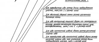
The table shows the purpose of the fillet weld leg
:
The fillet weld leg should not be higher than 1.2t, where t is the thickness of the thinnest element of the connection.
The estimated length of the fillet weld should not be less than 4kf (4 legs of the weld) and not less than 40 mm.
The overlap should not be less than 5 times the thickness of the thinnest element being welded.
The largest value of flank welds should not exceed 85βfkf, because the actual stress along the length of the weld will be uneven and some areas along the edges may experience overstress, and areas in the middle, on the contrary, will be understressed in comparison with the calculated value. This does not apply to those types of seams in which the force occurs throughout the entire length, for example, in the waist seams of beams.
Welding metal that is too thick and too thin is not recommended, as tension may cause the thin metal to bend.
What is written in the other tables
Next come tables 2 to 54. Each of them establishes the number of the welded joint, structural elements, part dimensions and their deviations. The number of items describing the sizes varies from 2 to 10 or more. Images of the prepared edges and weld are shown, all necessary symbols are indicated, including shading of the material.
Noteworthy is the table number 55. The thickness of the thin part and the difference in thickness of the parts are indicated here. According to GOST, depending on the size of the part, the difference should be in the range from 1 to 4 millimeters. A smooth transition is achieved using an inclined position of the seam surface. If the difference between the parts exceeds, on the one that has a large thickness, it is necessary to make a one-sided or double-sided bevel to the thickness of the thin part. The structural elements of the prepared edges and the dimensions of the seam after welding should be selected according to the smaller thickness.
After all the tables there are three appendices. The first describes the yield strength of the steel being welded in Megapascals and the fillet weld leg for a thicker element. In this case, the minimum value of the leg should not exceed the thickness of the thinner element by more than 1.2 times.
Appendices 2 and 3 describe in detail the fillet weld leg, including maximum deviations from the nominal value, the leg for the relationship between the tensile strengths of the weld metal and the base metal. Recommended values are indicated.
GOST, which describes welding parameters, welds and structural elements, is an important document. With its help, the production process is controlled, designs and parts are selected according to thickness. This book is a must for welders and similar professions, as its use guarantees high-quality and reliable welding.
Source: tokar.guru
Methods for calculating the length of the weld and other connection parameters
When calculating the length of the weld, it is first necessary to eliminate or minimize the parameter errors that affect the strength of the joint. First of all, it is an indicator of compression and tension of the metal. To determine this process you need a formula:
Where:
Yс
– coefficient showing workplace conditions. This indicator is considered generally accepted and can be found in the corresponding tables. It is necessary to substitute the desired indicator into the formula.
Rу
– metal resistance index, which takes into account its fluidity. It can be found in specialized reference books.
Ru
– the second indicator of metal resistance. It can be found in reference books.
N
– indicator of the maximum permissible load on the joint.
T
– the value of the thinnest wall thickness of the parts being welded.
Lw
— maximum length of the weld. When calculating, this parameter must be reduced by 2t.
Rwу
– resistance, which depends on the maximum strength of the connection.
When welding different metals, it is necessary to take the Ru and Ry indicators of the metal that will be less durable. Do the same when you need to calculate the length of the weld for shear.
When developing metal structures, the main thing is to take into account not only the requirements and safety standards of the welded joint, but also its permissible load level. If it is necessary to create several welded joints, it is important to distribute them correctly. The welding load must be distributed evenly between each joint.
The connection parameters are calculated using mathematical calculations. If the final result turns out to be unsatisfactory and unsuitable, then changes must be made to the design and then recalculated.
The permissible length of the weld seam for tearing is determined taking into account the force directed towards the center of gravity. A section with a high degree of danger is selected and calculations are made using this formula:
The type of metal in this case will not affect the strength of the seam, but each indicator presented in the formula will. In it:
N
– the maximum indicator of force exerting pressure on the joint.
ßf, ßz
– coefficients from reference tables, the value of which will not depend on the type of metals being welded. Typically, ßz = 1 and ßf = 0.7.
Rwf
– shear resistance value. This indicator is taken from reference books and GOST tables.
Rwz
– resistance indicator along the weld line. Values can be found in reference books.
Ywf
– correction factor, the indicator of which depends on the resistance of the metal. For example, if for metal the indicator is 4,200 kgf/cm², then the correction factor will be equal to 0.85.
WITH
– coefficient indicator of working environment conditions. The corresponding values can be found in the reference book.
Kf
– thickness of the joint along the fusion line.
Lw
– total joint length reduced by 10 mm.
In lap joints, the position in space and the type of welded joint are taken into account, since the joint itself can be either corner, flank, or frontal. The calculations made make it possible not only to obtain data on the minimum permissible welding area, but also indicators regarding the design strength of the joint lines.
To calculate the welding area, the height of the conditional triangular seam is taken as the base. In manual welding, this figure will be equal to 0.7, provided that the legs are equal. If the work is performed by automatic or semi-automatic devices, the degree of heating of the metal will be greater, and the coefficient will change accordingly. Indicators must be taken from reference tables.
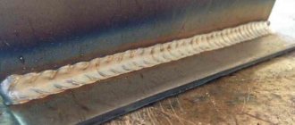
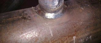
Reinforcement of butt seams
Strengthening butt welding is complicated by the fact that most often its strengthening can lead to damage to the joint. For example, if the butt seam is made along the entire length or height of the metal components, then no reinforcement can be done at all. Surfacing will create excessive concentration at the melting point, due to which the surfacing can not only deteriorate, but also completely collapse. The thing is that the height of such welds is determined only by the elements being joined and taking into account the structure of the bead of the connection itself. This roller is the protrusion.
If the butt welding still needs to be processed, then you first need to relieve the tension with abrasive tools. After this, the area of the overlays is calculated, with the help of which the seam will be strengthened.
Calculation of the length of the weld based on the mass of the metal
To calculate the length of the weld, there is a certain formula that correlates the mass of the deposit and the length of one meter of the weld.
The formula looks like this
:
L = G/F × Y, where:
L
– length of the joint,
G
– mass of the deposited metal,
F
– cross-sectional area,
Y
– indicator of the specific gravity of the additive.
The obtained values are multiplied by meters determined by measurements. For the correctness of the calculations, it is best to first look at an illustrative example in which the length of the weld is calculated.
It is important to remember that there is not a single formula that would provide a 100% accurate result. When purchasing material, always leave 5-7% as a reserve. Experienced welders can save on additives, but this requires the appropriate skill.
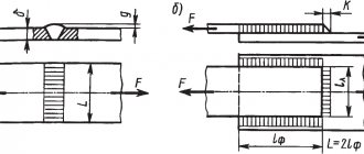
Calculation of weld leg length
Heavy objects to be welded, such as metal structures and cars, must withstand high loads, so for a quality connection it is extremely important to carry out accurate calculations that will take into account all parameters. One of them is the seam leg (K).
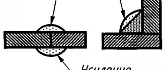
The weld leg is one of the sides of the largest conditional triangle with equal sides that can be inscribed in the cross-section of the joint (GOST R ISO 17659-2009, which came into force on July 1, 2010). This side can be measured based on the dimensions of the elements being welded.
When choosing a side, it is important to consider the size of the workpieces, their position and type of welding. The selection is carried out for each element, but is considered in general terms. It is acceptable to use a template for household measurements.
The connection will be strong if the same sides of the triangle have the same length. Relevant for elements located at an angle of 90°.
Types of connections
:
- butt (without beveled edges, with one-sided, with V-shaped, X-shaped, curved bevel);
- end;
- overlap;
- corner (angle from 30°, one-sided, two-sided without beveled edges, with one or two bevels);
- T-shaped (acute or straight angle, one-sided, two-sided, without beveled edges, with one or two bevels).
It is possible to calculate the length of the weld leg depending on the thickness of the material only for three types of welds: fillet, T-joint and overlap. Such calculations must be carried out when working in the industrial sector. The strength of the joint, wire consumption and its diameter depend on the indicator of these calculations.
be careful
! If the side of the triangle is long, due to the larger heating area, the volume of liquid metal and additive consumption will increase, which means that there is a possibility of product deformation.
When welding parts of different sizes, the leg length is also taken into account. All calculations are based on lower values.
The volume of deposited metal will be equal to the square of the leg. For example, with an increase in K by 1 mm and a welding seam length of 10 mm, wire consumption will increase by 20%. For overlapping materials with a thickness of up to 4 mm, K = 4. If this value is greater, then 40% of the thickness is taken and another 2 mm is added.
Corner welded joints are
:
- normal (without convexity or concavity) – K will be equal to the thickness of the metal;
- concave – K = 0.85;
- convex – K= s × cos45°, where s is the width of the junction, cos45° = 0.7071;
- special (the triangle is not isosceles).
When calculating the length of the weld leg, among other things, the welding method and the fluidity of the material being welded play an important role.
The obtained result must be checked against the requirements of GOST 11534-75 and GOST 5264-80 or reference materials.
At home, for proper welding, you need to install the side of the triangle, which will be 1–1.5 mm thicker than the thickness. You can also determine the indicator using the table.
Remember that K is always less than the thickness of the thinnest part multiplied by 1.2. The length of the weld must be no less than K times 4.
As a rule, all calculations are quite conditional, because in practice they are based on the following premises:
- the load is distributed evenly along the entire length of the deposited filler;
- destruction is possible only through an additive layer equal to 0.7 K.
In fact, the purpose of design calculations is to determine the most suitable weld dimensions for a given value of elongation and axial stress.
The optimal length of the deposited filler based on tensile load can be determined using the following simple formula:
L = F / ρ × [ρ], where:
L
– length of the junction;
F
– planned actual load on the connection;
ρ
– permissible load on the connection.
Optimal length for axial stress
:
L = F / 0.7K × ρ.
From this formula we can derive a formula for calculating K for a deposited filler length of 1 m:
K = 0.7 × L × ρ,
K=0.7 × ρ.
Thus, K will completely depend on the magnitude of the permissible load.
Permissible loads regarding compression, tension and shear for various welding methods can be found in specialized tables and reference books.
Important aspects when developing project documentation
:
- We decide on the choice of method, type of welding and brand of electrode.
- We find the permissible load norm.
- We calculate the length of the weld seam and the axial stress.
- We construct a drawing of the connection of materials.
- We specify the dimensions of the welded elements and technical indicators.
To improve the quality of welding and minimize unnecessary costs when preparing design documentation, it is necessary to determine the exact length of the weld leg from the material and the optimal length of the weld.
Recommended articles
- Types of welds: differences from joints and descriptions of varieties
- How to cook with electric welding: technology and important rules
- Capacitor welding: process features
The main thing is to get strong and high-quality connections at minimal cost.
This indicator plays a decisive role in the production sector of industrial enterprises that manufacture powerful metal structures. During operation, the latter must withstand heavy loads.
The length of the weld seam is one of the most important characteristics that determines the main parameters of the finished product. Any craftsman needs to know how to correctly calculate this indicator so that the work is done efficiently and reliably.
Cutting pipes for welding
GOST 16037-80 regulates not only the types of welded joints of steel pipelines (butt, lap and corner), but also the characteristics of preparatory measures taking into account the type.
Before carrying out welding work, it is necessary to carry out preparatory measures. These include:
- Mechanical cleaning of products . It is required to remove dust, traces of corrosion and oxide film.
- Chemical treatment to remove oil, grease and film stains.
- Edge cutting.
Cutting involves mechanical processing of the edge. During pipeline installation, cutting is carried out using special machines. When carrying out repairs, cutting using angle grinders is allowed.
Edge cutting must be performed when the thickness of the workpieces for welding is from 4 mm. For corner joints, bevel one or both edges at a 45-degree angle.
Joints on steel pipelines can be rotary or fixed. When welding a pipeline, it is recommended to use the first type, since they allow the welder to take the most advantageous lower position. The edges are cut along the entire perimeter.
With a butt connection, the difference between the wall thicknesses cannot be more than 10% and exceed 3 mm.
Before installation, the edges and heat-affected zone are also processed to 20-30 mm. It is cleaned of mechanical impurities, corrosion traces and oil and fat stains.
Before electric arc welding, the ends of the pipes must be tacked to each other. For pipe diameters not exceeding 300 mm, 4 tacks are made. If it exceeds 300 mm, then tacks are made evenly every 200-300 mm.
Welding of pipes with a thickness of more than 12 mm is carried out in three steps (penetrations).
If thick pipe blanks are connected, then the formed seam must be made thicker than the part itself. To form a connection with the specified parameters, you need to cut the edges after chamfering. At the same time, the electrode is provided with access for high-quality welding of the seam.
When calculating technological cutting parameters, special attention should be paid to the correctness of the calculation and compliance with certain cutting values. This reduces labor intensity, allows you to use materials economically and control costs.
When preparing joints, the type of chamfer depends on the thickness of the workpieces: with a thickness of 3-25 mm, a one-sided chamfer is used, with a thickness of 26-60 mm, a double-sided chamfer. For corner joints, the following boundaries are set: for values up to 20 mm - one-sided, up to 50 mm - two-sided.
Based on the geometric shape of the profile, the following subtypes of cutting are distinguished:
- Traditional (standard) bevel with a trapezoidal profile.
- X-shaped, when two bevels are made in such a way that the profile resembles the outline of the letter X (practice for using a workpiece with a thickness of 3-25mm).
- U-shaped, where the cross-sectional profile has a curved shape and resembles the letter U. GOST recommends using this form for large workpiece thicknesses (26-60mm) to reduce the cross-sectional area and reduce material costs.
If the pipe has a thickness of over 60 mm, then special shapes are used (in particular, ledges and complex curved profiles).
Gas cutters and mechanical processing are used for cutting. The first method has certain limitations and disadvantages: it has low qualities. The highest accuracy is ensured by milling; for large-diameter pipes, special trimming machines or grinders can be used.
Thus, GOSTs for welding activities are an important document that regulates the conditions for preparing and carrying out welding work. GOST 16037-80 defines methods for welding steel pipelines, types of connections, cutting methods and structural elements for each type. Compliance with the recommended parameters extends the service life of pipelines, ensures durability, strength and tightness of seams.