General technical characteristics:
- Pump displacement – 2.09 cm3
- Nominal pressure – 18 MPa
- Nominal flow – 3 l/min
- Oil tank volume – 20 l
- Drive motor power – 1.1 kW, 1500 rpm.
- Power supply – three-phase current, voltage 380 V, 50 Hz
- Weight (with dry tank) – 22 kg
- Dimensions – 450x370x410 mm
The configuration, physical dimensions, pressure and flow values can be changed at the request of the customer. All hydraulic pumping stations undergo mandatory inspection and testing
Will need
- Garden hose – 10-20 meters.
- Adapter from hose to 1/2 inch thread.
- Ball valve.
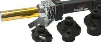
- Turbine, ordered from AliExpress – https://ali.pub/3v6u7f.
This hydraulic turbine generates voltage in the range of 12-22 V and produces power in the region of 10-20 W.
Purpose of the oil station
Hydraulic oil station with electric drive type NEE18-3I20T1 is designed to create hydraulic energy and use it in a bench installation to test the functioning of steering racks. The oil station is made in climatic version “U” of placement categories 2, 3 according to GOST 15150-69. Ambient temperature from plus 5°C to plus 40°C. Working fluid: VMGZ TU 38 101479-86, MGE-10A OST 38 01281-82. The cleanliness class of the working fluid must be at least class 10 according to GOST 17216-71. The temperature of the working fluid during operation of the pumping unit should be in the range from plus 5°C to plus 50°C. The operating position of the pumping unit is horizontal. Tilt up to 5° in any direction is allowed.
Description of the hydraulic circuit:
The electric motor (M) rotates the pump (H). The working fluid is sucked by the pump from the tank (B) through a mesh filter (F1), a high-pressure hose is supplied to the working cavity of the product. The maximum pressure of the oil station is adjusted using a safety valve (KV). The maximum operating pressure of the oil station is 18 MPa. The hydraulic distributor (P) is designed to control the flow of hydraulic fluid. The hydraulic valve spool positions are switched by an electromagnet from the control box (working position “A” and idling “B”). Return to the neutral position (“0”) is carried out due to the action of an elastic element (spring). The pressure in the system is controlled by a pressure gauge (MN) (0.40 MPa). An oil filter (F2) is installed on the drain line. The pressure difference of the working fluid before and after the filters should not exceed 0.5 MPa. A pressure drop above the permissible level leads to their failure. The working fluid is poured into the tank through a filler strainer (FZ). The liquid level in the tank and its temperature are respectively controlled using a level gauge (U).
Filtration system
To ensure continuous operation of the hydraulic station without breakdowns, it is necessary to keep the working fluid clean and remove foreign particles and debris from it that have entered during circulation through the system. Otherwise, moving parts may jam and various elements may wear out too quickly. This reduces the power of the station and leads to unreasonably high repair costs.
Complex hydraulic equipment with a large number of control elements requires multi-stage oil filtration. The choice of filter characteristics and installation locations depends on the parameters of the hydraulic system.
The following options are possible:
- For general-purpose hydraulic power stations and one-time-occasional operation, it is possible to install filters with a cleaning fineness of 80 microns;
- For hydraulic power stations with more intensive operating modes, 25 micron filters are installed;
- For equipment with automatic control systems based on proportional hydraulic valves, 10 micron filters are required.
Filter elements are installed in the suction, drain or pressure lines, or in a separate cleaning circulation circuit. They are mounted in such a way as to provide easy access for dismantling and replacing the filter element. It is recommended to use devices with a contamination indicator, which simplifies monitoring the technical condition of the degree of contamination.
In the diagram, the filters are numbered 3 (pressure), 4 (suction) and 5 (drain).
Oil station equipment
- 1) Tank
- 2) Cover
- 4) Gear pump
- 5) Electric motor
- 6) Coupling with elastic element
- 7) Glass
 Four-line three-position hydraulic valve with electromagnetic control
- 9) Hydroblock
- 11) Safety valve
- 13) Pressure gauge
- 14) Pressure gauge stand
- 15) Filler neck with strainer and breather
- 21) Suction filter
- 22) Drain filter
- 23) Oil level indicator combined with a thermometer
- 24) Cork
Force created by hydraulic cylinders of different diameters and extension time
| Hydraulic cylinder liner diameter (mm) | Extension time per 100 mm (sec) | Force (kg) |
| 30 | 1.4 | 1300 |
| 40 | 2.7 | 2300 |
| 50 | 4 | 3600 |
| 60 | 5.6 | 5200 |
| 70 | 7.5 | 7000 |
| 80 | 10 | 9200 |
| 90 | 13 | 1170 |
| 100 | 16 | 14400 |
Design and principle of operation of the oil station
The hydraulic oil station NEE18-3I20T1 consists of a tank 1 equipped with a cover 2; pump group, consisting of a pump 4 (gear), an electric motor 5, connecting their coupling shafts with an elastic element 6 and a glass 7, which acts as a shell, a four-line three-position hydraulic valve with electromagnetic control 8 mounted on a hydraulic unit 9, a safety valve 11, a pressure gauge 13 , installed on the rack 14, filler neck 15 with a strainer and breather; suction filters 21 and drain 22; oil level indicator combined with a thermometer 23. Oil from the tank is drained through plug 24. Oil from tank 1 is pumped by pump 4, driven by engine 5 through coupling 6, through suction filter 21 and pipeline and then enters hydraulic distributor 8, which supplies oil to pressure to the working parts. From the hydraulic distributor, oil flows to the drain through a pipeline to drain filter 22 and again enters tank 1. Oil is poured into tank 1 through filler neck 15. Oil is drained through plug 24 installed in the wall of tank 1. The oil level is monitored using indicator 23. The maximum pressure developed by the oil station is adjusted by safety valve 11. The pressure setting in the system is controlled by pressure gauge 13.
This is not a public offer. All information provided is for reference only. Specifications, specifications and physical dimensions are subject to change without notice.
My homemade mini oil station.
My homemade mini oil station.
I wonder who made a mini-oil station for themselves? What kind of engine, what connections, oil tank volume, regulators, valves, high pressure hoses, pump, hydraulic motor, hydraulic cylinders were used? Where was it used?
10 (or more) years ago Posts: 186
Re: My homemade mini-oil station.
Petrovich DD Writes: ——————————————————- > I wonder who made a > mini-oil station for themselves? What > engine, what > connections, volume > of the oil tank, regulators, valve > on, RVD, pump, hydraulic motor, guide > were rotary cylinders used? Where > was it used? It would not hurt to immediately clarify why this station is needed, otherwise not everything is on topic, but I want to understand.
10 (or more) years ago Posts: 1,510
Re: My homemade mini-oil station.
I made myself several different oil stations for homemade machines and presses. What is it for?
11 (or more) years ago Posts: 39
Re: My homemade mini-oil station.
For example, take as a basis an internal combustion engine of 13-14 hp, and on this basis build a mobile mini-hydraulic station for rotating a casing string diameter 159 mm, for drilling holes diameter 250-300 mm with a depth of 1-2 meters, can be used for jacking (for blasting casing or tool wedge), and the application, on a drill, it is interesting to find out how it is made and works.
10 (or more) years ago Posts: 186
Re: My homemade mini-oil station.
Yes, it’s not a problem to make a hydroelectric station at all. You just need torque to rotate the drill rods, and the hydraulic motor is good with a planetary gear and is oh so expensive. and for a jack you can only use a hydraulic cylinder, because for this you don’t need an internal combustion engine, a 3 kW electric motor is enough
11 (or more) years ago Posts: 39
Re: My homemade mini-oil station.
I looked in the hydraulics section. There are some good tips there. I’m wondering how I can build a mini-oil station myself
10 (or more) years ago Posts: 10
Re: My homemade mini-oil station.
It’s not a question of doing this, the question is what pressure and amount of oil per minute is needed. This is known. Well, then the oil pump has the required performance. and pressure, a distributor, it usually has a pressure reducing valve and a consumer. Drive power per pump. Let’s say NSh-10 3 kW, three-phase with a nominal capacity of 60 atm., well, consider if you need more displacement. What kind of engine will be needed?
11 (or more) years ago Posts: 2,913
Design and principle of operation of an oil station for a press
What is a hydraulic press
The Latin word pressus means “pressure” - and it has widely entered our lives precisely in its immediate meaning. And the “press” - printed matter produced by pressing a colored form onto paper, and the abdominals - a group of muscles that press on the internal organs, and the pressing machine - all these terms are the heritage of the ancient Romans.
In technology, a press is a device designed to apply pressure to any external object. If the force for this external pressure is generated by the pressure of the working fluid inside the device itself, the press is called hydraulic (another legacy of the ancestors, this time the ancient Greeks: “gidor” - water, “avlos” - tube).
1ou › Blog › Miniature hydraulic station (pump) - beginning
Good afternoon, Kulibins!
Hydraulics is the main “force” of modern mechanical engineering and is used everywhere: from the simplest technological equipment, metal-cutting machines, road construction equipment to aviation and astronautics. A hydraulic cylinder can be bought for 3-15 tr. for various applications: for a firewood splitter, for a small hydraulic press, for a hydraulic vice, for hydraulic body straightening devices, for a car lift, for a gate drive, and so on... I need this for a homemade hydraulic lift - www.drive2.ru/b/ 497889377578385827/ It all works according to the simplest laws of physics: P = F / S (Pascal’s Law); Accordingly, you need a hydraulic oil station, which combines an engine, a hydraulic pump, a tank with working fluid and hydraulic valves.
But miniature and cheap hydraulic (oil) stations are not produced from domestic components. The typical price in Russia for a low-power hydraulic station starts from
25 - 30 thousand rubles. You can order on Chinese websites and wait for an unknown Chinese craft that will go through the entire cycle of production, shipment, delivery, and customs only if you really need a whole batch of products and have experience working with Chinese sites like Alibaba. It’s easier with European products, but I have neither the money, nor the experience, nor the desire to order foreign products. This is what the finished mini station looks like:
Gear pumps are produced in Russia and the price tag for an NSh 10 type pump ranges from 800 to 1500 rubles. AIR electric motors are also produced and are affordable. Thus, all that remains is to make a project and connect it all into a single structure, resulting in a homemade miniature hydraulic station. Now I’m actively engaged in design, because without a project I’ve already scrapped a lot of metal and wasted a lot of time.
UPDATE 2022 - there is an addition to the entry regarding the type of engine and pump below
The assembly is planned to include: Electric motor AIR 100 S4 (flange), 3 kW - 7500 rub.
There is also a power steering check valve KK-1 UYAISH.306577.010 on sale - 1500 rubles, which should be suitable for the NSh10 pump
Making a hydraulic press with your own hands
The hydraulic press has become widespread. This device is used in many auto repair shops for pressing and unpressing bearings, various gears and shafts. In a home workshop, a manual hydraulic press, made by hand, is very often used, since installations made in industrial conditions have a high cost.
A self-made hydraulic press can be used in workshops to stamp parts made of metal, plastic and rubber. A hydraulic press can be used to press in rubber bushings on the ends of automobile shock absorbers in a home workshop.
If you have skills in working with equipment and access to milling, drilling and turning equipment for your home, you can design a hydraulic manual press (HH), which is capable of developing a maximum force of up to 35 tons per 50 sq. m. see. It’s not difficult to make a hydraulic tabletop press with your own hands, and you can save a significant amount of family budget money.
Comments
How many kilograms does such a pump produce?
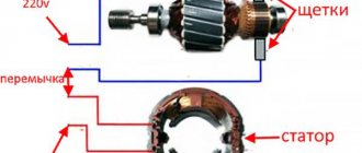
the starter has a maximum of 200 rpm and the pump has 2600 - I wonder HOW it works
Directly, the starter power is not enough, the pump will not produce full power
It is not clear what the alignment of the starter armature can be with a splined connection? if the anchor is on bushings.
You can pump water with this thing
relevant for converting a gazelle into a dump truck
Hello! What is the purpose of this system?
and on the tractor the pump has an adapter plate with bearings, won’t it break the NS?
Great idea ! Let's wait for the continuation!
Operating principle and design features of the device
You can construct a hydraulic press in a home workshop using available rolled metal. The main working element of any hydraulic press is a car hydraulic jack. Most often, the press uses a common design for a car jack - a bottle jack. Jacks of this type, depending on the design features, can lift from 2 to 100 tons. A huge advantage of a car hydraulic jack is the simplicity of its design and ease of use.
The operation of the jack is based on the basic laws of hydrodynamics, in particular Pascal's law, which states that the fluid pressure that occurs in a closed hydraulic system is transmitted equally in any direction. When combining 2 containers of different volumes into a single system and applying pressure in a smaller container, the same pressure applies to the liquid in the larger container, and the force that is applied in the small container of the system, transmitted to the liquid in the larger container, increases by so much the same time as the diameter of the smaller vessel differs from the larger one.
Depending on the technical purpose, the hydraulic press can be made in both table and floor versions. The tabletop version is more compact, while the floor-standing design requires additional space to accommodate. The production of one or another modification depends on the specific tasks for which the device is being manufactured.
Necessary tools
Each specific case may require its own set of tools and materials required for assembly. Their main set:
- welding machine;
- Bulgarian;
- drill;
- drill;
- taps for thread cutting;
- set of wrenches.
The list can be supplemented with items depending on the assembly conditions.
Required parts:
- hydraulic pump;
- hydraulic distributor;
- hydraulic tank;
- transmission belt;
- hoses and their fastenings;
- hydraulic cylinders;
- bolts and nuts;
- clamps;
- oil filter;
- various fasteners, the name of which is determined by each specific case.
The main components are shown in the photo.
How to make hydraulics for a mini-tractor with your own hands?
Hydraulics is a technical system that operates through the influence of fluid pressure on other elements of the system. During the impact process, kinetic energy is generated, which is converted into mechanical energy, as a result of which the useful work of a particular mechanism is performed. Various agricultural units, such as mini-tractors, are equipped with a hydraulic system. It is used to control various attachments.
This system is present in the design of any tractor produced by the manufacturer. It can be modified and optimized to suit your needs. A homemade mini-tractor must be equipped with hydraulics, which will allow you to use the equipment with maximum efficiency.
Classification
Extensive experience in the creation and operation of various hydraulic drives has shown that only limited types of pumps can develop high pressure. These include piston and plunger types. The hydraulic pump drive comes in three design types:
- manual (muscular);
- mechanical;
- pneumatic.
The use of hydraulic drives with ultra-high pressure (over 70 MPa) makes it possible to significantly reduce the dimensions and weight of equipment and increase its specific performance. The development of high-pressure systems is one of the key factors in the creation of compact, powerful hydraulic drives and mini-equipment for various sectors of the economy.
Design features
Hydraulics on a mini-tractor work on the same principle as all other similar systems. It contains a hydraulic pump that builds up pressure in the system and forces fluid to move through it. It is connected to a source of filler, which is an expansion tank. This unit is driven by transmitting torque from a diesel engine through a belt or mechanical connection to a shaft or transmission.
Although the system is called hydraulic, it is filled with oil. It has a lower boiling point, a suitable expansion coefficient and serves as a lubricant for the moving parts of the mechanism.
Flexible hoses with reinforced walls are used to transfer fluid through the system. All their connections are sealed and reinforced. Through them, under the influence of pressure, the oil enters the hydraulic distributor with a floating position, and then into the hydraulic cylinders, which act as pistons. The pistons perform mechanical work, which drives the corresponding attachments.
Some modifications of hydraulic mechanisms require integration into the wheel hydraulic drive system. This installation complements the tractor's braking system, which makes it easier to use the brakes, especially in homemade agricultural equipment. The hydraulic linkage can also be used to facilitate steering, acting in this case as a hydraulic booster. These design features of the mini-tractor’s hydraulic system allow you to control the operation of all mounted mechanisms, the vehicle’s own components, and effectively perform assigned tasks.
In order to assemble the hydraulics for a mini-tractor with your own hands, you will need the components of the mechanism produced at the factory using special equipment:
- hydraulic pump;
- hydraulic distributor;
- hose fastenings;
- hydraulic cylinder;
- other components that cannot be made at home.
The listed elements can be purchased in a store as a complete set or dismantled from old specialized equipment, while the rest of the fastening structure can be designed and assembled with your own hands.
Brief theoretical part
Hydrogen, also known as hydrogen, the first element of the periodic table, is the lightest gaseous substance with high chemical activity. During oxidation (that is, combustion), it releases a huge amount of heat, forming ordinary water. Let us characterize the properties of the element, formatting them in the form of theses:
- The combustion of hydrogen is an environmentally friendly process; no harmful substances are released.
- Due to chemical activity, the gas does not occur in free form on Earth. But its reserves in water are inexhaustible.
- The element is extracted in industrial production by a chemical method, for example, in the process of gasification (pyrolysis) of coal. Often a by-product.
- Another way to produce hydrogen gas is by electrolysis of water in the presence of catalysts - platinum and other expensive alloys.
- A simple mixture of hydrogen + oxygen gases explodes from the slightest spark, instantly releasing a large amount of energy.
For reference. Scientists who first separated the water molecule into hydrogen and oxygen called the mixture an explosive gas due to its tendency to explode. Subsequently, it received the name Brown's gas (after the name of the inventor) and began to be designated by the hypothetical formula NHO.
Previously, airship cylinders were filled with hydrogen, which often exploded
From the above, the following conclusion suggests itself: 2 hydrogen atoms easily combine with 1 oxygen atom, but they part very reluctantly. The chemical oxidation reaction proceeds with the direct release of thermal energy in accordance with the formula:
2H2 + O2 → 2H2O + Q (energy)
Here lies an important point that will be useful to us in further debriefing: hydrogen reacts spontaneously from combustion, and heat is released directly. To split a water molecule, energy will have to be expended:
2H2O → 2H2 + O2 – Q
This is the formula for an electrolytic reaction that characterizes the process of splitting water by supplying electricity. How to implement this in practice and make a hydrogen generator with your own hands, we will consider further.
How to do it?
Work on creating your own hydraulic system for a mini-tractor begins with designing a future design and carrying out calculations aimed at optimizing the ratio of expended resources and efficiency. The power of the tractor must correspond to its intended purpose, and the technical characteristics of the hydraulic system components are proportional to the loads applied to them.
Insufficient power of the oil pump or low load capacity on the hydraulic cylinders can lead to rapid failure of the entire system or individual components. An overestimated level of these indicators will increase the consumption of fuel and other resources and create an imbalance in the system. To compensate for the difference in technical characteristics and equalize the balance, additional items are installed: a second pump, a hydraulic cylinder, and others.
The drawing must reflect the design of the supporting frame, which will include space for the pump, distributor, pistons and other additional elements, as well as a hydraulic circuit connection diagram. At the same time, its configuration must be optimized in such a way that the distance from the engine output shaft to the nearest hydraulic system force transmission point is minimal.
The pump is installed as close as possible to the drive shaft. The reservoir with working oil is located above it, which ensures a free supply of liquid to the pump blades and reduces the leakage rate of useful mechanical energy. A filter is installed between the liquid reservoir and the pump. Its presence prolongs the uninterrupted operation of the entire system.
By means of reinforced hoses, the pump is connected to a hydraulic distributor, which is equipped with control elements. There may be several of them depending on the functionality of the hydraulics. Since in order to maintain pressure in the system, oil must continuously circulate through it, the distributor regulates the direction of its movement and supply to the cylinders, and also cuts off the flow during idle operation. The distributor controls are special levers supplied by the manufacturer with it.
After mounting the distributor, hydraulic cylinders are installed on the working part of the frame. These elements can be represented by special piston blocks designed for use in a hydraulic system. In other cases, they can be made independently from oil-type automobile shock absorbers.
Attachments are installed on the tractor in conjunction with hydraulic cylinders - moving parts of the system that transmit mechanical force to it. The design of fastening mechanisms is determined by the type of equipment, its actual configuration and the nature of the target work performed with its help.
The assembled hydraulic system must be equipped with technical components and insulation means that require their mandatory installation. Among them are:
- drain unit in the hydraulic tank;
- pressure relief valve in the tank;
- pressure meter;
- shut-off valve;
- draining the pump and hydraulic distributor;
- fine filter elements at the inlet to hydraulic cylinders;
- O-rings, washers, gaskets, nuts, clamps.
Before starting work, the entire system is configured.
The working diagram of hydraulic equipment for a mini-tractor is shown in the diagram:
Communities › Homemade Garage Hi-End › Blog › Hydroelectric station
As they say, “due to business needs,” a need arose in production for a hydraulic station from which various hydraulic tools could be powered: hydraulic cylinders, presses, sheet benders, hydraulic motors, etc.
In general, this project has been brewing for a very long time, the first parts for it were purchased two years ago, but since there was no urgent need for such a device, the project remained in a dormant state. However, its time has come... This is one of the few projects that we built without any preliminary drawings. As they say, in place and from scraps. To be honest, this is hell (although almost everyone I know works this way). On the one hand, it seems like progress is immediately visible, but you also have to redo it 100,500 times, because you don’t foresee one thing, then you forget another... But you can feel like an Artist.
The engine was 2.2 kW at 1400 rpm (AIR90L4). The use of NSh type pumps was immediately abandoned due to the unclear situation with their quality and the real chances of running into outright defects. Instead of the NSh, we used a Taiwanese pump RG P2 with a displacement of 4 cm3, delivering a pressure of 250 bar (which is 1.5 times more than that of the NSh). The pump was connected to the engine through an adapter bell and a coupling with a polyurethane insert, fortunately all this stuff is standard, easy to buy and does not require any manipulations like “cut a piece from one part and weld it to another,” as happens with NSh.
Under the engine, we welded a mighty frame from 80x40 channel bars, the remains of which were gathering dust lonelyly in the corner. Cutting sheets 2mm thick were used on the tank.
We assembled everything first on oven mitts. Firstly, it’s easier to redo everything when something goes wrong (and I had to redo it often). Secondly, this is a way to force yourself to paint the product before using it. Usually, when everything is already assembled, there is no desire to disassemble everything and paint it, so half of the devices in our workshop can serve as sets for a film about a post-apocalyptic future. And when assembling on tacks, everything will have to be disassembled for welding, and at the same time painted.
We figured out a panel for installing the hydraulic distributor. We only had a single-section one in stock, but in the future there are thoughts of putting a distributor into 3 sections in order to get 6 working circuits and be able to connect up to 3 consumers to one station (one day this will definitely be needed).
Next, we installed the main filter and found a place for the starter to the engine. At first, they thought of placing the ports for connecting hoses next to the distributor, but then it became clear that this was not a very good idea, and in the final version everything moved down to the wheels
We put the device on wheels and began to figure out how to connect the hoses. This is where all the shortcomings of the “artistic” approach came out. Hydraulic hoses are quite rigid, so it is not always possible to connect them as originally intended. After some torment and alterations of the hoses, everything was connected like this.
Literally it immediately became clear that this was not a very successful configuration, and the BRS was moved downstairs. Otherwise, almost a meter of hoses of the connected tool would be “eaten up” due to the fact that the connection point is too high above the ground. The configuration was revised, and the BRS moved downstairs.
Then everything was disassembled, scalded, sent for painting and we suffered for two whole days waiting. Finally it's time for the final assembly.
Instructions for controlling the hydraulics of a mini-tractor
The system is controlled using a lever(s) in conjunction with a hydraulic distributor. Its (their) main function is to change the positions of the distributor control valves, supply pressure to the desired section, and disconnect the fluid circulation circuit from the final units of the unit.
A simple hydraulic system has three control lever positions:
- neutral - oil circulates separately from the pistons;
- expansion of the piston - pressure forces it to take the most extended position;
- movement of the piston - the pressure is released, the vacuum created by the escaping liquid pulls it along with it, returning it to its original position.
At the moment the piston(s) move, the attachment performs the work intended for the purpose of its production.
Any hydraulic system is equipped with mechanisms for starting and stopping the hydraulic pump, fixing positions and emergency (manual) control.
Related Posts
Please advise a hydraulic station for synchronous operation of hydraulic cylinders.
- Author: Daniil Gordienko
- February 15, 2022 1 comment
A hydraulic station is needed for the synchronous operation of hydraulic cylinders. Please advise what and how to choose?
Why does the hydraulic station not produce the required pressure, what should I do?
- Author: Kirill Erlikh
- February 15, 2022 1 comment
The hydraulic unit does not produce pressure, what should I do?
Questionnaire for ordering a hydraulic station: what parameters do you need to know to order and manufacture a hydraulic station?
- Author: Sergey Mikhailov
- February 15, 2022 1 comment
What parameters must be specified to order a hydraulic station?
Hydraulic power stations for hydraulic tools: features and differences
- Author: Alexey Kramarenko
- February 15, 2022 2 comments
What is the peculiarity of hydraulic power stations for hydraulic tools, how do they differ from conventional hydraulic power stations?
DC hydraulic station 12/24V for hydraulic press
- Author: Yakov Damsky
- February 15, 2022 1 comment
Please tell me, is it possible to use a 12/24V hydraulic station to operate a hydraulic press?
Consultation with a hydraulic engineer
- Author: Denis Tolstosheev
- September 11, 2022 no comments
Good afternoon, please tell me how I can get advice on the topic of hydraulic components? I am interested in issues related to the diagnostics of the hydraulic system and, in general, the purchase of hydraulic pumps/hydraulic motors/hydraulic distributors, selection of analogues, etc. I don’t want to make a mistake in choosing, but I have very little experience, I don’t know what to pay attention to.
Oil for hydraulic power station: what kind of oil should be poured into the hydraulic power unit? Can I use a non-hydraulic one?
- Author: Vladimir Volosatov
- February 20, 2022 1 comment
What kind of oil should I pour into the hydraulic station?
What is hydraulic fluid?
- Author: Vyacheslav Makarov
- February 11, 2022 no comments
Hydraulic fluid is a kind of energy transfer mediator used in all hydraulic systems. However, the functionality of hydraulic fluid is not limited to simple energy transfer. Although transmitting hydraulic power is the primary purpose of hydraulic fluid, it also performs four auxiliary functions: heat transfer, contaminant removal, sealing, and lubrication.
Under normal conditions, hydraulic machines produce enormous amounts of excess heat, often caused by inefficiencies in the components themselves, such as pumps and motors. Without the ability to dissipate heat from these components, they can easily overheat, causing damage to valves and internal components, especially in low local viscosity environments. When the oil returns to the reservoir, it passes through a cooler many times, which keeps it at an optimal temperature until it is returned to the hydraulic system. Conversely, hydraulic fluid can be used to provide heat to the system during idle starts when needed.
We turned off the tractor, started it up the next day - neither the steering wheel nor the hydraulics worked. What could be the reason ? Amkador 342v
- Author: Arthur Petrosyan
- 01 July 23:49
Good evening, can anyone help? Advice or something else? I worked all day. They turned off the tractor the next day and started it up. The steering wheel doesn’t work. The hydraulics have all failed! What could be the reason ? Amkador 342v
Hydraulics. Why does the grab rise by itself?
- Author: Zulfir Tukhbetov
- March 27 15:38
Hello guys, please tell me the hydraulics lifts the grab by itself