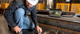
Objects intended for transportation or storage of liquid and gaseous substances must be subject to control of the tightness of welded joints. The tightness test is carried out by the company's quality control department. Periodic monitoring during operation is carried out by the owner within the time limits determined by regulatory documents.
Determination of seam tightness
"Important! The finished product is checked by the manufacturer during operation; this procedure is carried out by the owner within the specified time frame in the regulatory and technical documentation.”
There are several verification methods, each of which has a narrow focus. It is important to use the method that is most appropriate under specific conditions.
Control methods are selected depending on the operating conditions of the product:
- chemical properties of the working environment;
- physical parameters: pressure;
- temperature;
- operating time.
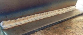
Checking the tightness of welded seams is intended for all critical products. The requirements for checking point and roller joints differ due to fundamental differences in technology, shape and purpose. Unlike all possible methods, kerosene testing of welds allows this study to be carried out at home.
- Roller welding is a type of spot welding, but due to the special shape of the electrodes, presented in the form of two rollers through which current passes, the seam is solid. The surfaces are connected by the method of overlapping each other, therefore this type of welding is characterized by such types of defects as: lack of penetration (in case of insufficient current strength, clamping pressure or current supply of insufficient duration in time),
- insufficient overlap of the joint,
- splashes of metal (external and internal). Determining the cause, as well as the exact location, is difficult due to the overlap method.
It is complicated by inaccessible observation of the seam under the overlap, in which defects, as well as the exact location, become difficult to determine.
- Spot welding is a type of seam in which the entire seam is made in the form of points overlapping one another. Can be performed using electric arc, point, or welding methods.
Application area
1.1. This standard applies to adsorption gas purifiers (hereinafter referred to as adsorbers) with a fixed bed, moving granular adsorbent, fluidized dust-like adsorbent of vertical or horizontal type and other devices similar in functionality [1].
Adsorbers are designed to absorb gases or vapors from gas mixtures with solid absorbers (adsorbents) [2].
This standard can be used for the certification of adsorbers.
The requirements of this standard are mandatory.
Hydraulic weld test
It is carried out using water, which is supplied under pressure 1.5-2 times higher than the working pressure of the vessel. Within 10-15 minutes, the tightness of the seams is checked: fogging, moisture, etc.
Pneumatic seam test
The most environmentally friendly way. A defect such as a weld fistula can form during operation, in places where critical stress occurs in the metal structure, or due to pitting corrosion, as well as with a poor-quality welded joint. Pneumatic or vacuum testing. A soap solution is applied to one side of the seam, and a vacuum chamber is attached to the opposite side. If there is a crack, air enters the chamber, and the location of the leak is determined by the bubbles. Disadvantages include low productivity and technical unprofitability when testing large containers.
Pneumatic seam test
Checking welds with kerosene
How to test a weld for leaks with kerosene? This substance was not chosen by chance: it has high fluidity, several times more than water. In addition, checking welds with kerosene allows you to identify microscopic cracks and fistulas at home, without complex devices. It is carried out as follows: a chalk film is applied to the surface being tested, which should serve as an indicator, and kerosene is poured onto the reverse side.
Checking the tightness with kerosene
Checking the seam with ammonia
This type of check is also based on indicator readings. It is carried out using compressed air to which an ammonia solution is added. On the opposite side, apply paper or a clean medical bandage. The indicator substance is phenolphthalein, which is used to impregnate the material or 5% mercury nitrate. When ammonia comes into contact with the indicator, a reaction occurs that produces a purple color.
Testing a welded joint with a leak detector
The most complex method of all existing ones, but its use allows not only to determine the location of the leak, but also to determine its size by calculation. Three substances can act as a working medium:
- halide gas (freon-12);
- carbon dioxide;
- carbon tetrachloride;
- helium.
- A leak detector installation is used with a platinum heated probe installed in it and a milliammeter recorder. It is carried out as follows: a test vessel immersed in a container is subjected to double pressure. The working gas is supplied inside, and from the outside, on the contrary, the gas is sucked into a special gas. receiver with platinum probe. When gas ions appear, a reaction occurs with the ions located on the probe, which is recorded by an ammeter.
- Therefore, the second method, with helium, is based on the same principle of operation. Only when entering a vacuum environment, helium ions hitting the ion collector create an electrical discharge. In both cases, the size of the crack is calculated using a milliammeter.
- In the case of testing with carbon dioxide, the calculation is carried out on the principle of changing the heat transfer between heated platinum wires up to 100 ºС and CO molecules entering the chamber. The sensitive wire increases the resistance, which leads to imbalance and deviation of the measuring device.
Normative references
This standard uses references to the following standards:
GOST 12.1.005-88 System of occupational safety standards. General sanitary and hygienic requirements for the air in the working area.
GOST 12.1.010-76 System of occupational safety standards. Explosion hazard. General requirements.
GOST 12.2.003-91 System of occupational safety standards. Production equipment. General safety requirements.
GOST 12.2.049-80 System of occupational safety standards. Production equipment. General ergonomic requirements.
GOST 12.4.011-89 System of occupational safety standards. Protective equipment for workers. General requirements and classification.
GOST 17.2.3.02-78 Nature conservation. Atmosphere. Rules for establishing permissible emissions of harmful substances from industrial enterprises.
GOST 17.2.4.06-90 Nature conservation. Atmosphere. Methods for determining the speed and flow rate of gas and dust flows emanating from stationary sources of pollution.
GOST 17.2.4.07-90 Nature conservation. Atmosphere. Methods for determining the pressure and temperature of gas and dust flows emanating from stationary sources of pollution.
GOST 17.2.4.08-90 Nature conservation. Atmosphere. Methods for determining the humidity of gas and dust flows emanating from stationary sources of pollution.
GOST 5264-80 Manual arc welding. Welded connections. Main types, structural elements and dimensions.
GOST 7512-82 Non-destructive testing. Welded connections. Radiographic method.
GOST 8713-79 Submerged arc welding. Welded connections. Main types, structural elements and dimensions.
GOST 11533-75 Automatic and semi-automatic submerged arc welding. Welded connections at acute and obtuse angles. Main types, structural elements and dimensions.
GOST 11534-75 Manual arc welding. Welded connections at acute and obtuse angles. Main types, structural elements and dimensions.
GOST 14249-89 Vessels and apparatus. Norms and methods of strength calculations.
GOST 14771-76 Arc welding in shielding gas. Welded connections. Main types, structural elements and dimensions.
GOST 14776-79 Arc welding. Spot welded connections. Main types, structural elements and dimensions.
GOST 14782-86 Non-destructive testing. Welded connections. Ultrasonic methods.
GOST 14806-80 Arc welding of aluminum and aluminum alloys in inert gases. Welded connections. Main types, structural elements and dimensions.
GOST 15164-78 Electroslag welding. Welded connections. Main types, structural elements and dimensions.
GOST 15878-79 Contact welding. Welded connections. Structural elements and dimensions.
GOST 16037-80 Welded connections for steel pipelines. Main types, structural elements and dimensions.
GOST 16038-80 Arc welding. Welded connections for pipelines made of copper and copper-nickel alloy. Main types, structural elements and dimensions.
GOST 23518-79 Arc welding in shielding gases. Welded connections at acute and obtuse angles. Main types, structural elements and dimensions.
GOST 27580-88 Arc welding of aluminum and aluminum alloys in inert gases. Welded connections at acute and obtuse angles. Main types, structural elements and dimensions.
Definitions
In this standard, the following terms with corresponding definitions apply:
3.1. adsorption:
Absorption of gases or vapors from gas mixtures by a solid absorbent (adsorbent).
3.2. adsorber:
An apparatus for absorbing gases or vapors from gas mixtures with solid absorbers.
3.3. adsorbent:
Solid absorbent for trapping vapors or gases.
3.4. adsorber with fixed adsorbent:
A device in which the adsorbent layer does not change its position during the technological process.
3.5. adsorber with a moving layer of adsorbent:
An adsorbent in which a layer of adsorbent moves through the apparatus from top to bottom.
3.6. fluidized bed adsorber:
An adsorber in which adsorbent particles move intensively in a flow in various directions.
3.7. desorption:
Thermal regeneration of spent adsorbent, accompanied by the release of absorbed harmful substances.
Ultrasonic flaw detection
Ultrasound is used to control welding quality.
The operating principle of the device is based on the reflection of ultrasonic waves from the boundary between two media with different acoustic properties. The sensor and emitter are tightly applied to the material being tested, after which the device produces ultrasound. It passes through the entire metal and is reflected from the back wall, returning to the receiving sensor, which in turn converts ultrasound into electrical vibrations. The device presents the received signal in the form of an image of reflected waves.
If there are any flaws inside the metal, the sensor will record a distortion of the reflected wave. It has been experimentally established that various welding defects manifest themselves differently on an ultrasonic flaw detector. This made it possible to classify them. With appropriate training, a specialist can accurately determine the type of defect in a seam.
The method of ultrasonic quality control of welded joints has become widespread due to its simplicity and ease of use, relatively inexpensive equipment, and safety of use compared to the radiation method.
The disadvantage of this method is the difficulty of deciphering the graphic image. Connection quality control can only be done by a certified specialist. It is problematic to use it for testing coarse-grained metals such as cast iron.
Radiation
Radiation flaw detection is similar in principle to X-ray examination. Gamma rays released during a nuclear reaction have a high penetrating ability. Passing through the material, the radiation hits the photographic plate. After its development under a microscope, you can examine the distribution of the defect in the metal.
The interesting question about the harmfulness of gamma radiation remains relevant. Despite the protective measures provided, the human body receives an increased amount of radiation. If we add the high cost of equipment, it becomes clear that this method is not a priority.
Finding welding defects using ultrasound
The operating principle of flaw detectors is based on the fact that in a homogeneous medium, an ultrasonic wave moves in one direction. If any obstacles arise, the wave begins to be reflected.
The main flaw detection methods include:
- echolocation;
- shadow method;
- mirror method;
- mirror-shadow;
- delta method.
Safety requirements
4.1. General safety requirements according to GOST 12.2.003.
4.2. Each adsorber, used independently or as part of a technological complex, is equipped with operational documentation (ED) containing requirements (rules) to prevent the occurrence of dangerous situations during installation (dismantling), commissioning and operation.
4.3. The adsorber must meet safety requirements throughout the entire period of operation provided that the consumer fulfills the requirements established in the ED.
4.4. The design of adsorbers must exclude, in all operating modes, loads on parts and assembly units that can cause destruction that poses a danger to workers.
If loads may arise that lead to dangerous destruction of individual parts or assembly units for workers, the adsorber must be equipped with devices that prevent the occurrence of destructive loads, and the parts and assembly units must be fenced or located so that their collapsing parts do not create traumatic situations.
4.5. The design of the adsorber and its individual parts must exclude the possibility of them falling, overturning and spontaneous displacement during operation and installation (dismantling). If, due to the shape of the adsorber, the mass distribution of its individual parts and (or) installation (dismantling) conditions, the required stability cannot be achieved, then means and methods of fastening must be provided that meet the requirements contained in the ED for a specific adsorber.
4.6. Structural elements of adsorbers should not have sharp corners, edges, burrs or surfaces with unevenness that pose a risk of injury to workers.
4.7. Parts of the adsorber (including pipelines of hydraulic, steam, pneumatic systems, safety valves, cables, etc.), the mechanical damage of which may cause danger, must be protected by guards or located so as to prevent their accidental damage by operating or maintenance equipment .
4.8. The design of the adsorber must prevent spontaneous loosening or disconnection of fastenings of assembly units and parts.
4.9. The adsorber must be fire- and explosion-proof under operating conditions.
4.10. The design of the adsorber must be made in such a way as to exclude the accumulation of static electricity charges in quantities that pose a danger to the worker, and the possibility of fire and explosion.
4.11. The adsorber should not be a source of noise and vibration. The design of the adsorber must be made so that the concentration of harmful substances in the working area, as well as their emissions into the natural environment during operation, do not exceed the permissible values established by GOST 12.1.005 and GOST 17.2.3.02.
4.12. An adsorber designed to work with an explosive gas environment must meet the requirements of GOST 12.1.010 and be equipped with devices that remove a directed blast wave.
Adsorber seals designed to work with fire and explosive substances must prevent the formation of flammable and explosive mixtures in the operating and non-operating state of the adsorber.
4.13. The design of the adsorber must exclude the possibility of contact with hot parts or being in close proximity to such parts, if this could lead to injury or overheating of the worker.
The temperature of the outer surface of the shell with thermal insulation in service areas should be no more than 45 ° C.
The thermal insulation of the adsorber must be made of mineral or organic heat-insulating materials. The thermal insulation layer, if necessary, must be protected by a waterproof shell.
If the purpose of the adsorber and the conditions of its operation (for example, use outside industrial premises) cannot completely exclude contact of a person working with the hot parts of the adsorber, then the ED must contain a requirement for the use of personal protective equipment.
4.14. The design of the workplace, its dimensions and the relative arrangement of elements (controls, information display devices, auxiliary equipment, etc.) must ensure safety when using the adsorber for its intended purpose, maintenance, repair and cleaning, taking into account the substances used in the technological process, as well as meet ergonomic requirements according to GOST 12.2.049.
The need for fire extinguishing means and means used in emergency situations at workplaces should be established in standards and regulatory documents for adsorbers of specific groups, types, models (brands).
If the location of the workplace makes it necessary to move and (or) stay the worker above the floor level, then the design of the adsorber should include platforms, stairs, railings, other devices, the size and design of which should exclude the possibility of workers falling and ensure convenient and safe performance of labor operations, including maintenance operations.
4.15. The design of adsorbers must ensure the safety of workers during installation (dismantling), commissioning and operation, both in the case of autonomous use and as part of technological complexes, subject to the requirements (conditions, rules) provided for in the ED.
4.16. Adsorbers must be equipped with signaling and blocking devices that are triggered when the established technological operating mode is violated.
4.17. Service personnel who have studied their design and maintenance techniques are allowed to service adsorbers.
4.18. The design of adsorbers must be designed for the maximum operating (excess) pressure or vacuum that may arise during their operation.
Method – kerosene test
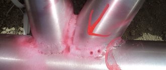
The kerosene test method involves moistening the part with kerosene, after which it is wiped dry and covered with chalk. After a few minutes, the chalk darkens in places where there are cracks. This method is difficult to detect cracks less than 0.05 mm wide. [1]
Less critical objects are controlled using the kerosene test method. On one side, kerosene (penetrant) is applied to the surface of the partition, and on the other, a developing coating in the form of a solution of chalk in water is applied. Exposure ranges from 40 to 120 minutes, depending on the thickness of the partition and its location. Leak locations are determined by the appearance of dark kerosene stains on the chalk surface. [2]
During installation work, the kerosene test method is often used, based on the high penetration ability of kerosene into defects. [3]
After eliminating the defects, the body is checked using the kerosene test. [5]
To identify defects (leaks), using the kerosene test method, one side of the welded joint is painted with chalk diluted in water. After the chalk has dried, the second side of the weld is generously moistened with kerosene. Kerosene, penetrating through defects in the weld, leaves greasy dark spots on the chalk paint, characterizing the presence and location of defects. Detected defects are eliminated and brewed again. Welds must be kept under kerosene for 12 hours or more. [6]
To identify defects (leaks), using the kerosene test method, one side of the welded joint is painted with chalk diluted in water. After the chalk has dried, the second side of the weld is generously moistened with kerosene. Kerosene, penetrating through defects in the weld, leaves greasy dark spots on the chalk paint, characterizing the presence and location of defects. Defects found are cut out and brewed again. Welds must be kept under kerosene for 12 hours or more. [7]
To check the practical results of heat treatment, they use the kerosene test method, which consists of immersing products at room temperature in kerosene for a certain time, or moistening individual places with kerosene. This method determines the presence or absence of internal stresses that cause cracks to appear during testing. [9]
To identify defects (leaks), using the kerosene test method, one side of the welded joint is painted with chalk diluted in water. After the chalk has dried, the second side of the weld is generously moistened with kerosene. Kerosene, penetrating through defects in the weld, leaves greasy dark spots on the chalk paint, characterizing the presence and location of defects. Defects found are cut out and brewed again. Welds must be kept under kerosene of 12 g or more. [10]
To identify defects (leaks), using the kerosene test method, one side of the welded joint is painted with chalk diluted in water. After the chalk has dried, the second side of the weld is generously moistened with kerosene. Kerosene, penetrating through defects in the weld, leaves greasy dark spots on the chalk paint, characterizing the presence and location of defects. Detected defects are eliminated and brewed again. Welds must be kept under kerosene for 12 hours or more. [eleven]
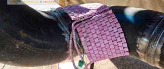
The tightness of the welded joints of the body and neck can be checked using the kerosene test method, for which the welded seams are coated on the outside with fine chalk powder diluted in water. When the whitewash has dried, the seams on the inside of the body are coated with kerosene. [13]
To detect surface defects (cracks), you can use the kerosene test method or the color method. The kerosene test method consists of immersing the part in a bath of kerosene for 20 - 30 minutes, and then thoroughly wiping it and covering it with a thin layer of chalk coating. The chalk coating absorbs the kerosene remaining in the cracks and darkens, revealing the cracks. [14]
Source: www.ngpedia.ru
Capillary control method
Capillary inspection methods are based on capillary penetration of liquids (penetrants) into defects and their contrast image. These methods are used to detect surface defects, mainly in products made of non-metals and alloys, for which it is impossible to use magnetic testing methods.
Stages of capillary control
Penetrant control is carried out as follows. After preparing (cleaning, degreasing) the surface of the part being tested, an indicator liquid is applied to it. The liquid penetrates into the defects. After application, the liquid is removed from the surface (wiped off or blown off), but it remains in the defects. Next, a developer is applied to the surface. The developer dries and the indicator liquid is absorbed into it from the defects, coloring the defect areas. The developer can be in powder form (dry method). You can apply solutions of phosphors (in a volatile solvent) as a developer - then the defect will glow in ultraviolet rays (powderless method). Defects are identified by external inspection using a magnifying glass; If phosphors were used, photosensors can be used. Capillary inspection reveals defects with a width of 1 µm, a depth of 10 µm and a length of 0.1 mm.
Verification methods
Testing of welds for tightness is carried out in the following ways:
- kerosene;
- ammonia;
- pneumatic;
- hydraulic;
- vacuum.
Kerosene
The method is used to check the density of welded seams of vessels and tanks made of metal up to 10 mm thick, not operating under pressure.
The kerosene test is based on the phenomenon of capillarity. The essence of the method is the ability of kerosene to rise through through pores and cracks. Kerosene testing allows you to identify defects with a size of 0.1 mm.
The technology consists of coating the seam on one side with a solution of chalk or kaolin in water. After the chalk composition has dried, the seam on the reverse side is moistened several times with kerosene. If there are cracks, pores, or discontinuities, kerosene seeps through them and appears as spots on the chalk paint.
Kerosene test time:
- at temperatures above 0 °C - from 4 hours , critical products - 12 hours;
- at negative temperatures - from 8 hours , for serious objects - 24 hours.
Ammonia
The method is based on the property of a certain type of indicator (mercury nitrate solution or phenolphthalein) to change color as a result of exposure to liquefied ammonia. Used for testing closed welded vessels for density.
The process technique consists of covering the outside of the weld with strips of paper soaked in a 5% solution of silver nitrate. Compressed air containing 1% ammonia is pumped into the control vessel. Ammonia vapor passes through seam leaks and reacts with mercury nitrate, causing the paper to turn silver-black opposite the location of the defect. If phenolphthalein solution is used as an indicator, the color of the paper will be bright red.
The nature and size of the defect depend on the speed at which marks appear on the paper, their size and shape.
The penetration time of ammonia through weld leaks ranges from 10 minutes to half an hour.
Pneumatically
The method is intended for checking the tightness of the welded seam of products working under pressure. Compressed air is pumped into a small closed vessel, sealed with a plug, to a pressure 10-20% higher than the working one. The product is immersed in water. The presence of weld defects is determined by air bubbles escaping through the leaks.
Large items are sealed and the seams are coated with soapy water. Gas is supplied to the structure under test at a pressure exceeding the operating pressure by 10-20%. A sign of a defect is the appearance of bubbles on a seam moistened with a soap solution.
Large vessels and gas pipelines are checked for pressure drop. Due to their large length, the seams are not washed. The presence of defects is determined by the pressure drop over a period of 24 hours.
Pressure testing does not allow tapping of welds. The test is carried out in an isolated room. Carrying out inspections of large-sized products requires caution.
Hydraulic
Depending on the type of structure, there are 3 types of hydraulic tests:
- hydraulic pressure (hydraulic systems, pipelines);
- filling water (tanks, tanks, reservoirs);
- watering with a stream of water from one side (long products).
- Hydraulic pressure method . The object being tested is sealed and filled under pressure with working fluid or water. The type of liquid, its pressure and test time depend on the purpose of the control sample. The trial test pressure figure is indicated in the project. For pipelines it is 1.25 or more working pressure values. Test control is carried out at air temperatures above zero. The result is considered satisfactory if there is no fogging on the weld and no leakage is detected, and the gauge pressure has not dropped.
- Bulk control . The product is filled with water to a specified level. At air temperatures above 0° C, water temperatures above 5° C, holding time – up to 24 hours. Constant monitoring of the drop in water level and the condition of the welds is required. When defects are detected, the seam located on top is freed from water, the defects are eliminated, and water is added to test the newly welded section of the seam. The operations are repeated until all defects are completely eliminated.
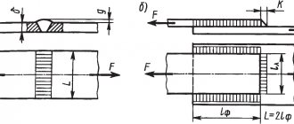
- Watering with a stream of water . The test is carried out with a stream of water from a fire nozzle with an outlet opening of 15 mm. The speed of the jet directed along the seam is 1 m/min. The water pressure in the hose is at least 1 atm. The distance from the tip of the fire nozzle to the surface of the product is up to 2 m. The surface of the side of the test sample, opposite the one being watered, must be dry. Its inspection is carried out simultaneously with watering. Defective areas are manifested by the occurrence of leaks, the appearance of water drops, and fogging of the surface of the weld or heat-affected zone.
Vacuum
The method consists of isolating the test product from the external atmosphere by pumping out air and checking the vacuum. If there are defects in the welds, the vacuum will be broken.
The method is suitable for monitoring the tightness of seams that are accessible only from one side - the bottoms of vertical tanks, gas tanks, waterproofing boxes, and the roofs of cylindrical oil tanks. The check is carried out using a vacuum device.
The camera of the device is installed on the joint of the seam, coated with an indicator - a soap solution - and the pump is turned on. Under the influence of atmospheric pressure, air passes through the leaks of the welded joint, and soap bubbles appear at the defects, which can be observed through the glass of the chamber. At low temperatures, sodium chloride (table salt) or calcium chloride is added to the foam indicator.
Source: elsvarkin.ru
Leak detection methods
Leak detection methods are used to detect through defects. For many products (vessels, closed volumes), the most important operational requirement is tightness, i.e. the property of a product to provide such a small penetration of gas or liquid that it can be neglected under operating conditions. Particularly high requirements are placed on products operating in a vacuum; such products must have a vacuum density. Through defects can also affect other characteristics of the connection (strength, corrosion resistance, electrical conductivity, etc.), therefore the leak detection method is applicable for other products, even for welded sheets.
Types of leak detection control
Leak detection methods are divided into:
- hydraulic;
- pneumatic;
- vacuum;
- chemical leak detection;
- kerosene and penetrants;
- gas analysis, etc.
Hydraulic leak detection method
Hydraulic methods use a liquid, usually water, as a penetrant, which is applied under pressure from one side of the seam. The defect is detected by the appearance of liquid on the opposite side of the seam. Various hydraulic control options are available. When testing with excess hydraulic pressure, water is supplied to the product under a pressure of 1.5. 2 times higher than working. The product is kept for a certain time, monitoring the pressure on the pressure gauge, then tapped with a hammer, leaks are detected in the form of streams and sweating on the surface of the controlled product. This method detects defects with a diameter of up to 0.001 mm.
Pneumatic leak detection method
Pneumatic tests are carried out with an air pressure equal to 1.1.2 working pressure. A type of pneumatic testing is the pressure gauge method, in which the product is kept under pressure from 10 to 100 hours. The change in pressure observed on the pressure gauge should not exceed the permissible value. High pressure testing is dangerous and is therefore rarely performed. It is possible to determine the location of a leak when testing with low pressure (0.03 - 0.3 MPa). For indication use soap suds or foam indicators based on detergents. Pores with a diameter of 10-3. 10-4 mm can be detected by blowing the surface of the weld with air from a hose at a pressure of approximately 0.4 MPa.
Vacuum leak detection method
Vacuum methods are based on the pressure difference created by pumping air out of the product. These include the manometric method, the electric spark method, etc. The soap indication method is widely used: a transparent chamber with suction cups is placed on the area of the seam being inspected, previously lubricated with a soap solution, in which a low vacuum is created. If there are defects in the seam, air penetrates through the discontinuities and soap bubbles form on the surface of the seam, visible through the transparent glass of the chamber. The method can be used to control butt and lap joints.
Chemical indication method
The method of chemical leak detection involves applying an indicator mass, paste or tape to the controlled joints of the vessel. A test gas is supplied into the vessel under excess pressure. The test gas penetrates through the leaks and colors the indicator. Ammonia or carbon dioxide is used as a test gas, and a 5% solution of mercury nitrate (if there is a leak, black or purple spots appear) or phenolphthalein (colorless spots appear on a crimson background) are used as an indicator.
Kerosene control method (chalk kerosene)
The kerosene (gasoline or alcohol) control method is based on the high penetrating ability of kerosene or other penetrant, such as gasoline or alcohol. Typically, the controlled seam is coated with chalk paint on the side accessible for inspection and elimination of defects. Then the seam is moistened with kerosene on the other side and kept for the required time (usually 15.60 minutes). Defects are identified by rusty stripes and spots on the chalk layer.
Legislative framework of the Russian Federation
Free legal aid hotline
- Encyclopedia of mortgages
- Codes
- Laws
- Document forms
- Free consultation
- Legal encyclopedia
- News
- about the project
Free consultation
Navigation
Federal legislation
- Constitution
- Codes
- Laws
Actions
- home
- “RULES FOR THE CONSTRUCTION OF VERTICAL CYLINDRICAL STEEL TANKS FOR OIL AND PETROLEUM PRODUCTS. PB 03-381-00" (approved by Resolution of the State Mining and Technical Supervision of the Russian Federation dated September 27, 2000 N 55) (as amended on November 21, 2002)
7.4. Leak control
7.4.1. All welds that ensure the tightness of the tank, as well as the buoyancy and tightness of the pontoon or floating roof are subject to leak testing.
7.4.2. Testing the tightness of welds using the chalk-kerosene test should be done by abundantly wetting the seams with kerosene. No stains should appear on the opposite side of the weld, previously coated with an aqueous suspension of chalk or kaolin. The duration of testing by the capillary method depends on the thickness of the metal, the type of weld and the test temperature. A conclusion about the presence of through defects in a welded joint is made no earlier than 1 hour after applying an indicator of through and surface defects to the seam.
7.4.3. When using a vacuum method for monitoring the tightness of welds, vacuum chambers must create a vacuum above the controlled area with a pressure drop of at least 250 mm water column. The pressure drop should be checked with a vacuum gauge. Weld seam leakage is detected by the formation of bubbles in a soap or other foaming solution applied to the weld joint.
7.4.4. It is allowed not to check the tightness of butt joints in wall sheets with a thickness of 12 mm or more.
7.4.5. Pressure testing is used to check the tightness of welds when welding reinforcing sheet linings of hatches and pipes on the walls of tanks. Control is carried out by creating excess air pressure from 400 to 4000 mm water column. in the gap between the tank wall and the reinforcing pad using a control hole in the reinforcing pad for this purpose. In this case, a soap film, a film of linseed oil or another foaming substance must be applied to the welds, both inside and outside the tank, to detect leaks. After testing, the inspection hole must be filled with a corrosion inhibitor.
7.4.6. It is recommended to monitor the tightness of welded joints on tank roof decks during hydraulic and pneumatic tests by creating excess air pressure inside the tank up to 150-200 mm water column.