Thyristor power regulators are used both in everyday life (in analog soldering stations, electric heating devices, etc.) and in production (for example, to start powerful power plants). In household appliances, as a rule, single-phase regulators are installed; in industrial installations, three-phase ones are more often used.
These devices are electronic circuits that operate on the principle of phase control to control the power in the load (more on this method will be discussed below).
Purpose and principle of operation
Using voltage regulators, you can change not only the brightness of incandescent lamps, but also the rotation speed of electric motors, the temperature of the soldering iron tip,
and so on. These devices are often called power regulators, which is not entirely correct. Devices designed to regulate power are based on PWM (pulse width modulation) circuits.
This allows you to obtain different pulse repetition rates at the output, the amplitude of which remains unchanged. However, if a voltmeter is connected in parallel to the load in such a circuit, the voltage will also change. The fact is that the device simply does not have time to accurately measure the amplitude of the pulses.
It should be noted that voltage regulators will be most effective when working with resistive loads, such as incandescent lamps. But using them to connect to an inductive load is impractical. The fact is that the inductive current is much lower compared to resistive current.
Assembling a homemade dimmer is quite simple. This will require some basic knowledge of electronics and a few parts.
Based on triac
Such a device operates on the principle of phase shift of key opening. Below is the simplest triac-based dimmer circuit:
Structurally, the device can be divided into two blocks:
- A power switch, in the role of which a triac is used.
- Unit for creating control pulses based on a symmetrical dinistor.
A voltage divider is created using resistors R1-R2
It should be noted that resistance R1 is variable. This allows you to change the voltage in line R2-C1
A DB3 dinistor is connected between these elements. As soon as the voltage indicator on capacitor C1 reaches the opening threshold of the dinistor, a control pulse is applied to the switch (triac VS1).
Thyristor based
These partings are also quite effective, and their patterns are not very complicated. The role of the key in such a device is performed by a thyristor. If you carefully study the circuit diagram of the device, you will immediately notice the main difference between this circuit and the previous one - for each half-wave, its own switch with a control dinistor is used.
The operating principle of the thyristor device is as follows:
- When a positive half-wave passes through line R5-R4-R3, capacitor C1 is charged.
- After reaching the switching threshold of dinistor V3, it is triggered, and electric current flows to switch V1.
- When a negative half-wave passes, a similar situation is observed for the line R1-R2-R5, the control dinistor V4 and the key V2.
Capacitor regulators are also used in everyday life. However, unlike semiconductor devices, they do not allow smooth voltage changes. Thus, thyristor and triac circuits are best suited
.
Finding all the parts needed to make the regulator is not difficult. However, you don’t have to buy them, but can be removed from an old TV or other radio equipment. If desired, you can make a printed circuit board based on the selected circuit, and then solder all the elements into it. The parts can also be connected using regular wires. The home master can choose the method that seems most attractive to him.
Both devices discussed are quite easy to assemble, and you don’t need to have serious knowledge in the field of electronics to complete all the work. Even a novice radio amateur can make a 220V voltage regulator circuit with his own hands. At a low cost, they are practically in no way inferior to their factory counterparts.
How it works?
The information described below is valid for most schemes. Letter designations will be taken in accordance with the first circuit of the thyristor regulator
A thyristor power regulator, the operating principle of which is based on phase control of the voltage value, also changes the power. This principle lies in the fact that under normal conditions the load is affected by the alternating voltage of the household network, changing according to a sinusoidal law. Above, when describing the operating principle of a thyristor, it was said that each thyristor operates in one direction, that is, it controls its own half-wave from a sine wave. What does it mean?
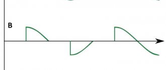
If you periodically connect a load using a thyristor at a strictly defined moment, the value of the effective voltage will be lower, since part of the voltage (the effective value that “falls” on the load) will be less than the mains voltage. This phenomenon is illustrated in the graph.
The shaded area is the area of stress that is under load. The letter “a” on the horizontal axis indicates the opening moment of the thyristor. When the positive half-wave ends and the period with the negative half-wave begins, one of the thyristors closes, and at the same moment the second thyristor opens.
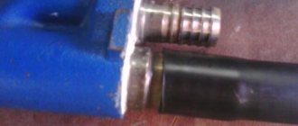
Replacing a triac in a dimmer
Hollow rivets can be removed using a 90° drill bit or side cutters. But in order not to damage the radiator, this must be done from the side where the triac is located.
The radiators, made of very soft aluminum, were slightly deformed when riveted. Therefore, I had to sand the contact surfaces with sandpaper.
- Screw M2.5x8.
- Spring washer (grower) M2.5.
- Washer M2.5 – fiberglass.
- Triac case.
- Gasket – fluoroplastic 0.1mm.
- Nut M2.5.
- Washer M2.5.
- Tube (cambric) Ø2.5x1.5mm.
- Washer M2.5.
- Radiator.
Since I used a triac that does not have galvanic isolation between the electrodes and the contact pad, I used the old proven isolation method. The drawing shows how it is implemented.
And these are the same parts of the galvanic isolation of the triac in its natural form.
To prevent the radiator wall from pressing through at the location where the triac is attached, a washer was placed under the screw head. And most of the head of the screw itself was ground off so that it would not cling to the handle of the potentiometer and power regulator.
This is what a triac isolated from the radiator looks like. To improve heat dissipation, thermal conductive paste KPT-8 was used.
What's under the dimmer housing?
Back in action.
Assembling the device
We will not describe all standard assembly actions; we will only note the main points. The transistor must be placed on a heat sink. Why? Because the circuit is linear and at high currents the transistor will get very hot. What is the radiator made of? It can be made from a regular aluminum corner and attached directly to the power supply fan. And, despite the fact that the radiator is quite small in size, thanks to the intense airflow it will cope with its task perfectly.
A transistor is screwed to the radiator through thermal paste; in this circuit it uses a field-effect, N-channel IRFZ44 with a maximum current of 49 A. Since the radiator is isolated from the main board and case, the transistor is screwed directly without insulating spacers.
The stabilizer board is fixed to the same aluminum corner through a brass stand. To regulate the output current, a 5 kOhm variable resistor is used. The wires are secured with plastic ties to prevent them from dangling.
As a result, you should get the following connection diagram for this stabilizer for the charger.
The power supply can be absolutely anything, either a computer power supply or a regular transformer. The cord used to connect to the outlet is a regular computer one.
All is ready. You can now use such an adjustable voltage stabilizer for the charger. It should be noted that the circuit is simple and inexpensive: it simultaneously functions as a stabilizer and a charger.
Thyristor circuits
You can regulate the total power of the soldering iron quite simply if you use analog or digital soldering stations for this. The latter are quite expensive to use, and it is quite difficult to assemble them without much experience. While analog devices (considered to be essentially total power regulators) are not difficult to create yourself.
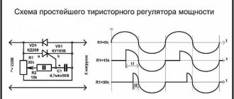
A fairly simple circuit of the device that will help regulate the power indicator on the soldering iron.
- VD - KD209 (or similar in its general characteristics).
- R 1 - resistance with a special rating of 15 kOhm.
- R2 is a resistor that has a special AC current rating of about 30 kOhm.
- Rn is the total load (in this case a special pendulum will be used instead).
Such a regulation device can control not only the positive half-cycle; for this reason, the power of the soldering iron will be several times less than the nominal one. Such a thyristor is controlled using a special circuit, which carries two resistances, as well as a capacitance. The charging time of the condensate (it will be regulated by a special resistance R2) affects the duration of opening of such a thyristor.
From the network
Single-phase AC motors also allow you to control the rotation of the rotor.
Collector machines
Such motors are found on electric drills, jigsaws and other tools. To reduce or increase the speed, it is enough, as in previous cases, to change the supply voltage. There are also solutions for this purpose. The structure connects directly to the network. The adjusting element is a triac, which is controlled by a dinistor. The triac is placed on the heat sink, the maximum load power is 600 W.
If there is a suitable LATR, you can do all this using it.
Two phase motor
The device, which has two windings - starting and working, is two-phase in principle. Unlike three-phase, it has the ability to change the rotor speed. The characteristic of its rotating magnetic field is not circular, but elliptical, which is due to its design. There are two possibilities for controlling the speed:
- Change the amplitude of the supply voltage (Uy),
- Phase - change the capacitance of the capacitor.
Such units are widely used in everyday life and in production.
Regular asynchronous
Three-phase electric machines, despite their ease of operation, have a number of characteristics that need to be taken into account. If you simply change the supply voltage, the torque will change within a small range, but no more. In order to regulate speed within a wide range, you need quite complex equipment, which is difficult and expensive to simply assemble and set up.
For this purpose, the industry has launched the production of frequency converters that help change the speed of the electric motor in the desired range.
The asynchronous machine gains momentum in accordance with the parameters set on the frequency driver, which can be changed in a wide range. The converter is the best solution for such engines.
Scheme number 1
There was a stabilized switching power supply that gave an output voltage of 17 volts and a current of 500 milliamps. A periodic change in voltage was required in the range of 11 - 13 volts. And the well-known voltage regulator circuit on one transistor coped with this perfectly. I added only an indication LED and a limiting resistor to it. By the way, the LED here is not only a “firefly” signaling the presence of output voltage. With the correct value of the limiting resistor, even a small change in the output voltage is reflected in the brightness of the LED, which provides additional information about its increase or decrease. The output voltage could be changed from 1.3 to 16 volts.
KT829, a powerful low-frequency silicon compound transistor, was installed on a powerful metal radiator and it seemed that, if necessary, it could easily withstand a heavy load, but a short circuit occurred in the consumer circuit and it burned out. The transistor has a high gain and is used in low-frequency amplifiers - you can really see its place there and not in voltage regulators.
On the left are removed electronic components, on the right are prepared for replacement. The difference in quantity is two items, but in terms of the quality of the circuits, the former and the one that was decided to be collected, it is incomparable. This begs the question: “Is it worth assembling a scheme with limited capabilities when there is a more advanced option “for the same money”, in the literal and figurative sense of this saying?”
DIY soldering iron power regulator: proven working circuits (6 pcs)
Not everyone likes to buy unknown things. And some people find it more pleasant to make a soldering iron power regulator with their own hands, because this is also experience. Most circuits are assembled using triacs and thyristors; now they are easier to find than transistors. They are also easier to work with, since they are either open or closed, which allows you to make circuits simpler.
Choose any case
Simple thyristor circuits
When choosing a power regulator circuit for a soldering iron, two things are important: power and parts availability. The soldering iron power regulator presented below is assembled using widely used parts that are not a problem to find. The maximum current is 10 A, which is more than enough to perform any kind of work and for soldering irons with a power of up to 100 W. The thyristor in this circuit is used KU202n
Pay attention to the bridge connection. There are many circuits with connection errors
This option is working. Tested more than once.
Temperature controller circuit for a soldering iron using a thyristor
When assembling the circuit, be sure to place the thyristor on the radiator; the larger it is, the better. The circuit is simple, but when it is turned on, it creates interference. You can’t listen to the radio nearby, and to remove interference, we connect a 200 pF capacitor in parallel with the load, and a choke in series. The choke parameters are selected depending on the regulated load, but since soldering irons are usually no more than 80-100 W, the choke can be made at 100 W. To do this, you will need a ferrite ring with an outer diameter of 20 mm, on which about 100 turns are wound with a wire with a cross-section of 0.4 mm².
Another drawback of the diagram translated above is that the soldering iron “itches” noticeably. Sometimes you can put up with this, sometimes you can’t. To eliminate this phenomenon, you can select the parameters of capacitor C1 so that when the variable resistor is set to maximum, the connected lamp barely glows.
On other elements but also without interference
The above regulator can be used for any load. Let's give another analogue, but using a different element base. You can regulate not only the power/temperature of the soldering iron, but also any other load with a small inductive component.
A modified circuit for regulating the power of a soldering iron and any other load with the ripple effect eliminated
There is pulsation here, but its frequency is high and it will not be perceived by our vision. So it can be used not only as a dimmer for a soldering iron, but also to regulate the light from a regular incandescent lamp. Is a diode bridge needed to regulate the heating power of a soldering iron? It won't hurt, but it's not necessary.
On a thyristor with high sensitivity
This circuit allows you to smoothly change the temperature of the soldering iron from 50% to 100%. There are two indicators - power and power. The power presence LED always lights up when turned on, but at 75% power the glow is brighter. The power indicator changes the intensity of the glow depending on the operating mode.
Power regulator for soldering iron without interference
In order for the regulator to fit into the case of a mobile phone charger, resistances are used of SMD type (1206). All resistors are installed on the board, except for R 10. Some can be composite (we assemble the required value from series-connected resistors).
For normal operation of the circuit, a sensitive thyristor (with a low control current) and a low state holding current (about 1 mA) is required. For example, KT503 (designed for voltage 400 V, control current 1 mA). The rest of the element base is indicated in the diagram.
If assembled, but the voltage is not adjustable
If the assembled regulator does not regulate anything - the temperature of the soldering iron does not change - the problem is in the thyristor. The scheme seems to be working, but nothing happens. The reason is a thyristor with low sensitivity. The currents flowing in the circuit are not sufficient to open. In this case, it is worth installing an analogue with higher sensitivity (lower control currents).
One of the housing options in which you can hide a homemade power regulator for a soldering iron
The regulator may still work, but the soldering iron begins to “itch.” This problem is solved by installing a choke at the output (in front of the soldering iron). The capacity must be selected - it depends on the soldering iron. The second solution is an analog control circuit, and this is a different circuit.
Well, if you have problems with operation, look for either faulty parts or incorrectly selected components. This is usually the problem.
Modern triac regulator circuit
Below is a modern circuit diagram of a triac power regulator. In order to understand the principle of operation of a power regulator on a triac, you need to imagine how it works.
Triacs, unlike thyristors, can operate not only in DC circuits, but also in AC circuits. This is their main difference. The triac also operates in key mode - either open or closed. To open the transition A1-A2, you need to apply a voltage of 2-5 V to the control electrode G relative to pin A1. The triac will open and not close until the voltage between terminals A1-A2 becomes zero.
The triac power regulator circuit operates as follows. AC mains voltage is supplied through the load (incandescent light bulb or soldering iron winding) to terminal A1 of triac VS2 and one of the terminals R2. When the middle terminal of resistor R2 is in the extreme left position, its resistance is 0 and when the voltage in the network begins to increase, capacitor C1 quickly charges. When C1 is charged to a voltage of 30 V, a breakdown of the dinistor VS1 occurs and the current flows to the control electrode G VS2 and the junction of the triac A1-A2 opens (graph 1).
When you turn the knob of variable resistor R2, its resistance will increase, the charging current of capacitor C1 will decrease and it will take more time for the voltage on it to reach 30 V. Therefore, the triac will open after some time. The greater the value of R2, the longer the charging time of C1 will be and the triac will open with a longer delay. This way, less energy will be supplied to the load.
The given classic circuit of a triac power regulator can also operate at a network voltage of 127, 24 or 12 V. It is only enough to reduce the value of the variable resistor. In the above circuit, the power is regulated not from 0 volts, but from 30, which is more than enough for practical use. This circuit was successfully repeated when repairing the electronic circuit for controlling the rotation speed of a blender motor.
How to make a current stabilizer for LEDs yourself
Making a stabilizer for LEDs with your own hands is carried out in several ways. It is advisable for a beginner to work with simple circuits.
Driver based
You will need to choose a chip that is difficult to burn out - LM317.
It will act as a stabilizer. The second element is a variable resistor with a resistance of 0.5 kOhm with three terminals and an adjustment knob. Assembly is carried out according to the following algorithm:
- Solder the conductors to the middle and extreme terminals of the resistor.
- Set the multimeter to resistance mode.
- Measure the parameters of the resistor - they should be equal to 500 Ohms.
- Check connections for integrity and assemble the circuit.
The output will be a module with a power of 1.5 A. To increase the current to 10 A, you can add a field switch.
Stabilizer for car lighting
Stabilizer L7812
To operate, you will need a linear device in the form of an L7812 microcircuit, two terminals, a 100n capacitor (1-2 pcs.), textolite material and a heat-shrinkable tube. Manufacturing is carried out step by step:
- Selecting a circuit for L7805 from the datasheet.
- Cut out the required size piece from the PCB.
- Mark the paths by making notches with a screwdriver.
- Solder the elements so that the input is on the left and the output is on the right.
- Make a housing from a thermal tube.
The stabilizing device can withstand up to 1.5 A load and is mounted on a radiator.
Chip contacts
Manufactured in a universal transistor package, allowing it to be placed on a board or heat sink. The most common model LM317 is found in the TO-220 case with the letter “T” at the end of the marking. The letter "t" indicates the housing type.
The pinout of the LM317 stabilizer is made using three contacts. If you look at the device from the front, the first pin on the left (Adj) is the adjustable pin, the middle pin (Vout) is the output, and the last pin on the right (Vin) is the input.
- Vin is a pin; it receives an input voltage that needs to be adjusted. For example, it may be supplied with 12V, which the device will step down to 10V at Vout.
- Vout is the pin to which the voltage is output. The surface of the heatsink is connected to this pin of the microcircuit.
- Adjustable (Adj) is a pin that allows you to adjust the output voltage through a trimmer resistor.
Found in various types of housings.
Contact numbers of different types of microcircuit housings.
Current and voltage regulator
The main operating elements of regulators are thyristors, as well as various types of capacitors and resistors. In high-voltage devices, magnetic amplifiers are additionally used. Modulators ensure smooth adjustments, and special filters help smooth out interference in the circuit. As a result, the electric current at the output becomes more stable than at the input.
DC and AC regulators have their own characteristics and differ in their main parameters and characteristics. For example, a DC voltage regulator has higher conductivity with minimal heat loss. The basis of the device is a diode-type thyristor, which provides a high pulse supply due to accelerated voltage conversion. Resistors used in the circuit must withstand a resistance value of up to 8 ohms. Due to this, heat losses are reduced, protecting the modulator from rapid overheating. The DC controller can function normally at a maximum temperature of 40C. This factor must be taken into account during operation. Field-effect transistors are located next to thyristors, since they only pass current in one direction. Due to this, the negative resistance will be maintained at a level not exceeding 8 ohms.
The main difference between the AC regulator is the use of exclusively triode-type thyristors in its design. However, field-effect transistors are used the same as in DC regulators. Capacitors installed in the circuit perform only stabilizing functions. High-pass filters are very rare. All problems associated with high temperatures are solved by installing pulse converters located next to the modulators. AC regulators whose power does not exceed 5 V use low-pass filters. Cathode control in such devices is performed by suppressing the input voltage.
During adjustments in the network, smooth current stabilization must be ensured. At high loads, the circuit is supplemented with reverse direction zener diodes. To connect them together, transistors and an inductor are used. Thus, the current regulator on the transistor performs current conversion quickly and losslessly.
Special attention should be paid to current regulators designed for active loads. The circuits of these devices use triode-type thyristors, capable of passing signals in both directions. The anode current in the circuit decreases during the period when the maximum frequency of this device decreases. The frequency may vary within the limits set for each device. The maximum output voltage will depend on this. To ensure this mode, field-type resistors and conventional capacitors capable of withstanding resistance up to 9 Ohms are used.
Very often, such regulators use pulsed zener diodes that are capable of overcoming the high amplitude of electromagnetic oscillations. Otherwise, as a result of a rapid increase in the temperature of the transistors, they will immediately become inoperative.
Methods for regulating phase voltage in the network
- There are several ways to regulate alternating voltage in thyristors: you can skip or disable the output on the regulator as many as four half-cycles (or periods) of alternating voltage. It can be turned on not at the beginning of the half-cycle of the mains voltage, but with a certain delay. During this time, the voltage at the output of the regulator will be equal to zero, and the total power will not be transferred to the output of the device. During the second part of the half-cycle, the thyristor will begin to conduct current and a special input voltage will appear at the output of the regulator.
- The delay time in most cases is called the opening angle of the thyristor, since during the zero angle value almost all the voltage from the input will go to the output, only the drop in the open area of the thyristor will begin to be lost. As the total thyristor angle increases, the voltage regulator will significantly reduce the output voltage parameter.
- The regulating characteristic of such a device during its operation, during active load, is carried out especially intensively. At an angle of 90 degrees (electrical), the output from the connector will be half the input voltage, and at a total angle of 180 electrical degrees, the output will be zero.
Based on the principles and features of phase voltage regulation, it is possible to construct certain regulation, stabilization, and, in some cases, soft start schemes. To achieve a smoother start, the voltage should be increased over time from zero to the maximum value. Thus, during the opening of the thyristor, the maximum value should change to zero.
AC Models
The AC regulator differs in that thyristors are used only of the triode type. In turn, transistors are standardly used in the field-field type. Capacitors in the circuit are used only for stabilization. You can find high-frequency filters in devices of this type, but rarely. Problems with high temperatures in models are solved using a pulse converter. It is installed in the system behind the modulator. Low-frequency filters are used in regulators with a power of up to 5 V. Control of the cathode in the device is carried out by suppressing the input voltage.
Stabilization of the current in the network occurs smoothly. In order to cope with high loads, reverse zener diodes are used in some cases. They are connected by transistors using a choke. In this case, the current regulator must be able to withstand a maximum load of 7 A. In this case, the level of maximum resistance in the system must not exceed 9 Ohms. In this case, you can hope for a quick conversion process.
Analogues of KU202N
Like any other devices, the domestic thyristor KU202 has a foreign analogue , which, according to its parameters, belongs to the same category of components. Foreign manufacturers have long abandoned the production of this form factor in terms of power of thyristors in a metal case. Only elements in the TO220 transistor package will be available on the market. Therefore, in any case, you will have to make design changes to the board and the mounting location in particular.
Foreign analogues of the KU202N thyristor include the following devices:
The parameters differ slightly from the component described above, and the average current is 7.5 A. You can also use the newer Russian element T112-10 in the circuits. It also has a metal body with a threaded outlet, but its dimensions will be somewhat smaller.
Design and operating principle
The stabilizer ensures constant current when it deviates.
The stabilizer ensures constant operating current of LED diodes when it deviates from the norm. It prevents overheating and burnout of LEDs, maintains constant flow during voltage surges or battery discharge.
The simplest device consists of a transformer, a rectifier bridge connected to resistors and capacitors. The action of the stabilizer is based on the following principles:
- supplying current to the transformer and changing its limiting frequency to the mains frequency - 50 Hz;
- voltage adjustment to increase and decrease with subsequent frequency equalization to 30 Hz.
The conversion process also uses high-voltage rectifiers. They determine the polarity. Stabilization of the electric current is carried out using capacitors. Resistors are used to reduce interference.
How to avoid 3 common mistakes when working with a triac.
- The letter after the triac code indicates its maximum operating voltage: A – 100V, B – 200V, C – 300V, D – 400V. Therefore, you should not take a device with the letters A and B to adjust 0-220 volts - such a triac will fail.
- A triac, like any other semiconductor device, gets very hot during operation; you should consider installing a radiator or an active cooling system.
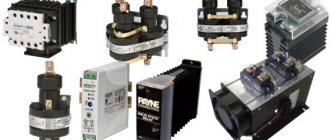
- When using a triac in load circuits with high current consumption, it is necessary to clearly select the device for the stated purpose. For example, a chandelier with 5 bulbs of 100 watts each will consume a total current of 2 amperes. When choosing from the catalog, you need to look at the maximum operating current of the device. Thus, the MAS97A6 triac is designed for only 0.4 amperes and will not withstand such a load, while the MAS228A8 is capable of passing up to 8 A and is suitable for this load.
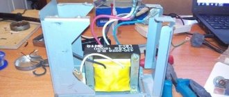
Construction and details.
The regulator is assembled in the power supply housing of the once popular “Electronics B3-36” calculator.
The triac and potentiometer are placed on a steel angle made of steel 0.5 mm thick. The corner is screwed to the body with two M2.5 screws using insulating washers.
Resistors R2, R3 and neon lamp HL1 are dressed in an insulating tube (cambric) and mounted using a hinged mounting method on other electrical elements of the structure.
To increase the reliability of fastening the plug pins, I had to solder several turns of thick copper wire onto them.
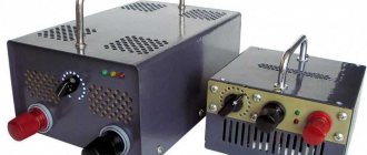
This is what the power regulators I've been using for years look like.
| to see this player. |
And this is a 4-second video that allows you to make sure that it all works. The load is a 100 Watt incandescent lamp.
Introduction.
Many years ago, I made a similar regulator when I had to earn extra money repairing radios at a customer’s home. The regulator turned out to be so convenient that over time I made another copy, since the first sample was constantly installed as an exhaust fan speed regulator. https://oldoctober.com/
By the way, this fan is from the Know How series, as it is equipped with an air shut-off valve of my own design. Description of the design >>> The material can be useful for residents living on the top floors of high-rise buildings and who have a good sense of smell.
The power of the connected load depends on the thyristor used and its cooling conditions. If a large thyristor or triac of the KU208G type is used, then you can safely connect a load of 200... 300 Watts. When using a small thyristor, type B169D, the power will be limited to 100 Watts.
Types of power regulators
Different power regulators are used for different purposes.
Thyristor control device
The design of the device is quite simple. Typically, thyristors are used in low-power devices. A thyristor thermostat consists of bipolar transistors, the thyristor itself, a capacitor and several resistors.
Thyristor transistor regulator
Transistors form a pulse signal; when the capacitor voltage is equalized with the operating voltage, they open. The electrical signal is transmitted to the output of the thyristor, after which the capacitor is discharged and the key is locked. The entire sequence of actions is repeated cyclically.
Note! The amount of delay is inversely proportional to the power supplied to the load
Triac power converter
A triac is a subtype of a thyristor, in which there are slightly more pn transitions, which is why its operating principle is somewhat different. But a triac is often considered a separate type of power stabilizer. The design consists of 2 thyristors connected in parallel and having common control.
For your information! This is where the name “triac” comes from - “symmetrical thyristors”. Sometimes it is also called TRIAC.
Diagram of 2 parallel connected thyristors (left) and triac (right)
The diagram shows that the triac has the designations T1 and T2 instead of the anode and cathode. This is because the concepts of “cathode” and “anode” in this case do not make sense, since electric current can exit through both terminals.
Triac universal regulators have a number of advantages, including low price, long service life and the absence of moving contacts, which can be sources of interference. But there are also disadvantages: susceptibility to interference and noise, lack of support for high switching frequencies.
Important! They are not used in high-power industrial installations; instead, thyristors or IGBT transistors are used.
Phase transformation method
Phase transformation occurs in so-called dimmers. Such devices are used, for example, to change the lighting intensity of halogen or incandescent lamps. The electrical circuit is usually implemented on special microcontrollers, which use their own integrated voltage reduction circuit. Due to their design, dimmers can smoothly reduce power.
LED dimmer
The disadvantages of such devices are high sensitivity to interference, high ripple factor and low signal power factor at the output. To stabilize the dimmer, dual thyristors are used.
Using modern element base
Old radio components are good because they are “oak” in terms of operational reliability. But they are already really old. For many, their time resource is at its limit and they do not last as long as “fresh” ones. This is the first problem. And secondly, they are becoming increasingly difficult to find. It’s good that there are already many soldering iron regulator circuits based on the new element base. Some of them are simple, others are more complex; various types of modern radio components are used.
Regulator circuit for a soldering iron without interference on the chip
This option cannot be called simple, but it does not emit interference into the network. With so many electronics in every home, this can be important. If you solder only occasionally, you don’t have to pay attention to it. But if you often sit with a soldering iron, interference can cause serious inconvenience.
This circuit can regulate a load of up to 2 kW and provides a smooth change from 0 to maximum.
Homemade soldering iron regulator without interference
According to the element base. The K561LA7 microcircuit can be replaced with a K176LA7. Variable resistor R1 - any of group A. The remaining resistors are better than MLT, capacitors C1, C3 are ceramic. The diodes in the circuit are KD503A; KD514A and KD522A can be replaced. There is also the option of replacing the KT361V transistor with a KT326V or KT361A.
Based on PR1500S phase power regulators
This circuit uses a phase power regulator. Apart from this, the regulator uses only a couple of parts, so assembly time is minimal and it is almost impossible to make a mistake.
DIY soldering iron tip temperature regulator
You will only need a variable resistor, maybe with a switch - then you won’t have to take the soldering iron out of the network. To eliminate interference, you will need a 100 pF capacitor, 630 V, preferably a special film one for filters. The only thing that may be difficult is winding the choke; its parameters are in the table.
Parameters for winding the choke
You will need a ferrite ring with an outer diameter of 20 mm. The greater the permeability of ferrite, the better. This phase regulator can regulate loads up to 1.5 kW, so you can choose any of their columns. You can do it with a reserve, you never know what you want to adjust later. The wire is naturally varnished copper, especially for winding chokes.
What happened after assembly
When assembling for the inductor and phase regulator, it is better to make a heat sink. It is especially useful when working with heavy loads. You can get by with a soldering iron, but you never know, connect it later and it’s better to assemble it right away with a safety margin.
On the optosimistor MOS204x/306x/308x
The circuit has been tested many times and works perfectly without any problems. It is advisable to use optical triacs of the indicated brands, since they open when the voltage crosses zero
The state of the LED does not matter. All others work on a different principle, so the circuit will need to be redone for them. The circuit also contains a 555 series bipolar timer
Finding it is not a problem, the price is normal.
Soldering iron power regulator using optosimistors
All components are selected to have miniature dimensions so that the finished board fits into the case when charging a mobile phone. The value of resistor R5 depends on the type of LED used. On red the voltage drop is 1.6-2 V, on green 1.9-4 V, on yellow 2.1-2.2 V, on blue 2.5-3.7 V. Accordingly, the resistor is selected depending on the actual parameters .
With PWM controller
The modern element base is very extensive, and the same problems can be solved in different ways. For example, use a PWM controller for a power regulator. Any model operating at a frequency of 0.5-1 Hz is suitable for this circuit. The switching element is a field-effect transistor; it can be found on old motherboards or purchased. Its type is not specified, but any n-channel transistor with a voltage of at least 12 V, a current of 6 A and a power of 60 W is suitable.
Soldering iron regulator on a PWM controller and field-effect transistor
The VD3 LED is an optional part of the circuit, but it blinks at different frequencies depending on the heating. Once you get the hang of it, it’s easy to navigate and you don’t have to look at the control knob. But in general, it can be safely thrown out of the scheme
Please note: the power buses from the microcircuit run parallel to the wires, this minimizes the influence of a more powerful load
Specifications
Let's consider the technical parameters of the KU 202e series thyristor. This series presents domestic low-power devices, the main use of which is limited to household appliances: it is used to operate electric furnaces, heaters, etc.
The drawing below shows the pinout and main parts of the thyristor.
Photo – ku 202
- Set reverse on-state voltage (max) 100 V
- Closed voltage 100 V
- Pulse in open position – 30 A
- Repeated pulse in open position 10 A
- Average voltage =0.2 V
- Set current in open position
Photo – thyristor Ku202n
The price of a thyristor depends on its brand and characteristics. We recommend buying domestic devices - they are more durable and affordable. In spontaneous markets you can buy a high-quality, powerful converter for up to a hundred rubles.
Thyristor KU202N belongs to the group of triode devices with a p - n - p - n structure. The junctions are created by planar diffusion of silicon. The thyristor is designed to switch high voltages using small levels through an additional output. Depending on the switching circuit, it can open or close, providing the required operating modes of the device. It is used in blocking systems, protection systems, servo drives, remotely controlled switching systems, chargers as a switch or charge current regulator.
You can buy the KU 202N thyristor in many other places, because it is a fairly common component. Moreover, its price is much lower than imported analogues. It can also be found in many Soviet devices, from power supplies to switching devices.
Scheme number 2
The new circuit also has a three-pin electrical connection. component (but this is no longer a transistor) constant and variable resistors, an LED with its own limiter. Only two electrolytic capacitors have been added. Typically, typical diagrams indicate the minimum values of C1 and C2 (C1=0.1 µF and C2=1 µF) which are necessary for stable operation of the stabilizer. In practice, capacitance values range from tens to hundreds of microfarads. The containers should be located as close to the chip as possible. For large capacities, the condition C1>>C2 is required. If the capacitance of the capacitor at the output exceeds the capacitance of the capacitor at the input, then a situation arises in which the output voltage exceeds the input, which leads to damage to the stabilizer microcircuit. To exclude it, install a protective diode VD1.
This scheme has completely different possibilities. Input voltage is from 5 to 40 volts, output voltage is 1.2 - 37 volts. Yes, there is an input-output voltage drop of approximately 3.5 volts, but there are no roses without thorns. But the KR142EN12A microcircuit, called a linear adjustable voltage stabilizer, has good protection against excess load current and short-term protection against short circuits at the output. Its operating temperature is up to + 70 degrees Celsius, works with an external voltage divider. Output load current is up to 1 A during long-term operation and 1.5 A during short-term operation. The maximum permissible power when operating without a heat sink is 1 W, if the microcircuit is installed on a radiator of sufficient size (100 cm2) then P max. = 10 W.
Methods for regulating phase voltage in the network
- There are several ways to regulate alternating voltage in thyristors: you can skip or disable the output on the regulator as many as four half-cycles (or periods) of alternating voltage. It can be turned on not at the beginning of the half-cycle of the mains voltage, but with a certain delay. During this time, the voltage at the output of the regulator will be equal to zero, and the total power will not be transferred to the output of the device. During the second part of the half-cycle, the thyristor will begin to conduct current and a special input voltage will appear at the output of the regulator.
- The delay time in most cases is called the opening angle of the thyristor, since during the zero angle value almost all the voltage from the input will go to the output, only the drop in the open area of the thyristor will begin to be lost. As the total thyristor angle increases, the voltage regulator will significantly reduce the output voltage parameter.
- The regulating characteristic of such a device during its operation, during active load, is carried out especially intensively. At an angle of 90 degrees (electrical), the output from the connector will be half the input voltage, and at a total angle of 180 electrical degrees, the output will be zero.
Based on the principles and features of phase voltage regulation, it is possible to construct certain regulation, stabilization, and, in some cases, soft start schemes. To achieve a smoother start, the voltage should be increased over time from zero to the maximum value. Thus, during the opening of the thyristor, the maximum value should change to zero.