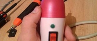
Hi all! I'm already exhausted and don't know what to do. In general, I have a semi-automatic BestWeld Master 132A. Does not cook in a protective gas environment. It welds fine with flux-cored wire, but it craps on the seams like a bird, and doesn’t want copper-coated wire in carbon dioxide. When you try to weld copper-plated with carbon dioxide, the welding simply spits out and does not weld anything. You just end up with drops of scale on the metal and that’s it. I've already tried everything, played with the settings, measured the voltage, and changed the polarities. There's no point. I’m already sinning with bad gas... Tell me, who has had this happen!
Some repair features
Many years of experience show that in some cases the weld is weak due to the poor quality of the shielding gas.
Or due to its unstable supply to the arc burning zone.
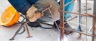
In such cases, it is necessary to inspect the entire gas supply path and the burner, which the welder holds with his own hands during work.
This tool should always be kept in working order. Protect it from damage and contamination.
All preventive maintenance prescribed in the operating instructions must be carried out strictly.
If these requirements are met, the semi-automatic welding machine will operate flawlessly.
Why does a semi-automatic cook poorly? What can be done?
First of all, try to measure the voltage, set it to maximum and wire feed to minimum. Very often, a lot depends on the voltage in the garage. If it is less than 220 Volts, then a bad Chinese semi-automatic machine will not cook properly. More precisely, it will try to heat the welding wire, but it will remain stuck to the metal, only turning a little red.
It’s also worth checking exactly what polarity is set. In addition, it would be a good idea to look at exactly where the wires are connected. Very often, novice welders make mistakes precisely at the stage of connecting a semi-automatic machine. As a result of this, they connect the wires to the welding mode “without gas” and try to weld with carbon dioxide.
Repair of inverter welding machines
The design of welding inverters uses high-frequency electronics, which, unfortunately, not only significantly increases the performance and functionality of the device, but also often becomes capricious.
Where to start repairing a welding inverter?
Repair of inverter welding machines - regardless of the manufacturer and model - begins with a banal “opening” of the equipment and an external inspection of the “internals”. Perhaps already at this stage you will be lucky and you will be able to “calculate” the failed part by its appearance. If at first glance everything looks as usual, proceed to diagnosis.
Diagnostics and repair
The first step is to check the fuses located on the control board. After dismantling the board, determine the broken element with a tester or ohmmeter, carefully replace it and reassemble the inverter. If all the fuses are working, the problem may be the faults described below in the circuit.
Often repair of a welding inverter is required as a result of a breakdown
field-effect transistors, which are the “weak link”. External signs of failure, which were mentioned in the previous paragraph, practically do not appear in these elements. A cracked case and melted leads are extremely rare occurrences. It is for this reason that burnt transistors can only be found by testing them sequentially with a multimeter.
The next stage of diagnostics is checking the driver elements that control the operation of field-effect transistors. Failed elements can be identified using an ohmmeter.
A little advice: in order not to get confused, ring both transistors and driver elements according to the diagram of your inverter welding machine, having previously chosen the direction (for example, from left to right). Then the risk of missing something or forgetting about any element will simply disappear.
If the breakdown is still not detected, we complete the diagnosis by checking the main parts of the rectifiers (we are talking about diode bridges). They, being the most reliable elements of an inverter welding machine, break down extremely rarely, but it is still worth taking into account the likelihood of failure. In order to diagnose the diodes installed on the radiators, you should first remove them from the board. The resistance of a good diode changes from “+” to “-” and vice versa. The rest are mercilessly thrown away.
Repair of inverter welding machines when the breakdowns described above are identified consists of replacing the elements that “failed”.
Some tips for repairing welding inverters
- Transistors often fail due to overheating. So once you get to the inside of the device, just in case, change the thermal paste at the point of contact with the heat sink plate.
- Even if the breakdown is fixed, take a look at all the contacts. Clean up and reconnect the ones that don't look very nice.
Impact of equipment and technology
To protect against welding spatter, first of all, you need to pay attention to the use of high-quality equipment and electrodes. Good results can be achieved by using inverter semi-automatic machines.
When operating, these devices produce a very even current, which allows you to obtain a stable arc.
The cost of inverter semi-automatic machines reaches high values, but more expensive equipment does not always completely eliminate welding spatter.
Improvement in welding quality also occurs when switching to the use of three-phase current.
Working in a gas environment almost completely eliminates welding spatter. To do this, use a mixture of argon and carbon dioxide in proportions of 95% argon to 5% carbon dioxide.
When choosing parameters, you need to pay attention to the value of the welding current. It is its overestimated value that contributes to the formation and scattering of molten metal.
Electrodes must be used in accordance with the welding mode, their characteristics must correspond to the properties of the materials being welded, which provides protection against the formation of splashes. The use of wet, damp electrodes, as well as rods with cracked or peeling coating is not allowed .
When preparing products for welding, they should be thoroughly cleaned of dirt, rust, and soot. Oily parts must be degreased. The cutting of seam edges must be carried out in accordance with the requirements of the work technology.
By following the above tips, you can significantly reduce the amount of splashing. But small splashes still form, sticking to the metal.
If the design or structure is of a low degree of responsibility, and strict requirements are not imposed on its appearance, one could stop at using these measures. Otherwise, you have to eliminate the consequences.
Setting the wire feed speed
p, blockquote 10,0,0,0,0 –>
- The wire feed speed controller also serves another purpose - it regulates the current. Voltage and current are related and, to some extent, are based on the size of the wire and its speed. In a semi-automatic machine, the set voltage remains unchanged, but the current varies slightly depending on the wire feed speed and the electrode (wire) stick out. Thus, the faster the wire is fed to the welding site, the greater the current strength and the higher the welding temperature, but for a specific, established type of voltage this is only a small range of changes in current strength.
- The wire outside the welding process (without an electric arc) moves faster. When an arc is formed, the speed of the wire decreases.
- How do I know if my wire feed settings are correct? To do this you need to try welding. If the speed is too high for your voltage setting, the wire will bend when it touches the metal before it has time to melt, and there will be a lot of spatter. If the speed is too slow for your voltage setting, the wire will burn before it touches the metal and the tip will clog. Thus, if the wire feed speed is incorrectly set, welding will not work at all. This parameter must be adjusted experimentally. It is important to set the correct voltage for the specific thickness of the metal being welded and try welding, and adjust the wire feed speed during the process.
see also
Comments 95
I had this kind of crap, everything seemed to be set up normally, I got the wire for free - they installed it - it spits and the tips are scorching, they thought the device was defective, but they took out the whole chip when the wire stopped feeding, they removed the cover and in the reel... ATTENTION... the wire is COILED! ))))) they gave us the coil in a box (it was purchased at EPICENTER, blue label, I won’t tell you the name)
Thanks everyone guys. everything worked. For the sake of experiment, I bought a new one-kilogram skein of wire and everything was welded perfectly)
I think it's a carbon dioxide issue. Turn off the gas if the difference is small - that's where the dog rummaged
thank you) It was a wire issue)
The gas pressure may also be too high. try to reduce it to the minimum possible. option - use a propane frog. just smash it into the hose. It doesn't give much gas, but it's enough.
network voltage. How much does it sag when you cook it?
I don’t remember right now... My father measured it that year. She eats less than an electric kettle
Have you already thrown out the Chinese crap and bought a standard welder?
And buy branded shit in 3rd road assembled in China?
everything is much simpler. I bought Triton 160 instead of China. all the problems are gone. z.ch is available in any radio and auto store. Cooks even at 180 volts without any stabilizers. I've been plowing the same one at work for 10-15 years, look for a used one, I haven't seen any new ones like this.
It was similar. Something “died” inside, it was repaired under warranty and everything is good
no need to disassemble anything, first of all change the copper-plated welding wire, I had this - www.drive2.ru/l/7736859/
thanks) I'll try tomorrow
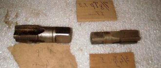
change the contact for the burners, you most likely have 1mm, but for the copper plate 0.8 you need 0.8 then everything will be smooth and look at how much the broach roller costs, it should also be 0.8 otherwise there will be jerks. But regarding the contactor, if it is larger than the wire, then the current is not constantly transferred from it to the wire and there is no arc.
and roller 0.8 and tip 0.8...
how much wire? remove the tip (insulator) and see if there is any scale between it and the contactor, if not, try not to touch the part you are cooking, the current is leaking or there is no contact in the burner. for a parashkova (from the word parasha, it shouldn’t be cooked at all; it doesn’t cook, it just clogs the seam) a smaller current is needed.
and wire 0.8. I'll check tomorrow. And in general, I often read everything. Well, you can’t argue about the powder one, but I had no choice. I cooked it with it. but I'm really tired of it. so I decided to somehow adjust the carbon dioxide
I would completely disassemble the burner and the sleeve might be twisted or frayed somewhere, or the channel through which the wire goes is clogged with dust from the wire, it’s better to install Teflon, it costs 300 for 5 meters www.svarbi.ru/cat/kanaly-importnye-gorelki/ and it’s not much to look at the rollers clamp the wire, there are no jagged marks left on it, and they quickly wipe the channel
I would completely disassemble the burner and the sleeve might be twisted or frayed somewhere, or the channel through which the wire goes is clogged with dust from the wire, it’s better to install Teflon, it costs 300 for 5 meters www.svarbi.ru/cat/kanaly-importnye-gorelki/ and it’s not much to look at the rollers clamp the wire, there are no jagged marks left on it, and they quickly wipe the channel
But what if you press the roller tightly, the wire will also move in jerks, as if it’s spitting or shaking?
Yes . you need to clamp it so that there are no nicks from the roller left on the wire, otherwise they will cling to the channel and rub off. It took me a long time to select the correct clamping force.
Thank you, yes, I’m stuck tomorrow, I’ll take a look, then it’s normal, another hole is cooking, it starts to triple, the slides grow in the form of a volcano crater with a hole
this is because the contactor is broken and there is no current transfer to the wire, or there is scale in the mouthpiece or there is no insulation. if the channel is a drain and it is polyethylene, then it needs to be changed every 15 kg of wire; if Teflon is like benzene, then 40-50 kg. and also in the tube on which the mouthpiece is put on and the contact piece is twisted, where the bend of the wire is machined into a groove and the wire clings.
Yes, my tip was completely broken; I even drilled it because there was no place to buy it. So I cooked it with what I had. But after installing a new one, the same thing happens as before, even the wire sticks more often than on the broken one. I no longer bother with pliers always nearby. Today I’ll lower the video and take a look and reduce the pressure. Sometimes it cooks like a zinny sound and everything is not even normal, you look at the drop so it’s not there, it smoothly completely flooded the soldering area, my pressure is 2.5-3-4, the gearbox is dancing, it’s bad, but there’s no choice to finish cooking, but for yourself to understand the nuances of the work in order to be a little bit more understanding of that what's happening.
It is necessary that the current collector is exactly one to one under the wire, otherwise the wire inside it will burn and stick and will just spit out.
Thank you, I understand, I just got a tip for 0.8, I’ll change it. Now it’s 1.0. Thank you
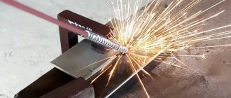
I started with 0.9, but the wire was welded in it, I foolishly set it to 1.0 and it got even worse, and only when I set 0.8 did it start to cook like in the photo
Hello thank you very much! The kids just sent me new tips, there’s even one for 0.6 and there’s one tip for 0.8. It’s been raining since the morning, there was snow, and there’s snow again, there’s a strong wind. As soon as the weather gets better, I’ll definitely try for everyone’s advice, thank you very much and good luck in any endeavor!
change the contact for the burners, you most likely have 1mm, but for the copper plate 0.8 you need 0.8 then everything will be smooth and look at how much the broach roller costs, it should also be 0.8 otherwise there will be jerks. But regarding the contactor, if it is larger than the wire, then the current is not constantly transferred from it to the wire and there is no arc.
Semi-automatic welding machine: operating principle
In order not to “kill” the device when using a semi-automatic welding machine. To avoid injury, you should know about the safety rules and the operating principle of the device.
The semiautomatic welding machine consists of:
- housing containing a powerful transformer;
- hose for supplying current and gas to the burner;
- cables for connecting to ground and the electrical network;
- wire feed mechanism.
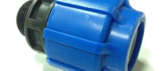
Also, for semi-automatic welding, you will need to purchase a reel with a special welding wire and a cylinder of carbon dioxide.
The operating principle of the semi-automatic device is as follows:
- The welding current is supplied to the torch simultaneously with the shielding gas.
- The torch uses a welding wire as an electrode, which is fed automatically using a special mechanism.
- An electric arc is formed between the product being welded and the wire, which melts the metal in a protective gas environment, which allows you to obtain a high-quality weld without oxides.
The basic safety rules when working with semi-automatic welding machines are as follows:
- the body of the welding machine must be grounded;
- it is prohibited to use the device even with minor mechanical damage or any other malfunctions;
- in case of significant interruptions in work, be sure to disconnect the device from the electrical network and turn off the supply of protective gas;
- do not work near flammable and explosive substances;
- Use a protective mask and gloves while working.
As soon as the basic principles of working with a semi-automatic machine are mastered, you can begin practical work.
How to clean power elements
Like the deck in which the coil (feeding mechanism) is located, the compartment in which the electrical equipment is located - the electronic boards of the welder, also periodically needs to be blown out and cleaned of dust and various contaminants using compressed air. However, in this case, you need to work carefully and set a low pressure so that the flow of compressed air masses during purging does not damage the electrical circuits on the welding machine boards.
In some cases, layers of dust that appear on electrical equipment and power elements begin to tightly cake and compact over time. In this case, removing such contaminants with blowing alone will be very problematic. Therefore, in order to properly clean the power elements of the welding machine, you need to:
- Using compressed air masses, purify the electrical installation of the equipment.
- Remove loose layers of dirt or dust.
- Using a hard paint brush made of nylon, loosen the tightly crumpled layers of dust.
- Perform re-purge.
It is necessary to carry out the procedure for loosening large layers of compacted dust and blowing until all contaminants are removed from the surface of the power elements. Cleaning modules with electronics and power boards must be carried out carefully so as not to damage their integrity.
Polarity when welding semi-automatically
Before welding, you need to decide which polarity you will use.
p, blockquote 11,0,0,0,0 –>
Plain copper-clad wire that is used with shielding gas should be used with reverse polarity when positive is applied to the wire. Straight polarity is used when the semi-automatic machine has flux wire installed, which is used without gas. In this case, a minus is applied to the wire, and a plus is applied to the metal being welded through the terminal. Thus, maximum heat generation is generated on the wire. This is necessary so that the flux in it can work properly.
p, blockquote 12,0,0,0,0 –>
If you use the wrong polarity for a certain electrode (in the case of a semi-automatic wire), then the strength of the weld will be poor. If the wrong polarity is used, there will be a lot of spatter, poor welding penetration and the welding arc will be difficult to control.
p, blockquote 13,1,0,0,0 –>
To change the polarity, you need to open the cover of the semiautomatic device and swap the terminals. Next to the terminals there is a table specifying the order of the terminals.
p, blockquote 14,0,0,0,0 –>
Welding wire
p, blockquote 15,0,0,0,0 –>
The semi-automatic machine can use two types of wires: plain copper-coated wire and flux-coated wire.
p, blockquote 16,0,0,0,0 –>
- Simple wire for semi-automatic welding is used with shielding gas and does not have any additives that can “resist” corrosion and contamination. Therefore, the surface must be prepared carefully.
- The second type of wire has a flux in the center, which, when burned, forms a protective gas. Thus, you can do without a gas cylinder. This wire creates deeper penetration when welding than conventional wire with gas. Flux-cored wire creates a lot of spatter and slag in the welding area, which must be cleaned up after welding is complete. When welding with such wire, minimal surface preparation is required, minor contamination is forgiven. This wire also works well when it's windy outside. For flux-cored welding, the machine must be set to straight polarity (see above).
- The greater the thickness of the metal being welded, the larger the diameter of the wire you need to use, since larger diameter wire conducts more electricity and gives more heat and better penetration.
Methods of protection against adhesion of welding spatter
When performing welding work, spattering of the electrode metal and its sticking to the surfaces of the parts being connected or the seam are very often observed.
When accepting welding work, depending on the degree of responsibility of the structure, adhering drops of metal may be perceived as a serious defect.
Welding spatter protection is a definite concern for new welders. To prevent splashing, it is necessary to follow the technology and use protective compounds.
Automatic shutdown of the welding device
Operation of a semi-automatic welding machine.
In this situation, when connected to the network, a spontaneous shutdown occurs, as the protective element is triggered. Such problems most often occur during the closing of a high voltage circuit. Usually the wires and the housing or the wiring itself are shorted. The protection may operate due to a short circuit between the coil turns or magnetic circuit elements.
Read more: Diode strip for cars
If repairs are necessary, you should disconnect the welding machine from the power supply, locate the source of the problem and correct it - this could be restoring the insulation, replacing the capacitor and other possible malfunctions.
Additional problems when the device is faulty
- Spontaneous interruption of the arc without the possibility of resuming work. With such a malfunction, instead of an arc, only sparks appear. This occurs if there is a breakdown in the high voltage winding, from a short circuit in the welding wires, or if the connection of the wires to the terminals of the device is broken.
- Excess current in the network without load. This problem may arise due to short-circuiting of the winding turns, which can be eliminated by restoring the insulation or by completely changing the winding on the welding reel.
Why does water in oil cause shooting?
When the temperature reaches 100 degrees, water changes from liquid to gaseous state. It expands greatly. When the heating process proceeds very quickly, expansion also occurs intensely, explosively. The oil can be heated to 160-180 degrees, under such conditions the water evaporates instantly, a drop of it creates a micro-explosion due to a very fast, strong increase in volume. The steam moves the oil violently as it leaves the pan, creating agitation and splatter. The process is relevant for any type of fat used in cooking - for vegetable and animal oils.
Interesting: Why is Christmas on January 7th? Reasons, photos and videos
Anti-caking agents
Sometimes removing splashes of molten metal is impossible using mechanical methods, that is, cutting down or grinding. Problems arise due to the location of the seam in hard-to-reach places.
In this case, the surfaces of the parts to be joined by welding are pre-treated around the weld area with means to protect against welding spatter. Such products are a paste or liquid against the adhesion of molten metal.
Currently, there are many different means of protection. The retail network has ready-made products from the BINZEL, ESAB, E-WELD, and INDUSVAR brands.
According to the method of application, they are divided into:
- produced in the form of liquids packaged in canisters and bottles. The protection is applied by brush or spray through a spray bottle;
- produced in the form of aerosols in special bottles;
- in the form of pastes, packaged in metal or plastic jars with a wide neck for ease of use.
Each product must be used in accordance with the manufacturer's instructions.
Very often, experienced welders use their own compound recipes, developed over the years, to prevent the adhesion of spatter.
As a means of protection, you can use a solution of chalk in water. It is desirable that the consistency be close to paste. Using a brush, this solution is used to cover the part around the future seam, but the edges themselves must remain clean.
After welding work, it is necessary to thoroughly clean the surfaces of the seam and metal from the applied product. Many anti-splash formulations include oils, greases, and other substances that significantly reduce the adhesive properties of the coating.
If necessary, surfaces must be degreased, which improves the quality of further processing of products and structures.
source
Getting started with a semi-automatic welding machine
To start working, the semi-automatic welding machine must be completely ready for the welding process. The wire must be installed and the gas cylinder connected. It is necessary to install a ground clamp on the metal being welded. It must be installed at a distance of 15 to 50 cm from the welding zone. The metal must be free of rust, paint, oils and dirt. Any slight resistance will affect the welding process. Dirty metal during welding will cause spatter and burn through, as well as fire.
p, blockquote 18,0,0,0,0 –>
p, blockquote 19,0,0,1,0 –>
Correctly adjusted voltage and wire feed speed should result in good welding flow. The correct settings will produce the characteristic hissing-buzzing sound that all welders know well. More details about the welding process can be found in the article “MIG / MAG semi-automatic welding technology”.
p, blockquote 20,0,0,0,0 –>
Reasons for appearance
Welding spatter usually occurs at the moment the arc is ignited, while the current is at its highest. When the electrode touches the connected parts at the moment of a short circuit, the metal of the electrode, subjected to an electrodynamic shock, scatters and settles in drops in the form of balls on the surface.
In some cases, welding the droplets to the base metal can be very strong. The defect is clearly visible. It can be removed by cutting off frozen drops or grinding with special tools.
In addition to this case, welding spatter most often occurs when welding semi-automatically using single-phase current during power surges.
The amount of spatter increases greatly if welding is performed on a rusty and dirty metal surface.
Thus, the main causes of welding spatter are:
- poor quality electrodes;
- incorrect choice of welding mode and parameters;
- low quality of preparation of products for welding;
- lack of protection of the product from sticking.
By eliminating all or part of these problems, you can ensure high quality work with a minimum amount of welding spatter.
Tags
The flux cored wire welds the wire when the wire stopped more than the wire tone of the wire and the wire on which the wire comes from the wire better clamps the wire not a semi-automatic welds in jerks. Does not weld in the environment when trying to weld in a copper-plated shop. cooks even the one you cook when the wire stops on the wire and the wire is not clamped the wire is not clamped
wiremenu large was roller there are tips no try contact person metal became thank you bad bought more generally with jerks pressure set less completely wire channel inside better starts new me share ok understand look connections gearbox changed
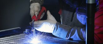
Spatter during manual arc welding with coated electrodes and ways to reduce it
Over the past 20 years, in industrialized countries, the share of metal deposited by manual arc welding has decreased by almost 3 times. There is reason to believe that in the near future the share of manual arc welding (for deposited metal) in industrial countries will stabilize at 15-25%, and in the world as a whole the decline will be mainly due to developing countries and China. The predominant use of this welding method in construction (at least 85-90% of the total volume of welding work) will continue in the coming years.
You need to know this!
First of all, before you start working, you need to decide on the welding mode - a set of factors (current strength, arc length, arc voltage, welding speed) that determine how the process proceeds. An incorrectly set mode leads to the appearance of defects during operation, which in turn affect the strength of the product.
Important to remember! As the current increases, the length of the welding arc decreases and in order for it not to become too short, it is necessary to increase the voltage. If the current is excessive, burn-throughs may occur - molten metal leaking out of the weld pool. The voltage is increased manually using a step switch. In the case of a long arc, it is possible that air can get into it, which leads to pore formation and increases the risk of undercutting - thinning of the metal at the weld site. An arc that is too long is recognized by a characteristic hissing sound.
Wire overhang
Wire stickout is the distance between the end of the tip and the end of the wire. When using carbon dioxide or mixtures, keep the overhang between 0.6 mm and 1 cm. Too much overhang will weaken the arch. The smaller the wire stickout, the more stable the electric arc and the better penetration will be obtained even with low voltage. Thus, the best wire overhang is as short as possible. However, wire protrusion may depend on how far the torch tip is recessed into the gas nozzle. The further the tip is recessed into the nozzle, the longer the wire extension should be.