Any welder knows what a welding mode is, but not everyone can immediately tell how to set it up. This is not surprising, because the welding mode consists of many parameters, both basic and auxiliary. At the same time, they all play a very definite role and the quality of the welded joint largely depends on their correct settings.
In this article we will teach you how to make the correct choice and calculation of welding modes, and tell you what rules you need to follow to set up the machine. Let us clarify that in this material we will talk about the mode for manual arc welding (MAW), as the simplest and most common.
Welding mode parameters
Selecting a welding mode begins with parameters. There are basic and additional ones. Despite the names, they are all important and you need to be able to configure each parameter separately.
Main parameters:
- Welding current value.
- Type of current (direct, alternating) and polarity of current (reverse, forward).
- Arc voltage value.
- Diameter of the electrode used.
- Welding speed.
- The number of passes during which the seam is fused.
Extra options:
- Method of cutting edges, their shape.
- The quality of metal preparation for welding.
- Type of electrode used, brand, coating, etc.
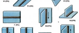
- Welding position (horizontal, vertical, ceiling, etc.)
- Welding angle
Basics
There is such a thing - welding mode. This is a certain number of parameters that are applied during welding. They depend on the situation in which welding occurs.
There are several basic settings that a welder must know. You need to be able to find them, which is what we will do next. These three settings are the speed, which is determined using the following parameters: current and arc voltage.
The quality of the connection depends on whether the settings are correct. It also affects what size the seam will be and how long it will remain strong.
Therefore, you need to calculate them correctly so that the connection can last longer.
We have calculated a table of indicators for different situations, which you can use at the beginning of your work. Professionals themselves must be able to read all these characteristics in order for the seam to be of high quality.
Therefore, you can use it at the beginning of your journey, but gradually get used to doing the calculations yourself. To do this, we recommend learning the necessary formulas.
Welding calculation
To understand the essence, it would be nice to learn how to calculate the welding mode. We will teach you how to calculate manual arc welding modes, since this article is dedicated specifically to MAW. Naturally, the calculation for semi-automatic welding or any other method will be different. But within the framework of one article it is impossible to disclose all methods of calculation. So let's focus on RDS.
Welding current
The strength of the welding current is one of the most important parameters. After all, the higher the current, the faster the metal heats up and melts. And a high melting rate is not always beneficial, but we will talk about this later. Also, with a high current strength, overheating of the electrode and the part may occur, and burns will appear.
Afraid of making such mistakes, beginners often simply set the current to the minimum value, thereby complicating their task. As a result, they end up with unwelded seams and unstable combustion of the welding arc. In the worst case, the welding is simply interrupted as the arc goes out.
If you are a beginner welder, you can use the table below.
And for all practicing craftsmen, we suggest using the following formula for calculating welding current:
where K is the coefficient, dE is the diameter of the electrode, in millimeters.
The coefficient (“K”) depends on the diameter of the electrode (“dE”). To find out the coefficient, see the table below:
In addition to strength, it is important to correctly set the polarity and type of current. It is important to take into account the following features: if you set reverse polarity, the welding depth will increase by about 30-40%. And vice versa if you use straight polarity. The same thing happens when working with direct current, the penetration depth increases by about 10-15%. And with alternating current, on the contrary, it decreases.
Most experienced welders set the polarity and type of current at their own discretion. They observe the burning of the arc and its stability. And based on this, these values are already selected.
Welding speed
Calculation of welding speed does not have to be done using formulas. You can refer to regulatory documents, GOSTs. They specify the welding speed for each type of metal. You can safely rely on these values. A seam that has no unwelded areas or burns is considered ideal. There should be no influx. It is also believed that the width of a high-quality seam should be 2 times greater than the width of the electrode used.
It is also useful to understand what happens to the metal when the welding speed increases or decreases. If the speed is too high, then the metal simply will not heat up to the required temperature and the seams will not be welded. Which means they are fragile and short-lived. Well, if the speed is too low, then the metal will melt violently and sagging will form. In a word, strive for the golden mean.
Electrode diameter
With the diameter of the electrode, everything is more or less simple. The thicker the metal, the larger the diameter of the electrode. Below is a table with approximate values.
Manual welding
The speed of manual arc welding is chosen by the welder himself, so a lot depends on his qualifications. His choice is influenced by:
- properties of the base metal;
- characteristics of the electrode used;
- position of the seam in space.
The requirement that is imposed on the result of the choice is that it must guarantee a slight elevation of the molten metal located in the weld pool above the edges of the main one. A smooth transition of the liquid metal to the base metal without the occurrence of defects in the form of sagging and undercuts must also be ensured. When high-alloy steels are welded, welding is carried out at high speed in order to prevent overheating.
This parameter depends on the coating of the electrodes used. When using electrodes with a rutile coating, the welding speed is selected in the range of 6-12 m/h, with cellulose-coated electrodes - 14-22 m/h.
From the welding speed table for manual arc welding, you can find the value of this parameter depending on the thickness of the metal material.
Determination of modes and technological coefficients
Ministry of Education and Science of the Russian Federation Federal State Autonomous Educational Institution of Higher Education "NORTH CAUCASUS FEDERAL UNIVERSITY"
Guidelines
for performing laboratory work in the discipline
"Metal structures, including welding"
for bachelor students in the field of "Construction"
08.03.01 “Industrial and civil construction”
Stavropol, 2017
This publication presents methods for performing laboratory work in the discipline “Metal structures, including welding.”
Laboratory work in this discipline includes: determining the characteristics of welding arc power sources; determination of melting, deposition and loss coefficients; determination of deformations in a welded joint; defects and quality control of welded joints of metal structures. Each work contains: goals and content; theoretical justification; equipment and materials; safety instructions; methodology and procedure for performing work; contents of the report; questions for job protection.
The instructions correspond to the program of the discipline “Metal structures, including welding” for bachelor students in the direction of “Construction” 03/08/01 “Industrial and civil construction”
Compiled by: Gavrilova A.I., art. Rev.
Content
Management……………………………………………………………………………….4
1. Laboratory work 1 . Definition of characteristics
welding arc power sources
…………………………………………………….5
2. Laboratory work 2 . Definition of modes and
technological coefficients for manual electric arc
welding
………………………………………………………………………………………………….25
3. Laboratory work 3 . Determination of deformations
welded joints MK
……………………………………………………………………….39
4. Laboratory work 4. Defects and quality control
welded joints MK
…………………………………………………………………………….54
List of recommended literature……………………………………………………….64
Maintaining
Laboratory work in the discipline “Metal structures, including welding” allows students to become more familiar with:
− with the technology of performing welding work on direct and alternating current, the technology of applying butt and fillet welds;
− determine modes and technological coefficients for manual electric arc welding;
− determine the deformation of welded joints of metal structures;
− examine defects and be able to determine the quality of welded joints of metal structures.
Lab 1
Characterization of welding arc power sources
1 Purpose of the work
This work aims to familiarize students with the design of an AC and DC welding station for manual arc welding and determining the characteristics of the welding arc power sources.
for manual arc welding on alternating current
– familiarization with the equipment of the AC welding station;
– design and operation of the welding transformer;
– the principle of current regulation and reading its characteristics;
– welding of two plates end-to-end, overlapping, into a tee;
for manual DC electric arc welding
– familiarization with the equipment of a DC welding station;
– familiarization with the nature of arc burning in direct and reverse polarity;
– removal of static characteristics of a direct current arc with a carbon electrode;
Formed competencies or parts thereof
Knowledge of technology for designing parts and structures in accordance with technical specifications (PC-2), knowledge of testing methods for building structures and products, methods of setting up and conducting experiments according to given methods (PC-14)
2 Theoretical part
2.1 General basic theoretical principles
Welding is the process of permanently joining metal products by locally heating them to a molten or plastic state without or with the use of mechanical force.
When electric arc welding, the edges of the parts being welded, as well as electric
trode are melted by the heat of the electric arc burning between the parts being welded and the electrode. The electrode is a metal rod, which at the same time is a filler material.
Figure 1.1 – Electric arc welding: 1 – parts to be welded; 2 – electrode; 3 – electrode holder; 4 – flexible cable
Metal electrode 2 (Figure 1.1) is fixed in the electrode holder 3 and, using a flexible cable 4, is connected to one of the poles of the current source, and the parts to be welded 1 are connected to the second pole.
The resulting arc is a powerful concentrated heat source with a temperature of 4500 – 7000 °C. The arc melts the electrode and melts the base metal, forming a weld pool on it. The molten metal of the electrode drops into the weld pool, mixes with the molten base metal and forms a weld. The electric arc is powered by direct and alternating current. When welding on direct current, rectifiers and generators are used, when welding on alternating current, transformers are used.
The most common types of welded joints are: butt, lap, T, corner, flanged (Figure 1.2).
Figure 1.2 – Types of welded joints: a
– butt;
b
– overlap;
c
– tee;
g
– angular;
d
– flanged
Butt joint is a welded joint in which parts of products are connected along their end surfaces ( a
).
An lap joint is a welded joint in which the side surfaces of the joined products partially overlap each other ( b
).
T-joint is a connection in which the end of one of the products is connected to the side surface of another ( in
).
Corner connection - a connection in which the welded parts of the products are located at an angle (
).
Flanged connection - a connection in which the ends of the connected parts are flanged ( d
).
According to the degree of reinforcement, normal, weakened and reinforced seams are distinguished (Figure 1.3).
Figure 1.3 – Welds by degree of reinforcement: a
– normal;
b
– weakened;
c
– reinforced
A normal weld is a weld whose geometric (actual) height is equal to the design height ( a
).
A weakened seam is a seam whose geometric height is less than the height of a normal seam ( b
).
Reinforced seam - a seam that has a geometric height ( in
) is greater than the height of the normal seam. Depending on the spatial position, there are five positions of welds: bottom, horizontal, vertical, ceiling and boat.
The bottom seams are located in any direction on the lower horizontal plane.
Horizontal seams - located horizontally on a vertical plane.
Vertical seams - located on the upper horizontal plane in any direction. Manual arc welding modes are determined by the diameter of the electrode, the magnitude of the welding current, arc voltage, and the position of the seam in space.
The diameter of the electrode is selected depending on the thickness of the metal and the type of welded joint. The welding current is determined by the selected electrode diameter. The welding speed must also be taken into account. Welding current can be determined by the formula
I=K de
,
A,
(1.1)
where de
– electrode diameter, mm;
TO
– coefficient taking into account the coating of the electrodes and the properties of the metal being welded (
K
= 40 – 60, for low-carbon steel
K
= 50),
A
/
mm
.
With metal thickness <1.5 dе
The welding current should be reduced by 10 - 15%, with a metal thickness >3
dе
- it should be increased by 10 - 15%.
As the welding speed increases, the current should be increased. Welding of metals with low thermal conductivity, for example, chromium-molybdenum steels, is carried out with a current reduced by 10 - 20% compared to low-carbon steels. The greater the thickness of the metal being welded, the higher the current should be. The dependence of the welding current on the thickness of the parts being welded is presented in Figure 1.4.
Figure 1.4 – Dependence of welding current on the thickness of the parts being welded
To obtain high-quality welding, it is necessary to achieve complete fusion of the base metal with the electrode metal. This is achieved by good melting of the surface of the base metal and obtaining a crater of the proper depth. A crater is a depression formed by an arc in the molten base metal. High-quality welding is obtained with a penetration depth of the base metal of at least 1.5 - 2 mm. The amount of penetration is judged by the type of crater. To determine the depth of the crater, the arc is interrupted and the distance from the surface of the base metal to its bottom is measured. By adding 1 - 2 mm to this value, the penetration depths are determined. With the correct welding current, the weld bead will have edges that smoothly merge with the base metal (Figure 1.5 a
).
Figure 1.5 – Welding quality
The base metal under the roller is welded to a depth of 2–3 mm, so the roller is firmly fused with the base metal; resulting in a high-quality connection.
With a small current, the base metal is melted to a small depth and therefore the molten metal of the electrode is fused with the base metal only in the middle (Figure 1.5 b
). From the edges, drops of metal from the electrode fell onto the unmolten metal, and fusion did not occur in this place; as a result, the edges of the roller have a curved shape with a sharp transition to the base metal, and the seam turns out to be fragile.
With an excessively high current, the crater turns out to be very deep and is not completely filled with the electrode metal, due to which a depression is formed at the edges of the roller, which reduces the thickness of the base metal and, therefore, somewhat weakens the strength of the connection (Figure 1.5 c
).
2.2 Basic theoretical principles of manual electric welding with direct current
The main parameters characterizing welding arcs of various types (open, closed and protected, direct and alternating current, with consumable and non-consumable electrodes) include: voltage Ud,
current
Isv
and length
ld.
The relationship between the voltage on the electrodes and the current passing through the arc is called the static characteristics of the arc.
The static characteristic of the arc is a complex function, depending on the length of the arc, as well as on the material of the electrode and product, the diameter of the electrode, the composition and pressure of the gases filling the arc gap, etc.
The static characteristics of the arc for each given case are obtained experimentally.
The static characteristic of the arc is decreasing, that is, the arc ignition voltage is significantly greater than the operating voltage (Figure 1.6). From the curve in Figure 1.6 it can be seen that the voltage Ud
drops sharply in the initial section of the curve to a certain value with a slight change in current, and later, that is, with a stable welding arc, the current value does not affect the voltage.
The shape of the curve does not change if the arc length is changed. In this case, only the position of the curve in the coordinate system changes, since the voltage on the arc is proportional to the length of the arc. In practice, for a welding arc under normal conditions, ignition voltage U =
(40 – 60) V for direct current and (50 – 70) V for alternating current, and the operating voltage
Ud
linearly depends on
ld
and is expressed by the formula
Ud = a + bld
, where
Ud
is the arc voltage;
ld
– arc length;
a
and
b
are coefficients characterizing various arc burning conditions (electrode material, type of current, polarity),
a
characterizes the voltage drop across the electrodes;
for an open arc a
= (18 – 12) V with steel electrodes and
a
= 35–38 V with carbon electrodes;
b
characterizes the voltage drop per 1 mm of arc length;
for air conditions b =
(2.0–2.5) V,
ld
is determined for manual welding as (
0.5-0,
de,
where
de
is the diameter of the electrode in mm.
For steel electrode in manual welding Ud
= (16 – 28) V.
Figure 1.7 shows a graph of arc voltage versus arc length.
The arc ignition voltage must correspond to the open circuit voltage of the power source, that is, for conventional arc welding with steel electrodes, the external characteristic of the current source must be steeply falling.
Figure 1.8 shows characteristic curves of the external characteristics of various current sources. They cross the I
belonging to an arc with a metal electrode.
The intersection points will characterize Ud
- operating voltage and
Isv -
operating current.
The intersection of these curves with the horizontal axis (abscissa) will indicate the corresponding short circuit currents Ik
.
Thus, if the static characteristic of the arc is falling, then the external characteristic of the current source should be more steeply falling.
In this work, the student must become familiar with the nature of the combustion of a “carbon” arc in direct and reverse polarity (Figure 1.9).
With straight polarity, the positive pole is connected to the workpiece being welded, and the negative pole is connected to the electrode.
With reverse polarity, the positive pole is connected to the electrode, and the negative pole is connected to the workpiece being welded. With reverse polarity, the arc becomes unstable, and its appearance changes sharply, the arc column loses its definition, the arc takes on a curved appearance, very easily deviates to the side and goes out.
This difference in the appearance of the arc between the carbon electrode and the workpiece can be used to determine the polarity of the direct current.
Figure 1.6 – Arc characteristic Figure 1.7 – Dependence of
Ud
on
l
Figure 1.8 – Dependences of external characteristics of various current sources
Figure 1.9 – Character of combustion of a “carbon” arc of direct polarity ( a
) and reverse (
b
): 1 – cathode; 2 – arc halo; 3 – anode
3 Equipment and materials
3.1 For manual AC electric arc welding
AC welding station with all necessary equipment (12 stations). Electrodes for welding low carbon steel. Samples of low-carbon steel in the form of plates measuring 100×200×10 mm.
3.2 For manual DC electric arc welding
DC generator – 4 pcs., ammeter, voltmeter, electrode holder, tripod, carbon or graphite electrode, metal ruler, low-carbon steel plate measuring 150x250x20 mm.
4 Safety instructions
Only students who have undergone safety instructions are allowed to perform laboratory work. The laboratory work area should be isolated from the classroom teaching area. The presence of unauthorized persons in the work area is prohibited.
All contact connections must be cleaned and checked for tightness; measuring instruments must be corrected. The use of damaged devices is not permitted.
During breaks in work, as well as after finishing work, all devices must be turned off. It is prohibited to leave electrical appliances connected to the network unattended.
It is prohibited to turn on electric welding equipment without the permission of the training master or teacher.
Do not look into the electric arc with unprotected eyes.
When performing work, use a shield or mask, mittens, and an apron.
After completing welding work, remove the work area.
When carrying out work, there must be mixed lighting, that is, natural and artificial, which ensures illumination of the work area in accordance with the requirements of the standards.
5 Tasks
(
instructions for the order of work
)
5.1 Manual arc welding with alternating current
5.1.1 Description of installation of AC welding station
The electrical circuit of the AC welding station is shown in Figure 1.10.
Figure 1.10 – Electrical diagram of an alternating current welding station: 1 – choke; 2 – screw device; 3 – secondary winding of the transformer; 4 – primary winding of the transformer; 5 – electrode; 6 – product to be welded
The welding machine consists of a transformer and a current regulator (choke - regulator). The welding transformer converts the high mains voltage into a low voltage, but it is sufficient to ignite the arc (60 - 65) V.
The choke limits the short circuit current and regulates the welding current. The primary winding of the transformer 4 is connected to the network, and the inductor 1, consisting of a split core and a coil, is connected to the low voltage secondary winding 3.
The current is regulated by changing the inductive reactance. The moving part of the core is moved using a screw device 2, which ensures a change in the air gap and, consequently, the inductance of the inductor winding.
When the throttle handle is rotated clockwise, the air gap in the reactive coil core increases, the resistance increases and the self-induction current, which is in the opposite direction to the main current, decreases. Rotating the knob counterclockwise reduces the welding current as the gap decreases.
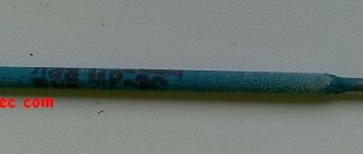
5.1.2 Description - electrodes, ignition of an electric arc, surfacing of bead welds, welding of two plates
The electrodes are metal rods with a diameter of 1 to 12 mm and a length of 250 – 450 mm. In practice, electrodes with a diameter of 2–6 mm are used for welding parts of various thicknesses. Electrodes with a diameter of 2 mm are used to weld parts up to 2 mm thick, with a diameter of 4 – 5 mm – parts with a thickness of 5 – 10 mm, with a diameter of 5 – 8 mm – parts with a thickness of over 10 mm.
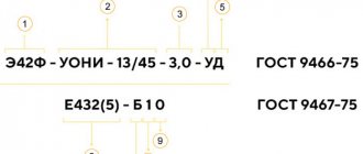
The surface of the electrodes is covered with coating to protect the molten metal bath from contact with oxygen and nitrogen in the air, to increase the stability of the arc and for other purposes. The most popular brands of electrodes for welding low-carbon steels are UONI - 13/45, ANO - 4, SM - 11, OMM - 5, TsM - 7 and others.
Composition of OMM coating – 5: titanium concentrate – 37%, manganese ore – 21%, feldspar – 13%, ferromanganese – 20%, starch – 9%, liquid glass – 30%,
Composition of coating CM – 7: hematite – 33%, granite – 32%, ferromanganese – 30%, starch – 5%, liquid glass – 30%.
Composition of coating UONI - 13: marble - 53%, fluorspar - 19%, quartz sand - 9%, ferromanganese - 2%, ferrosilicon - 3%, ferrotitanium - 15%, liquid glass - 30%.
The thickness of the coating layer ranges from (0.25–1) d
and more, where
d
is the wire diameter in mm.
The arc is ignited in two ways: the electrode touches the workpiece, quickly moves it vertically upward, or the electrode is passed along the surface of the metal and quickly moves it a short distance, exciting the arc. When the electrode is slowly removed from the product, the end of the electrode and the section of metal underneath it become very hot and, with slight pressure on the electrode, they are welded to one another. This phenomenon is called “freezing”.
When the electrode is withdrawn very quickly, the current discharge does not have time to heat the contact point and ionize the arc gap and, as a result, the arc does not ignite.
When the electrode freezes, it is necessary to rock it from side to side, this will allow it to be torn off from the product. Under normal welding conditions, the welder strikes the arc only when changing electrodes, that is, the entire electrode must be melted without interrupting the arc.
With a long arc, the melting of the electrode is accompanied by strong spattering and many large splashes of molten metal appear near the seam. The weld is uneven, with a large number of oxide inclusions, as a result of which the quality of the deposited weld metal deteriorates. When burning, a long arc produces a sharp and loud sound, often interrupted and accompanied by popping sounds.
With a short arc, a small number of small drops of metal will form near the seam, the electrode melts quietly, emitting a uniform sound of one tone, and the depth of penetration of the metal being welded is greater.
A short arc provides higher quality weld metal, largely free of oxygen and nitrogen from the air.
By moving the electrode along the welding line without transverse oscillatory movements, a bead of deposited metal of small width is obtained (a “narrow” bead).
The width of such a roller at normal arc speed is equal to approximately one and a half diameter of the electrode, and the length is the length of the molten electrode.
When moving the electrode along the welding line with transverse vibrations of the end of the electrode, a wide or widened bead is obtained.
Surfacing of bead (butt) welds should be done without rotating the plate. To increase the density of the deposited layer, surfacing beads are used in such a way that each subsequent one overlaps the previous one by 1/3 of its width. Before surfacing the next bead, the previous bead should be cleaned with a wire brush. Only with the permission of the master can a student proceed to welding two plates end-to-end or in a tee. When welding two plates end-to-end, the surfaces to be joined must be prepared: cleaned of rust, oil, paint and other contaminants using wire brushes, make an accurate adjustment of the surfaces to be welded, and in order to avoid warping of the plates, the extreme sections of the surfaces to be joined along the seam line are secured by welding. The technique for applying sutures in T-joints is as follows: the arc is excited on a horizontal surface at point A (Figure 1.12 a ) at a distance of 3 – 4 mm from the weld crater. Figure 1.12 – Technique for suturing T-joints The end of the electrode is then moved to the apex of the joint corner, where the arc is delayed to melt the apex of the corner; then the end of the electrode is moved to a vertical surface by an amount equal to the leg of the seam. When moving the electrode to a vertical surface, it is given a slightly inclined position 2 (Figure 1.12 b ) compared to position 1. Then the end of the electrode is moved down to the top of the corner and onto the horizontal surface at a distance equal to the leg of the seam. In this case, the electrode is given position 3 (Figure 1.12 b ). Next, the end of the electrode is moved along the horizontal surface in the direction of welding and to the crater, again directed to the top of the corner and all movements are repeated again. Welding speed is determined by measuring the length of the weld and the time it takes to deposit it. Before starting laboratory work with manual arc electric welding on alternating current, students become familiar with the design of a welding station on alternating current. 5.1.3 Work order 1. Take the external technical characteristics of the welding machine and write them down in Table 1.1. 2. For the electrodes used, indicate the brand and composition of the coating. Determine current strength I according to formula (1.1) and depending on the thickness of the parts being welded according to Figure 1.4. 3. Under the supervision of a master, learn to light an electric arc. 4. Under the supervision of the master, surfacing bead (butt) welds on the plate in different directions. 5. With the permission of the master, weld two plates end-to-end, overlapping, into a T-joint. 5.2 Manual DC electric arc welding 5.2.1 Installation description The work is performed on the installation of a DC welding station (Figure 1.13). Figure 1.13 – Installation of a DC welding station: 1 – welding current converter (generator); 2 – product; 3 – electrical holder; 4 – electrode; 5 – shunt; 6 – ammeter; 7 – voltmeter Before performing laboratory work on manual DC electric arc welding, students become familiar with the design of a DC welding station, check the switching circuit, and become familiar with the nature of arc burning in direct and reverse polarity. 5.2.2 Work order 1. Install the carbon electrode at a distance of 2 - 3 mm from the workpiece and take the static characteristic of the arc at a welding current of 80 to 200 A. 2. Install the carbon electrode at a distance of 5 - 6 mm from the workpiece and take the static characteristic of the arc at a welding current of 80 to 200 A. 3. Install the carbon electrode at a distance of 7 - 8 mm from the workpiece and take the static characteristic of the arc at a welding current of 80 to 200 A. 4. For each measurement, take the average reading of the oscillating needle of the device. The readings of the voltmeter and ammeter, as well as the calculated values, are placed in Table 1.3. 5. Based on the table data, graphs U=f(I) for different arc lengths. The scale of schedule implementation is recommended 1:1.5 or 1:2. 6. According to the data in Table 1.3, a graph of the dependence Ud= f(ld) and the values of the constants “ 6 Contents of the report 6.1 For manual AC electric arc welding The report must present: 1. Electrical diagram (Figure 1.10) and description of the welding station. 2. Technical characteristics of the welding machine in the form of table 1.1. Table 1.1 – Technical characteristics of the welding machine
3. Description of the electrodes used (brand, coating composition); 4. The results of welding two plates in the form of table 1.2; Table 1.2 – Results of welding two plates
5. Description of the work performed a) ignition of an electric arc; b) surfacing of bead (butt) welds in different directions; c) welding of two plates end-to-end, overlapping and in tees. 6.2 For manual DC electric arc welding The report must present: 1. Diagram of a DC welding station. 2. View of the welding arc in direct and reverse polarity. 3. Table 1.3. 4. Graphs U=f(I) . 5. Graphs of dependence Ud= f(ld) and calculation of the values of the constants “ Table 1.3 – Instrument readings and calculated values for manual DC electric arc welding
7 Test questions and test tasks 1. What is welding? 2. Tell us about how electric arc welding is performed? 3. Name and sketch the types of welded joints. 4. Describe the types of welded joints. 5. Based on the degree of reinforcement, what are the different types of fillet welds? Draw them and describe them. 6. Depending on the location in space, what are the different seams? 7. What determines the diameter of the electrode? How can you determine welding current? 8. How does the amount of current affect the quality of welding? 9. What is an electrode? 10. How is arc ignited? 11. Tell us about the sequence of roller (butt) welds. 12. At what width of the roller and at what angle of inclination of the electrode from the vertical are high-quality seams obtained? 13. Tell us about the technique of suturing in T-joints. 14. List the equipment of the AC welding station. 15. List the equipment of a DC welding station. 16. What is called the static characteristic of the arc? 17. What does the static characteristic of the arc depend on? 18. How is the static characteristic of the arc obtained in each given case? 19. Tell us about the procedure for performing manual arc welding on alternating current. 20. Tell us about the procedure for performing manual arc electric welding on direct current. List of literature recommended for use on this topic: main 1, additional 3,4,5,6. Lab 2 Determination of modes and technological coefficients |
Features for vertical placement
Welding in a vertical position is more difficult compared to the horizontal version. Therefore, the choice of arc welding modes in this case is especially important.
How is the welding current adjusted in a vertical position? The first requirement relates to the arc - it must be short. The volume of the weld pool should not be large. To reduce it, electrodes with a small diameter should be used, and the current should be set 10-15% less than when welding is carried out in a horizontal position at the bottom.
Extra options
Electric arc welding modes include not only basic, but also parameters that complement them. Such arc welding modes also influence the final weld.
Electrode stick out
Electrode extension is the distance from the end of the electrode to the surface of the metal part. It influences the welding process and the size of the resulting seam.
Increasing this parameter reduces the stability of the arc. The metal begins to spatter more strongly. The small overhang makes it difficult to observe the welding process. Spraying occurs on the nozzle.
Electrode coating thickness
Manual arc welding modes include the characteristics of the electrodes, in particular, its coating, namely its thickness. This parameter is regulated by GOST 9466. Optimal coating requires its end size to be in the range of 0.5-2.5 mm. The use of current conductors with such a coating thickness ensures a durable seam that can withstand heavy loads.
Number of passes
The single-pass welding method involves welding in one layer. No oscillatory movements are made. It is used when welding parts of small thickness, when the seam width does not exceed 14-15 mm. At the same time, the magnitude of residual deformations decreases. For butt joints, especially when welding thick elements, several layers are used, and this method is called multi-pass.
A seam made in one pass has a larger pool. The advantages are the high productivity of the process and the cost-effectiveness of the method. Disadvantages include reduced weld ductility and too large heating zone. All seams in multi-pass welding are made with electrodes of the same size.
general information
A welding mode is a set of parameters by setting which we can perform welding. Simply put, this is a set of settings that we apply in a given situation. We devoted a separate article to the topic of choosing a welding mode when working with a semi-automatic machine. Be sure to read it. And we will talk about the basics, and in particular about welding speed.
The main parameters of the welding mode that you need to be able to calculate are welding current, arc voltage and welding speed. In this case, the welding speed cannot be calculated without knowing the current strength and voltage of the welding arc. So in this article we will teach you how to determine all three parameters.
Why are these parameters so important? It’s simple: the quality of the finished seam, its dimensions and other characteristics directly depend on them. If you choose these parameters correctly, you can significantly simplify your work. And the seams will be not only of high quality, but also durable.
Below is a table with recommended welding speeds and more. Such a table will be useful for beginners, but experienced professionals should calculate all the indicators themselves or simply know them by heart. So use this table at the initial stage, and over time, begin to calculate all the indicators yourself.