How does a laser rangefinder work?
The method for accurate non-contact determination of distance with data output to the display is a complex electronic circuit. The design is based on an emitter, a receiver, a time measurement unit and a microprocessor, the combination of which allows us to fully operate the laser rangefinder. The design of the device, in a more detailed analysis of processor boards and modules, has a decent network, whose structure lies far beyond the understanding of the average person. Even radio amateurs who are interested in electronics assemble rangefinders from ready-made elements using soldering and programming.
Essentially speaking, the operating principle of a laser rangefinder is based on the speed of light and the time it takes for the beam to travel to the surface and back. The laser released from the emitter is reflected from the first solid object that comes across the path (even with a large refraction angle), and partially returns to the device, where it is recognized by the receiving module and records the time it takes to cover this distance. Since light travels at a speed of 299,792,458 meters per second or 29.2 centimeters per microsecond (µs), knowing the time it takes to travel, you can easily calculate the length of the path it travels. Thus, the basic formula used by rangefinders is as follows.
The principle presented above applies to pulse rangefinders, which have the widest possible presence on the construction tools market. These devices have decent accuracy with an error of 0.5 to 3 mm, depending on the built-in signal reception sensor, whose processing speed should be lightning fast.
In addition to the pulse method, there is also a phase measurement method, still based on a laser, but radically different in the method of obtaining information. This principle is based on the frequency of the emitted laser, which does not exceed 450 MHz (on average from 10 to 150). Instead of time, the phase difference (outgoing and receiving) is determined here, on the basis of which the distance to the object is calculated. A phase rangefinder takes longer to obtain a value, but the measurement accuracy is superior to a pulse rangefinder.
Sketch for Arduino
#include Adafruit_VL53L0X sensor = Adafruit_VL53L0X(); //Outputs/inputs #define dirPin 3 //Pin for direction of the stepper driver #define stepPin 4 //Pin for steps of the stepper driver #define Enable 5 //Pin for enable the stepper driver //Variables int Value = 1200 ; //Delay value between steps float angle = 0; //Start angle /* —————-Step angle calculation—————- We need 1.5 rotations for 360�. (pully ratio 1.5 : 1) Each 200 steps the motor will make a rotation. We move 2 steps and the we make a measurement. This equals to 360�/(200steps * 1.5) * 2 = 2.4angle/loop -> —————-Step angle calculation—————-*/ float angle_step = 2.4; //So place that value here float maxdist = 400; //I've set the maximum distance around the sensor to only 400mm. Change to any other value. bool loop_starts = false; byte last_PIN_state; void setup() { // Declare pins as output: pinMode(stepPin, OUTPUT); pinMode(dirPin, OUTPUT); pinMode(Enable, OUTPUT); digitalWrite(Enable, LOW); //Place enable to low so the driver is enabeled digitalWrite(dirPin, HIGH); //Place dirPin to HIGH so we spin CW Serial.begin(9600); //Start serial port sensor.begin(); PCICR |= (1 << PCIE0); //enable PCMSK0 scan so we can use interrupts PCMSK0 |= (1 << PCINT0); //Set pin “D8” trigger an interrupt on “any” state change. } void loop() { if (loop_starts) //We reset angle when the magnet is detected on D8 { angle = 0; loop_starts = false; } digitalWrite(stepPin, HIGH); //Make one step delayMicroseconds(Value); //Small delay digitalWrite(stepPin, LOW); //Make another step delayMicroseconds(Value); //Add another delay VL53L0X_RangingMeasurementData_t measure; sensor.rangingTest(&measure, false); // pass in 'true' to get debug data printout! if (measure.RangeStatus != 4) { int r = measure.RangeMilliMeter; if (r > maxdist) //Limit the dsitance to maximum set distance above r = maxdist; Serial.print(angle); //Print the values to serial port Serial.print(“,”); Serial.print(r); Serial.println(“,”); angle = angle + angle_step; //Increase angle value by the angle/loop value set above (in this case 2.4� each loop) } else { //phase failures have incorrect data //Serial.println(" out of range "); } } //This is the magnet detection interruption routine //———————————————- ISR(PCINT0_vect) { if (PINB & B00000001) //We make an AND with the pin state register, We verify if pin 8 is HIGH??? { if (last_PIN_state == 0) { last_PIN_state = 1; } } else if (last_PIN_state == 1) //Now verify if pin 8 is LOW??? -> Magnet was detected { last_PIN_state = 0; loop_starts = true; //If yes, we set loop_starts to true so we reset the angle value } }//End of ISR
Open the Arduino IDE and copy the sketch into it. If, when loading a sketch into the board, a message appears that the “Adafruit_VL53L0X.h” library is missing:
It will need to be installed. To do this, in the “Tools” menu, select “Manage Libraries...” and in the window that appears, find “Adafruit_VL53L0X” (to shorten the list, you can enter “VL53” in the search field:
For VL53L0X, in addition to the library from Adafruit, there is also one from Pololu. It connects in the same way, but the code needs to be changed a little:
#include #include VL53L0X sensor; // Uncomment this line to use long range mode. This // increases the sensitivity of the sensor and extends its // potential range, but increases the likelihood of getting // an inaccurate reading because of reflections from objects // other than the intended target. It works best in dark // conditions. #define LONG_RANGE // Uncomment ONE of these two lines to get // — higher speed at the cost of lower accuracy OR // — higher accuracy at the cost of lower speed #define HIGH_SPEED //#define HIGH_ACCURACY //Outputs/inputs # define dirPin 3 //Pin for direction of the stepper driver #define stepPin 4 //Pin for steps of the stepper driver #define Enable 5 //Pin for enable the stepper driver //Variables int Value = 1200; //Delay value between steps float angle = 0; //Start angle /* —————-Step angle calculation—————- We need 1.5 rotations for 360º. (pully ratio 1.5 : 1) Each 200 steps the motor will make a rotation. We move 2 steps and the we make a measurement. This equals to 360º/(200steps * 1.5) * 2 = 2.4angle/loop -> —————-Step angle calculation—————-*/ float angle_step = 2.4; //So place that value here float maxdist = 400; //I've set the maximum distance around the sensor to only 400mm. Change to any other value. bool loop_starts = false; byte last_PIN_state; void setup() { Serial.begin(115200); Wire.begin(); // Declare pins as output: pinMode(stepPin, OUTPUT); pinMode(dirPin, OUTPUT); pinMode(Enable, OUTPUT); digitalWrite(Enable, LOW); //Place enable to low so the driver is enabeled digitalWrite(dirPin, HIGH); //Place dirPin to HIGH so we spin CW sensor.setTimeout(500); if (!sensor.init()) { Serial.println("Failed to detect and initialize sensor!"); while (1) {} } #if defined LONG_RANGE // lower the return signal rate limit (default is 0.25 MCPS) sensor.setSignalRateLimit(0.1); // increase laser pulse periods (defaults are 14 and 10 PCLKs) sensor.setVcselPulsePeriod(VL53L0X::VcselPeriodPreRange, 18); sensor.setVcselPulsePeriod(VL53L0X::VcselPeriodFinalRange, 14); #endif #if defined HIGH_SPEED // reduce timing budget to 20 ms (default is about 33 ms) sensor.setMeasurementTimingBudget(20000); #elif defined HIGH_ACCURACY // increase timing budget to 200 ms sensor.setMeasurementTimingBudget(200000); #endif PCICR |= (1 << PCIE0); //enable PCMSK0 scan so we can use interrupts PCMSK0 |= (1 << PCINT0); //Set pin “D8” trigger an interrupt on “any” state change. //See interrupt vector below the void loop } void loop() { if (loop_starts) //We reset angle when the magnet is detected on D8 { angle = 0; loop_starts = false; } digitalWrite(stepPin, HIGH); //Make one step delayMicroseconds(Value); //Small delay digitalWrite(stepPin, LOW); //Make another step delayMicroseconds(Value); //Add another delay int r = sensor.readRangeSingleMillimeters(); //Get distance from sensor if (r > maxdist) //Limit the dsitance to maximum set distance above { r = maxdist; } Serial.print(angle); //Print the values to serial port Serial.print(“,”); Serial.print(r); Serial.println(“,”); angle = angle + angle_step; //Increase angle value by the angle/loop value set above (in this case 2.4º each loop) } //This is the magnet detection interruption routine //———————————————- ISR(PCINT0_vect) { if (PINB & B00000001) //We make an AND with the pin state register, We verify if pin 8 is HIGH??? { if (last_PIN_state == 0) { last_PIN_state = 1; } } else if (last_PIN_state == 1) //Now verify if pin 8 is LOW??? -> Magnet was detected { last_PIN_state = 0; loop_starts = true; //If yes, we set loop_starts to true so we reset the angle value } }//End of ISR
In the code for both libraries, at the very beginning of the loop we check whether the Hall sensor has triggered (in the interrupt, the loop_starts variable is set to true) and, if it has triggered, we set the angle variable to 0. If your magnet is not centered under the sensor , assign the appropriate number to this variable.
Next in the code we send a command to the motor driver to rotate the shaft one step, a short pause using delayMicroseconds, then again we rotate the shaft one step and again a pause.
After this, we call the distance measurement function and check whether the sensor has read the correct data. When correct data is received from the sensor, the received distance data is assigned to the variable r. Then a check is made to see if the measured distance is outside the set limits (the maxdist variable) and, if so, the r variable is assigned the value maxdist.
At the end of the cycle, the received data is output to the serial port and the value of the angle_step variable is added to the current value of the angle variable (in this code it is 2.4, i.e. 2.4 degrees). If you have a stepper motor with a different step, you will use the microstepping mode, change the size of the pulleys, or take not two, but one, three, or some other steps, do not forget to recalculate at what angle the sensor will rotate and assign the appropriate value to the angle_step variable.
Laser rangefinder malfunctions
The production of electronic measuring instruments implies the highest precision of assembly with mandatory quality control of each product. They try to isolate the complex design of laser roulettes as much as possible from contact with the external environment and protect them from harsh physical impact. Since the devices are often operated in high-risk environments (in workshops, factories, or storage areas), they are often subject to shocks and strong vibrations that can cause fatal damage to the smallest components of the device.
Read also: Thyristor power regulator circuit for 12 volts
Despite the general operating principle of laser rangefinders, they often have a unique set of components and software. Even if the roots of the malfunction are similar, the design of the part or circuit itself will be individual for each individual model. Problems of a physical nature may be associated with defocusing the laser beam, a broken folding bracket, or deformation of the buttons or case. If desired and with skillful hands, such defects can be eliminated independently.
Repairing electronic components requires much more specific skills, and even special education. Malfunctions of this kind often result in problems with turning on the device, display, signal receiver, and determining the battery charge. The number of defects is proportional to the functionality that a particular rangefinder is equipped with. Repairing a device with your own hands, in the event of faulty electronics, cannot be done without certain knowledge, and it would be better to take it to a specialized service for diagnostics.
Roulette with measuring tape
This is the most affordable tool that almost every master has in his work kit.
It has a simple structure and simple devices that are invisible at first glance. Therefore, not all owners know about them.
Design Features
General form
On the front side of the case there are:
- measuring tape with tip;
- strap;
- tape fixing button.
Laser rangefinder repair
If the damage is mainly of a physical nature, and the electronics are working properly, the device can be restored independently, if you have the desire and ingenuity. First of all, it is necessary to establish the source of the problem based on the existing defect. In this topic, we will look at 2 cases of breakdowns on specific models, and provide recommendations for eliminating them.
The first patient is a Bosch DLE 50 rangefinder with damaged beam focusing due to a fall from the 2nd floor. Instead of a concentrated point, the laser took the form of a flashlight with a blurry spot of light. The measuring capacity of the device has been reduced to 70 cm, and when attempting to measure larger distances, the display shows “Error”. The task is to calibrate the focusing lens in relation to the measuring channel. All elements are located inside the case, so disassembly is necessary.
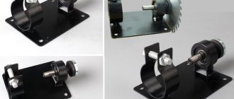
It is likely that the manufacturers of the Bosch DLE 50 model eliminated the need for independent repairs at the design stage. The body of the device has only 3 external threaded connections (2 under the batteries and 1 on the hinged bracket), while the remaining elements are soldered or glued. Of course, in the warranty service, disassembling and assembling such a monolith occurs without problems, but in everyday life this process can cause difficulties. You will need a soldering iron to disconnect the power contacts, and a hot air gun to remove the glued keyboard. All connecting elements are shown in the photographs below, in the order of disassembling the tool.
Having reached the lens and the rod drive unit, you can begin focusing. To do this, we measure a distance from 5 to 15 meters (the more, the better), and at the end of the distance, we place a flat object with a good reflection. We connect the laser to the power source (converter) and begin to gently move the lens until the light beam takes the form of a point. The setup process is quite painstaking and requires patience. When optimal focusing is achieved, the lens should be fixed with hot glue. This way, you can extend the life of a rangefinder with a damaged laser.
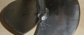
As a second example, consider the breakdown of the hinged bracket of a device of the same brand “Bosch”, but now under the brand “GLM 80”. The plastic element is broken in half and needs to be replaced. The bracket is attached to the tool with a screw, so the process of removing the old part and installing the new part is not difficult. The catch is finding and purchasing a replacement. You can order a new mounting kit, which will cost about 400 rubles (for this model), and will most likely be available in large cities.
An alternative would be to manufacture the part using a 3D printer. In this case, it is necessary to take accurate measurements of all edges of the bracket and create a three-dimensional model in the Tinkercad program or similar. If you don't have modeling experience, you can take the measurement sheet and broken part to your nearest 3D printing service. The quality of such a product is comparable to ordinary flexible plastic, which is quite enough to complete the assigned tasks.
In most cases, repairing laser rangefinders requires an individual approach to each individual failure. An analysis of all possible problems will take the volume of a standard textbook, which cannot be fit into one educational article. If you want to determine the cause or find out how to fix the problem, describe the symptoms of the device in the comments below. Our master will definitely tell you where and how to figure it out. If you are not confident in your skills or patience, then it would be best to contact a specialized service.
Scheme
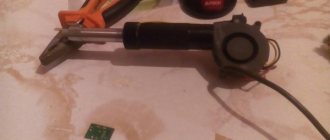
The circuit is simple; some of the parts are soldered on a breadboard.
Through sliding contacts from Arduino, +5V contacts, ground and two I2C interface lines (SCL and SDA) are connected to the VL53L03X sensor. Ground, +5V and pin D8 from Arduino are connected to the Hall sensor. Also, a 10 kOhm resistor is installed between +5V and D8.
5V is supplied to the boost converter. On the board, a construction resistor sets the output voltage to approximately 12V. This 12V from the stabilizer output is connected to the “motor power” terminals of the motor driver module. An electrolytic capacitor is also installed along the 12V line, which is needed for the motor driver to work without failures (it may not be on the board at all, and even when a ceramic or tantalum capacitor is sealed, its capacity is usually not enough). 5V is connected to the “logic power” pins of the motor driver. Do not confuse where the “logic power” and “motor power” pins are, otherwise the driver may fail.
The boards are different, sometimes the plus power supply for the motor is indicated, for example, by the inscription VMOT, and the plus power supply for the logic is designated as VCC. There may be one or more GND pins on the board, in this case it does not matter.
The STEP, DIR and EN pins from the motor driver are connected to the Arduino, and the RESET and SLEEP pins are connected to each other.
On boards with an A4988 motor driver, a trimming resistor is usually soldered, which sets the current limit for the stepper motor. It is highly advisable to set a current limit for stepper motors. If you limit the current too much, the motor under load will either not be able to turn the shaft at all or skip steps. If you set too much current and the power source is able to provide it, the motor will heat up or its windings will simply burn out. It is also a completely unnecessary load on the power supply. When powered by a battery, this will cause it to discharge faster. When powered from USB (power supply, computer or laptop port, etc.), at best there will simply be an extra load, at worst, when the power supply or port is not designed for such a current and there is no protection, this can even lead to failure building a power supply or port.
That's all. The power source is a USB cable connected to the Arduino NANO.
Sensor VL6180X
VL6180X is an optical sensor from STMicroelectronics. It is also called a light (light) and proximity sensor. Its appearance is shown in the following figure.
The VL6180 sensor contains an IR emitter, an ambient light sensor, and a range sensor. It connects to microcontrollers and other electronic devices via the I2C interface. The sensor also has a built-in 2.8 V voltage stabilizer, so it will not be damaged if you connect a voltage of more than 2.8 V to it (well, within reason, of course). The sensor also contains two programmable GPIO pins. The sensor pinout is shown in the following figure.
The VL6180X, unlike other similar sensors, contains an accurate clock for measuring the time of flight of the light flux, which allows it to provide significantly greater measurement accuracy compared to other similar sensors. This also makes it virtually impervious to noise.
The VL6180X sensor is capable of measuring distances up to 25 cm. Therefore, for example, in home use it is perfect for measuring the focal length of a camera or camera. If you need lidar operating over long distances, then in this case you need to use the Vl53l0x sensor instead of the VL6180X sensor, which also has greater measurement accuracy and does not have linearity problems leading to “double images”.