Many are sure that at home it is impossible to make a good soldering iron yourself, which would not only be inferior to factory samples, but even surpass them. And this, of course, is true, but with one caveat: such a task is impossible only for those who do not have a set of simple technological techniques and tricks. In this article, I share my experience and talk in detail about home technologies that make the impossible possible.
Sometimes it's easier to make than to buy
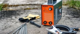
A good electronics engineer should have a wide variety of tools in his arsenal. This also applies to soldering irons. It is impossible to get by with one soldering iron for all cases. There are usually no problems with powerful soldering irons: there is enough of this stuff on sale for every taste. But with their “younger brothers” it’s more difficult. However, it is more correct to talk not about power (it should ideally be adjustable), but about the diameter of the tip and the distance from the tip of the tip to the handle. Power is often talked about as the main criterion, simply for the reason that soldering irons with a thick tip are designed to work with massive parts that have a large thermal capacity - to warm them up, the tool must develop quite a lot of power. And vice versa, for the smallest installation, soldering of SMD components
and microcircuits with small pin pitches require
a miniature soldering iron
with a very
thin tip
.
Such a soldering iron does not need much power, because the thermal capacity of the parts in this case is very small. Moreover, the shorter the distance from the tip of the tip to the handle, the more accurate the movements during soldering. This is especially noticeable under a microscope. But with a long soldering iron, the probability of making a mistake increases significantly, and, for example, “gluing” two closely spaced tracks or pins on a microcircuit, and then spending time eliminating such a defect. But in small installations
this can be very difficult.
That's all you need to make a soldering iron!
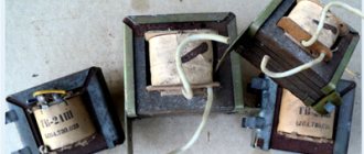
1 - wooden block (material for making a handle); 2 — condensed milk can (mild steel for the body); 3 - silicate glue (liquid glass - a binding component for a heat-resistant composite); 4 - a coil of thin steel wire; 5 - mild steel about 0.5 mm, often called galvanized iron; 6 — wire tuning resistor (source of high-resistance wire for the heater); 7 - a piece of copper winding wire for making a tip; 8 - asbestos cord (fiber for heat-resistant composite). The only thing not shown in the photo is the electrical wire, a small piece of fiberglass, as well as 10 centimeters of any thread and a drop of BF glue. All other materials used are shown in the photo.
Electronics are getting smaller and smaller. Today, a tip with a diameter of even 1 mm seems thick in some cases. In household supply stores you rarely find soldering irons with a power of less than 25 W and a tip diameter of less than 4 - 5 millimeters. For such products, it is better to contact specialized stores. You can also search in online stores. In general, you can find interesting examples. But even with these samples, as a rule, something is wrong. Not a single “spoon of honey” is immune from the “barrel of ointment”. For example, I don’t understand the fashion for stings with a conical working end made of some difficult-to-maintain alloy. Such tips (unless sharpened, and it seems impossible to sharpen them) do not have a working edge and are poorly wetted by solder. But I would like, as the poet said: “And the fingers ask for the pen, the pen for the paper.” Only in our case, instead of a pen, a soldering iron, and instead of paper, you know what. Yes, a soldering iron by its very appearance should inspire inspiration. And what? Technical creativity also requires inspiration. This is also a kind of art.
In general, you can look for a ready-made soldering iron and adapt to its shortcomings, or you can make a soldering iron yourself
, adapting it to your preferences.
Structure and principle of operation
Soldering irons have an extremely simple structure: a copper rod that interacts with a heating element is placed in a kind of tube that acts as a housing. A heat-resistant power wire is connected to the heater. And the whole structure is completed by a handle made of a material with low thermal conductivity.
Under the influence of electric current, a heating element (for example, a nichrome spiral) transfers thermal energy to a copper rod called a tip. The tip, having high thermal conductivity, heats up, which allows soldering.
Knowing how a soldering iron works, you can easily make one yourself. Moreover, this idea can be implemented in different ways, taking into account the needs of a particular situation.
The main difficulties in making a soldering iron
In order for a soldering iron to serve for a long time and flawlessly, it must have the necessary mechanical strength, and its electrical connections must be reliable. In this case, it is necessary that the heater is isolated from the body and tip (even with low-voltage power supply!). The reliability of this insulation is also subject to high demands. In addition, care should be taken to ensure thermal insulation between the heater and the handle.
By themselves, all these conditions are easily met in conventional structures that operate at low temperatures. But we 're talking about a soldering iron
- a product, some parts of which heat up to hundreds of degrees Celsius. The first problem is that many materials that could be used in our product immediately disappear. They are simply not capable of operating at high temperatures. The second problem is the methods of electrical and mechanical connections. Most of the methods available at home for joining parts are unsuitable when working at high temperatures is expected - they are either not applicable to heat-resistant materials, or the resulting connections, at best, will not last long and will collapse. In the past, for example, I could not find a way to connect the heater wire to the electrical cord for a long time. Attempts to directly connect a copper wire with a high-resistance wire constantly ended in copper burning out and the destruction of such a connection. Later, the correct solution was found - an intermediate link made of steel wire ensured high reliability.
What you need to know about a 12 volt soldering iron
A 12V soldering iron has a small tip, which is convenient for soldering the thinnest pins of microcircuits. The NP case does not obscure the full view of radio components on the printed circuit board or circuits of various gadgets. When in contact with a heat-sensitive component, the mini-soldering iron tip will never overheat it.
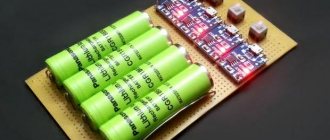
Various batteries are used as power sources for the NP: from a car battery, a screwdriver battery, a block of 18650 batteries to an ordinary 220/12 V adapter.
The low-voltage soldering iron is so easy to manufacture that it will not be difficult for a home radio technician to make it himself. At the same time, you can purchase a reliable instrument at the best price on the radio market.
Materials for making a soldering iron
After first glance at the photo depicting the materials, it may seem that the contents of a trash can have been emptied and neatly laid out in front of the camera. Yes, the soldering iron described in this article is made from such “garbage”.
There was no need to think too hard about the choice of material for the handle. Soldering iron handle
made of wood. This is a readily available material, which is easy to process, quite durable, and has good thermal insulation properties.
Tin from a tin can is used to make a soldering iron body
.
This is a soft sheet of steel that is easy to cut and bend, and at the same time, rolled into a tube, it is strong enough for a miniature soldering iron
. I strongly recommend the condensed milk tin - it does not have polymer coatings, which is important for our case. Tin plate coated on the outside with varnish, like canned fish, or on the inside with something white, like various peas and corn, is not suitable because of this very coating. At high temperatures it will begin to release combustion products that we do not need. I especially want to emphasize that in the store you need to buy not “condensed milk”, but rather whole condensed milk with sugar. I will not describe the difference here - this is not related to the topic, but there is a difference between these products, and the quality of the tin can also be different.
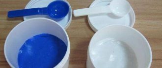
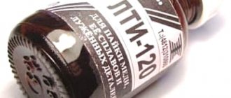
Next on the list is silicate glue.
.
This is a very interesting substance. It does not contain organic matter, is not poisonous, and is not harmful to the skin - you can work without gloves. After drying, it turns into glass - a substance that can easily withstand high temperatures (more than enough for a soldering iron) and at the same time does not conduct electric current. When adding heat-resistant fiber, it forms a composite that also has high mechanical strength. This is what we need as insulation when making a heater
.
In Soviet times, silicate glue could be bought at any bookstore. It was the most popular adhesive for paper and cardboard. But, I must admit, it is not very good for paper. Apparently that’s why it’s not so easy to find it on sale now. Silicate glue has almost completely been replaced by more modern paper adhesives. It’s a pity, because it is indispensable when making a soldering iron
.
But it is still on sale today. The bottle of glue shown in the photo, among other materials, was purchased in 2016 for a symbolic price. Fifteen rubles. I admit, when I saw it at a newsstand located on the territory of a grocery store, I immediately thought about a new homemade soldering iron
, which would bring together all the accumulated best technological solutions.
The seller looked at me strangely, clearly not approving of my choice. I wanted to suggest a higher quality glue. But I assured her that silicate glue
is simply irreplaceable in some cases. She had nothing to object to such a powerful argument, and a profitable deal took place.
I will add that there is a lot of Chinese paper glue on sale now, and, it seems, also silicate. But I haven’t tried to use it, because I really doubt its composition. Most likely, it contains a large percentage of impurities that make the glue more suitable for paper, but absolutely unsuitable for the manufacture of high-temperature composites
.
When heated, these possible impurities can begin to chemically break down, releasing toxic substances. A significant reduction in the strength of the product is also possible. Therefore, when purchasing, it was important for me that this was a domestically produced glue, and very cheap, which means it was just liquid glass
without any additives.
Thin steel wire is used to tie the tin body, which allows you to secure the heater in it, as well as create a “thread” for the handle - a simple but very effective solution. In addition, two pieces of steel wire are required to make the heater leads.
You will need mild steel sheet about 0.5 mm thick. A small rectangle is rolled into a cylinder, which is then inserted into the body from the handle attachment side and provides the necessary strength in this place. Sheet galvanized iron is sold in building materials stores. It's mild steel, like the kind used in tin cans. It is also easy to cut and bend, but it is much thicker than canned material, and therefore parts made from it are stronger. There is no shortage, but stores only sell large sheets. One such sheet is enough for a thousand soldering irons. However, the material is good for many applications. In any case, you need to have it in the household.
For making a heater
a high resistivity alloy wire
will also be required .
You can obtain such wire in different ways. In the described case, the wire was taken from a wire-wound tuning resistor, which was once soldered from a domestically produced color TV. To level it, the wire can be pulled along the edge of the table. It is necessary to evaluate the thickness of the wire, its length and resistance. High accuracy is not required in this case. Just keep in mind that very thin wire reduces the reliability of the soldering iron due to the risk of burnout. Thick wire will be more difficult to wind, and the thickness of the product will be increased. with the wire resistance (and, consequently, with the supply voltage of the soldering iron
) - it is unknown how much of it will go to the heater. It’s easier to make an approximate version, and when the soldering iron is ready, select the voltage to achieve the required power. But too large errors with the heater resistance will lead to the fact that either a very large current will have to be supplied to the heater, which increases the requirements for wires and electrical connections, or to make a power source with a very “specific” voltage, for example, 50 volts. However, the power supply is from 50 When the resistance of the heater is too high, it is much better and more reliable than when the current is unreasonably high - when it is too low.
For making a sting
Thick winding wire with a diameter of 1 to 2 mm is ideal.
You can set aside a whole coil of such wire as a consumable, and in the future, as it wears out, make new tips. The design of the soldering iron
provides for the possibility
of replacing the tip
. It is inserted into the steel base of the heater and is held in place by friction. So you don’t have to worry about the tip burning out.
Asbestos is a naturally occurring fibrous mineral. Resistance to high temperatures is one of its most valuable qualities. In combination with silicate glue
makes it possible to obtain an excellent composite for
heater insulation
.
As you can see, the materials are mostly readily available. Difficulties may arise with the search for asbestos
. If you can’t find the cord, you can try crushing asbestos cardboard and mixing it with silicate glue to get a paste. It can be used to insulate the heater. But I haven't tried this method. I used a cord, separating more or less even sections from it and winding it around the insulated surface. Then it was impregnated with silicate glue. You could try using fiberglass. There is more about this at the end of the article. There was an idea about using gypsum or even clay, but I haven’t tried using these materials either, so I can’t guarantee anything. One way or another, you can find something suitable.
Hair dryer device
A soldering station in the form of a hair dryer is usually used to melt or soften a plastic product, thin metal or tin. It is possible to supply high-temperature air only after it has passed through a very hot spiral. In order to create a soldering gun yourself, you will need to carefully familiarize yourself with its design.
Components of the soldering gun design:
- heater (special housing-tube);
- a vane fan or pump that supplies air flow;
- handles, switch, temperature sensor.
Sometimes you can also use special nozzles that allow you to change the flow of the jet.
Control circuit
Let's consider a circuit diagram for controlling a hair dryer, which is powered from a single source. This fact greatly simplifies the operation of the device.
The main element of this circuit is a parametric type stabilizer, which is assembled on transistor VT1, zener diodes D5, D6, D7 and resistance R1. This device guarantees the stability of the soldering gun voltage, while the source voltage may change due to air flow adjustments.
In order to change the fan speed, switch SA1 is used, which has two positions - 8V and 12V.
Zener diode D8 and fuse FU1 provide protection against extreme voltages. When the voltage rises to 15 volts, the diode opens and the fuse blows.
Let's figure out why it is best to use a parametric stabilizer in this design. When using alternating current, voltage peaks can reach extreme values. This will damage the microcircuit. It's quite easy to give an example. At a voltage of 30 Volts (alternating current), the peak will be:
The bee doesn’t have a pity, or What a good sting should be
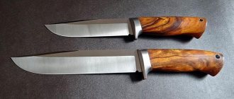
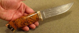
If theater begins with a hanger, then a soldering iron begins with a tip. Both ease of use and the result obtained largely depend on the quality of the tip. Making a soldering iron
It's also wise to start with choosing a tip.
But what kind of a good sting
?
Here I would like to recommend a short article about the basic secrets of good soldering. It talks about the physics of the process, how wetting, capillary effect and surface tension solve most of the problem for us. This information is very useful for beginners and will not hurt those who are continuing.
But, returning to the topic of a good sting, we will have to remember physics again. Now from the field of thermodynamics. Don't be alarmed - there will be no formulas. We are talking about what shape the working surface of the tip
.
We had to touch on this topic because manufacturers of soldering irons have a unique understanding of the optimal shape of the working surface and supply their products with tips sharpened to a cone. As a rule, imported soldering irons suffer from this. I can’t say the same about domestic ones yet. I think this is a marketing ploy among foreigners, aimed at the mass amateur, for whom the sharp end of a conical tip
is associated with high soldering precision.
But let's figure it out. A cone, in principle, can be beneficial and effective, but only from the point of view of heat transfer along the entire length of the tip - this is when the entire tip is conical
(at least its outer part).
At the same time, the cone-shaped working surface is extremely inconvenient and ineffective. That is, if you have a cylindrical tip
and a conical working end, this is bad and pointless. Why is this so, and what does physics and its thermodynamics have to do with it?
As is known, heat transfer proceeds faster, the larger the surface area of contact of interacting bodies. In our case, this is a tip and a part. This means that, ideally, the surfaces should either be both flat, or each convexity should have its own “convexity,” and vice versa. Conical working surface of the tip
thus optimized for soldering “pits” and various kinds of “holes”, which is not so in demand in practice.
But working with a plane, for example, tinning a contact pad
on a board, will be much more difficult with a cone than with a flat edge.
Practice shows that it is the flat edge that is the most universal working surface, which means that the tip can be sharpened as you like, but so that there is at least one flat edge. In this case, it is not at all necessary to turn the sting into a “shovel”. Even the smallest flat surface at the end of the tip provides a noticeable gain in ease of use of the tool. For thin tips
(1-2 mm), we can recommend two classic forms of sharpening: wedge-shaped - with two flat edges, and oblique cut - with one flat edge. Of course, any variations are possible (there are an indescribable number of them) for reasons of convenience for a particular case, but do not lose the working edge by getting carried away with sharpening.
We figured out the shape of the working surface. And now it may not even be clear why I am picking on manufacturers of soldering irons with conically sharpened tips, if the tip can be resharpened. Yes, the fact of the matter is that not every tip requires sharpening. The tips I criticized are often short in length and not made of copper. It seems like this is some supposedly wear-resistant non-burnable alloy. Maybe with some kind of coating. There is no point in sharpening also because this alloy is poorly wetted by solder. That is, tin
such a sting is very difficult even with the use of the best fluxes. And after prolonged effort, when everything seems to have worked out, the tip is tinned, soon the solder on the surface of the tip again becomes uneven and begins to gradually gather into droplets. Maybe that’s why the sting doesn’t burn because it can’t be used. It’s like that joke: to prevent toys from breaking, don’t give them to children. Why then use such metal for a sting, if even an ordinary iron nail is more suitable for this role? But maybe I just don’t understand something about the newfangled stings. I would be grateful if someone could tell me what I'm doing wrong, if so.
I can’t recommend anything better than ordinary copper for a sting. Some copper alloys are also good. I'm in my soldering iron
I used a piece of thick winding wire for the tip.
At first the tip
was made with some extra length, then I shortened it slightly. This is due to the fact that for a tip with a constant cross-sectional area (not a cone), there is a maximum permissible length for a given diameter. Approximately (I do not pretend to be mathematically accurate!) the length of the outer part of the cylindrical tip (from the tip to the edge of the heater) can reach ten diameters. Exceeding this limit reduces the heat transfer efficiency of the tip, resulting in the ability to solder only small parts even with a powerful heater.
And now, when there is complete clarity about what a good sting
, you can describe the process
of making a soldering iron
.
In my description I do not give exact dimensions, since this makes no sense. Exactly copying a product in compliance with all dimensions is an extremely labor-intensive task. The technology I propose is based on the fact that the dimensions of subsequent parts depend on the finished parts and are adjusted to the exact dimensions of the finished parts, where necessary. In cases where dimensions are not of fundamental importance, they are selected “by eye”. And the first dimensions that I had to decide on were the diameter and length of the part of the tip that goes into the heater
.
I prepared a piece of thick winding wire for the future tip, aligning one end of it. I have not removed the enamel coating yet, so that there is some margin in diameter. There were fears (possibly unfounded) that I would not be able to insert the tip
due to the “too precise” size match. Thus, the diameter of the enameled copper wire became the internal diameter of the base of the future heater. I chose the length of the heater intuitively.
Heater base
The base of the heater is made of tin from a tin can. It is a steel tube into which the sting blank enters with some friction. The tube is obtained by rolling a tin rectangle on a mandrel of suitable diameter. To roll up the sheet metal, you can use a vice and pliers. The dimensions of the rectangle are selected so that the edges of the metal sheet meet without overlapping and do not form a gap. One end of the tube (from the side where the tip enters) expands in the form of a bell. To do this, several cuts are made on the edge of the tin blank before rolling it into a tube. On the contrary, the opposite end of the tube is kneaded so that the inserted tip
had a stop in
the heater
. When pinching the end of the tube, do not forget to insert the tip blank first, otherwise the tube will be deformed more than necessary, and the tip may not be fully inserted in the future.
If you want the soldering iron
If there was an additional wire connected to the sting, for example, for antistatic purposes, then it makes sense at this stage to insert a piece of steel wire into the crimped end of the heater base to a depth equal to the length of the crimped part of the tube.
In the future, you can solder an antistatic wire to this steel wire and connect it to a bracelet on your wrist (preferably through a 1 MOhm resistor). This way, electronic components that are sensitive to static electricity will be safe. It is not necessary to use grounding for this purpose. But keep in mind that if you connect the antistatic wire to ground and do not connect it to your body, then there will be no effect of antistatic protection
- the potentials between you and the ground will not be equalized. And remember that you can connect yourself to ground ONLY THROUGH A RESISTOR of at least 1 MOhm. There are no options. The equipment is grounded, of course, directly, without any resistors.
Finished heater base
must be covered with durable
heat-resistant insulation
.
For this I used asbestos cord
and
silicate glue
. I separated small bundles of fibers from the cord, removed defects in the form of solid particles, and wound them onto a tin tube in as thin a layer as possible, but without gaps. At the same time, the fibers were impregnated with glue. The tip blank was inserted to prevent glue from flowing into the cavity of the tube. Periodically, I pulled the tip blank out of the tube to prevent it from sticking to the base of the heater.
Before winding high-resistance wire, the insulation layer must dry thoroughly.
Remaking an old soldering iron
An old 220 V soldering iron can be converted to a 12 V NP. To do this proceed as follows:
- Unscrew two screws on the body and remove the tip.
- Remove the handle and separate the twists of the power cord and heater wires.
- Using a knife, pry off the bushing and remove the heating element from the housing.
- Remove the thermal fabric, mica shells, and wind up two layers of nichrome thread. Subsequently, only the heating wire of the top layer will be needed.
- At the front end of the tube (from the tip side), a copper wire is secured with a ring, one end of which is twisted with a nichrome thread.
- A heating coil is wound around the tube, the end of which is twisted with another piece of copper wire.
- The spiral is covered with a mica shell.
- Bend the front copper wire to the tube and cover the rod with a second layer of mica.
- The leads of the copper wires are connected to the power cord.
- The heating element is wrapped in thermal cloth and inserted into the soldering iron casing.
- The tip is inserted and secured with screws.
- On the other hand, put on the handle.
- The cord plug can be removed. Instead, connect a contact connector corresponding to the power supply sockets.
- The 12 volt soldering iron is ready for use.
Making a heater
Heater wire winding process
does not require any special comments. The photo shows how it was done. The first layer is wound from the rear end of the heater base towards the tip.
It is advisable to lay the turns closer to each other, but not too closely, leaving some distance between them so that the likelihood of short-circuited turns remains minimal. The wire, of course, tries to unwind, but you need to somehow prevent it from doing this. Various tricks are suitable for this.
The first layer of coils is covered with insulation in the same way that the base of the heater was covered. After this, the glue is dried again.
The second layer of turns is wound in the opposite direction - from the tip to the rear end of the heater. Once again, the product is covered with insulation and then thoroughly dried.
If, after the next drying of the insulating composite, significant irregularities are visible, they can be smoothed out with a file or sandpaper. It is useful to do this at each stage, thereby maintaining the cylindrical shape of the heater. In this case, you need to ensure that the insulated surface is not exposed. It is better to scrape the dried composite in the fresh air so as not to spread asbestos dust indoors - they say it is not very useful.
Making heater leads
Direct connection of high resistance wire
and
an electrical cord
supplying power to the heater is not a good technical solution.
If this is done near a heater, the joint will be exposed to high temperatures and will quickly collapse. If this is done inside the handle, where it is cooler, then such a connection, although it will last longer, will also collapse. Moreover, the ends of the high-resistance wire will generate unnecessary heat all the way from the heater to the handle. A reasonable solution is to use an intermediate link made of metal that can withstand high temperatures well and, at the same time, has a low resistivity
. Steel is quite suitable for this role.
For making heater leads
I used two pieces of steel wire in my soldering iron. Considering the high temperature, there is no point in soldering here. The connection is made by twisting one wire onto another. But simple twisting is unreliable. To increase reliability, the connections are crimped with tin tubes, which are made in exactly the same way as the base of the heater - by folding a tin rectangle on a mandrel. But here it is better that the edges of the tin strip meet with some overlap. You can use a needle of suitable thickness as a mandrel. With the correct diameter, the finished tube is put on the joint with some friction. Next, each inserted tube is compressed with pliers and slightly flattened, which ultimately ensures high strength of the connection.
The next step is to isolate the findings. The same materials were used for this - asbestos
and
silicate glue
.
At this stage, it is necessary to exclude any possibility of shorting the heater terminals. This is especially true for joints crimped with tin tubes, since these places are much thicker. steel leads
are coated with an insulating composite up to the point where they meet the copper conductors
of the electrical cord
inside the handle.
Next, the finished heater was thoroughly dried. Dry the soldering iron heater
you can simply put it somewhere and forget about its existence for a long time, or apply a small voltage to its terminals to speed up drying. In the second case, it should be remembered that too high a voltage can cause the temperature to rise to such a value at which the silicate glue begins to boil. Until the glue dries completely, you cannot bring the temperature to the boiling point, otherwise this will lead to various swelling and deformation of the product, which can ultimately ruin the entire work. Irregularities on the surface of the dried heater can be eliminated using a file and sandpaper, bringing the product into a cylindrical shape.
By measuring the resistance between the base of the heater and its terminals, you can to some extent judge the completion of drying. In my case, this resistance after thoroughly drying the heater was 20-30 kOhm. By this time there was no longer any danger of the glue boiling over. After warming up the soldering iron
in operating mode, this resistance increased to several megaohms.
Manufacturing the body and installing the heater
The body is made of tin from a tin can. The workpiece is a rectangle, the width of which depends on the diameter of the heater. In my case, the dimensions of the workpiece were 20.5 X 80 mm. Rows of holes are made to reduce heat transfer
along the body into the handle.
The workpiece is rolled into a tube on a mandrel of suitable diameter. A heater is inserted into the resulting tube.
The heater is fixed
in the housing by tightly wrapping the housing in the heater area with steel wire. In order for the ends of the wire to meet, I first bent it at a right angle, stepping back a few centimeters from the beginning, and laid this section of wire in the gap between the edges of the body plate bent into a tube in the direction from the future handle to the tip. Then he tightly wound the wire turn to turn in the direction from the tip to the handle and connected the ends by twisting. The twist was tucked into the slot of the case.
From a resistor
You can make a miniature homemade soldering iron for 12 volts using permanent metal film resistors, for example, MLT-2 with a power of 2 W.
They work even with an overload of up to 6-10 times, so it is not difficult to achieve power output of up to 12-20 W from them. But a significant part of it will be wasted on heat exchange with air due to the relatively large surface area of the resistor. For manufacturing you will need a resistor with a nominal value of 24-27 Ohms.
One of its fairly thick leads will serve as a soldering iron tip, the second – as a contact for the power wire.
The resistor body near the tip contact must be cleaned of paint and tightly wrapped with a second supply wire. The working circuit of the soldering iron is ready.
All that remains is to place it in a case that will be convenient to use. To do this, the resistor is wrapped in a heat-resistant heat-insulating material, for example, fiberglass, and placed in a plastic tube of a suitable diameter.
Design features on the handle side
The opposite side of the body, connected to the handle, is reinforced in the same way as the side of the heater - by wrapping it with steel wire. At the same time, this winding also plays the role of a thread, providing the possibility of a simple and high-quality connection between the body and the handle
. I, of course, did not cut a thread in the hole of the handle, but only adjusted the diameter of the hole with a round file to the size where the wire “thread” can be screwed into the handle without excessive effort, but at the same time, firmly.
The wire is wound as tightly as possible to make the body durable. But if on the side of the tip under the thin sheet there is a heater hard as a stone, then the side of the handle would be crushed during the wrapping process if I had not installed an additional part - a reinforcing sleeve. The bushing (see photo) is made by bending a rectangle cut from a steel sheet (galvanized iron).
Inside the soldering iron handle
the temperature is no longer as high as near the heater, so the choice of materials and methods of connecting parts is much wider here.
Materials that are less heat-resistant can be used, and electrical connections can be made using soldering. To make the connection of the heater leads
to
the electrical cord
rigid, I inserted a rectangle of fiberglass into the body of the future soldering iron between the leads sticking out of it. The width of the rectangle is chosen so that it is inserted with considerable effort and does not dangle after installation.
Connecting a 12 V soldering iron
Soldering iron EPSN
It is very important that the connection of the power cord to the power source is as safe as possible. To do this, use various connectors that fit tightly into the sockets of the power units.
Depending on the design of the NP, the required characteristics of the supply current, and the types of power sources, plugs, clamps, clamps, pin lugs or plugs for a car cigarette lighter are used.
Since mini-soldering irons do not have automatic heating control, they must be turned off periodically. Otherwise, the device will malfunction. To quickly turn off the soldering iron, the power connectors should be convenient in this regard.
Making a pen
Soldering iron handle
planed with a knife from a wooden block without the use of machines. But first a hole was drilled in the block. If you first plan the cylinder and then drill a hole in it, then without using a machine it will be very difficult to get the hole exactly in the center. It is much easier to first drill and then smoothly plan the workpiece around the existing hole. The finished handle is sanded.
The diameter of the hole in the handle on the side connected to the body is slightly increased to a certain depth. This is done so that the actual contact between the metal body (carrying the unwanted heat flow from the heater) and the handle occurs a little deeper inside the handle. Thus, while maintaining a small distance from the tip to the handle
Handle heating
is reduced .
Induction
An induction soldering iron is distinguished by its heating principle. Distinctive features of such devices:
- The principle of heating without contact with the rod: electromagnetic fields arise due to the flow of current to the wire coil.
- High heating capabilities.
- Special structure: the rod is inserted into the coils themselves, and not into the casing with the thread. Fiberglass is optional.
Additionally! This classification also includes nichrome, ceramic, and pulse soldering irons.
Expert opinion
It-Technology, Electrical power and electronics specialist
Ask questions to the “Specialist for modernization of energy generation systems”
Do-it-yourself powerful soldering iron from a cigarette lighter for a car To seal the back side of a plastic pipe, where the socket for the plug will be installed, you need to cut a circle from a plastic plug. Ask, I'm in touch!
Connecting the electrical cord
As an electrical cord
I used a cord from a telephone handset.
I agree, this is not the best option for a soldering iron - such a wire is designed for currents of a maximum of several tens of milliamps, which is not enough for a soldering iron
. It won't burn out - it will create unnecessary resistance. But I wanted to have a cord twisted into a “spring”. Yes, in addition, a wire turned up that had a defect in one of the connectors, and it was no longer suitable for its intended purpose. The photo shows how the connection is made. The ends of the cord conductors are freed from insulation. The cord is fixed by winding it with threads to the fiberglass protruding from the body. The place where the threads are attached is covered with BF glue (marked with number 2 in the photo). The connection of the heater leads to the copper conductors of the cord is made by soldering (marked with numbers 1 in the photo).
Basic properties
Pulse soldering iron gun
The main properties of a micro-soldering iron include:
- small sizes, ensuring the accessibility of the soldering iron in inconvenient places on printed circuit boards;
- economical energy consumption;
- the ability to use various batteries as a power source;
- universal power supply, both from alternating and direct current;
- the simplicity of the design of the NP allows it to be repaired.
Completing the soldering iron assembly
Of course, before I attached the cord, I put a handle on it. Next, all that remained was to screw in the body of the soldering iron
into the handle using his improvised carving.
After connecting the handle to the body
the place where the cord exits the handle is additionally reinforced so that the cord does not dangle in the handle and extraneous forces are not transferred to the connections located inside.
Finally the sting is inserted
,
soldering iron has been tested
. Everything worked out as it should. A soldering iron that is properly assembled from suitable materials does not smoke or emit odors. A little later I varnished the handle.
If the tip enters the heater
too loose, you can wrap it with a strip of aluminum foil.
It is better not to use copper foil, so as not to get scale in its place over time, making it difficult to remove the worn tip. After testing, I shortened the tip a little, bringing its outer length to about ten diameters. Reducing the length of the tip expands the capabilities of the soldering iron and allows even a thin tip
to perform not the smallest work.
How to repair a soldering iron, device, diagram, winding calculation
- The main element is a transformer, resistor, lighter and other things on which the device will work.
- The tip is a copper wire with a cross-section of 2.5 mm or more.
- Fiberglass (asbestos) material is an insulating agent. It is found in electrical devices, in ordinary lamps. You can also use silicate glue together with talc.
- Nichrome thread. It can be taken from an iron, hair dryer and other home heating devices.
- The heater body is a thin tube made of refractory metal.
- Handle: any ready-made holder, for example, made of wood or heat-resistant plastic, can be used. Pieces of PCB will do.