Very often, welding work requires an inverter, thanks to which you can get high-quality seams and not take risks when working with gas welding. But purchasing such a device is associated with significant costs, so you can try making a welding machine from a computer power supply. For this you need not only spare parts, wires and a soldering iron. But also skills in electrical engineering, without which you can burn electrical wiring or get an electric shock.
The main components of the welding machine design.
{advertisement1}
Assembly, installation and subsequent testing can only be carried out if you have experience in rewinding transformers, assembling circuits and creating electrical devices with your own hands. If such knowledge is absent, then it is best to purchase a ready-made inverter and not expose yourself or others to danger.
Basic installation tools
Classification of welding transformers.
If you have experience and knowledge in the field of electrical engineering, then you can explore several options on how to make a welding machine from a computer unit. Basic tools that will be needed for all types of assembly:
- soldering iron or soldering station;
- tester;
- multimeter;
- electrical insulating tape;
- solder;
- screwdrivers with different tips;
- pliers;
- screws;
- screwdriver or drill;
- crocodiles;
- wires of the required cross-section.
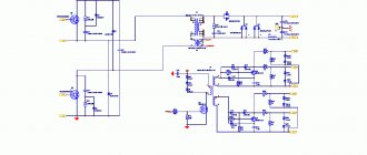
To recreate the circuit of the welding machine, you will need all the spare parts indicated in the circuit, getinaks and solutions for transferring the printed circuit board to the workpiece.
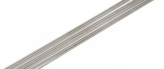
To make your work easier, you can purchase an electrode holder and welding cables at the store. You can do it yourself by selecting wires of the appropriate cross-section and soldering crocodiles to them, remembering to observe the polarity.
Welding inverter circuit.
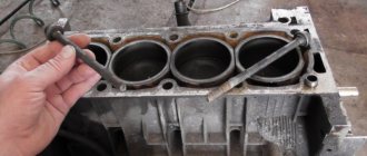
If you have a non-working computer system unit, then you need to remove the main battery from it and prepare it for dismantling. Sometimes, to create a powerful welding machine, they even use the system unit itself, installing wheels on it at the bottom and increasing the number of ventilation holes. The advantage of computer cases is that they are lightweight, easy to cool and already have ventilation.
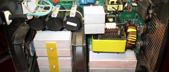
The welding machine will require disassembling the power supply.
The main things that can be used from it are the fan, the housing itself and some spare parts. But it all depends on the modes in which the cooling operates. The fan must be checked for functionality and tested in several modes. It is advisable to install another one of the same or more powerful so that the welding machine does not overheat. To monitor the temperature of the inverter, you need to install a thermocouple.
But first you need to take care of the handle, which will make the welding machine from a computer power supply convenient to use. To do this, you need to remove all the spare parts from the power supply and attach a handle selected for size and convenience to the upper end. You need to drill holes in the power supply and secure it with screws, which must be correctly selected in length (too long ones will interfere with the internal circuit, which is unacceptable).
The welding machine must have very good cooling, so several additional holes need to be drilled in the power supply housing.
The duration of operation of a homemade inverter will depend on the quality of ventilation.
Why assemble a homemade device?
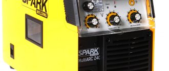
Many craftsmen may ask the question: “Is it even worth assembling a device with your own hands from a computer power supply, if in a store you can easily buy a cheap inverter costing $50 and not have to worry?” Fair. But not everything is as obvious as it seems at first glance.
A purchased inverter welding unit that costs $50 is quite an adventure. These devices are not suitable even for occasional use, let alone constant welding. Let's say, throughout the entire summer season (and this is the period from April to November!). How to solve this problem? Buy the device for at least $100. But in this case, there is no question of saving. For many compatriots, $100 is half their salary, if not more.
Selecting a transformer for a welding machine
Transformer diagram for a welding machine.
For a circuit that will allow you to make a welding machine from a computer power supply, you will need 3 transformers. They can be purchased based on the names - E20, Kx20x10x5 and ETD 59. But it will be easier to wind them yourself, focusing on the number of turns and other information indicated in the diagram. A current transformer K17x6x5 is also required.
Regarding the manufacture of transformers, you only need an enamel wire, and a new f1.5 or f2. There is no way to do without winding on getinax coils, crimping them with wooden blocks and impregnating them with epoxy resin.
To assemble a device from a computer power supply, you can use a transformer from a microwave oven. Since the voltage on the secondary winding is about 2 kV, it is necessary to reduce the number of turns. To do this, you need to make an additional calculation, which can be done using a special online electrician calculator or find a book on electrical engineering with the corresponding section. But for the sake of such savings, changes will have to be made to the existing scheme.
Advantages of a welding machine from a computer power supply
A homemade welding machine will be small and light. It is perfect for home welding; it is convenient to weld with two or three electrodes, without experiencing problems with “flashing lights” and without worrying about the electrical wiring. The power supply for such a welding machine can be any household outlet, and during operation such a device will practically not spark.
By making a welding inverter with your own hands, you can significantly save on purchasing a new device, but this approach will require a significant investment of both effort and time. After assembling the finished sample, you can try to make your own changes to the welding machine from the computer unit and its circuit, to make lightweight models of greater power. And by making such devices for friends to order, you can provide yourself with a good additional income.
Recommendations for installing other parts of the circuit
P series connection diagram With current transformer.
Due to the fact that this circuit has already been repeatedly used to assemble a welder that has become a replacement for an inverter, there are some comments about it. It is recommended to replace 15tb60 diodes with 25tv60, and it is best to install 150ebu02 diodes in groups of 2.
To save money on the radiator, you can take the PIV and cut it into 3 parts. It is mandatory to use a converter - a single-cycle forward-flow quasi-bridge. Or, more simply, an “oblique bridge”, without which not a single inverter can be assembled. It’s better not to skimp on this spare part and buy a good quality one, not a used one.
Keys for transistors irg4pc50ud and irg4bac50w, as well as printed circuit boards for the generator and processor must first be downloaded on the Internet in order to easily recreate the circuit.
When working, be sure to use a multimeter and tester so that the circuit can be assembled quickly and without errors. You cannot connect it to the network immediately after assembly without preliminary testing, so as not to burn the main components.
https://moyakovka.ru/youtu.be/DdKhWxEGy_U
{reklama2} Installation of transistors and output diodes on radiators should be carried out without additional gaskets. Overheating protection must be set at a temperature of 70°C, which is carried out using a thermocouple.
Inverter assembly sequence
When preparing for the final assembly of the inverter, it is necessary to ensure that there is a temperature sensor designed to operate when heated from 70 to 75 ° C. In addition, you need to take care of the sockets for the power cable and the electrode holder with wires with a cross-section of 35 mm2 or more, for efficient supply of welding arc current. Then, having prepared all the necessary elements, we begin installation in the following sequence:
- we position the fan and cooling radiators so as to ensure the most efficient air flow, and provide reliable fastening;
- securely fasten the transformer and capacitor board;
- install the control circuit board and related parts;
- we install an anti-stick and hot start device;
- we check for short circuits the contacts through which the circuit components are powered;
- We carry out final wiring and installation of fuses and thermoelements;
- We carry out the final adjustment using a multimeter and an oscilloscope, taking into account the calculated parameters;
- We set the required welding current and carry out trial work.
Self-installation is a very responsible job, so it is very important to follow safety rules, both during installation and during the process of checking the assembled inverter.
Installing a soldered chip into the case
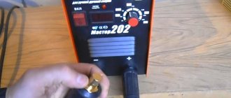
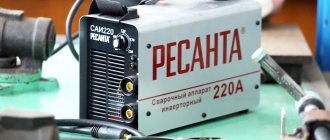
After all the necessary parts have been manufactured and assembled into a single whole, you need to place them in the housing and make the correct wiring. The power supply on/off switch is used as a switch for the future device. On the front panel you need to provide a current regulator and contact holders for connecting welding wires. The housing must be carefully and firmly secured. The end result should be a product that looks something like this.
Such production of a welding machine will allow significant savings, but will require a lot of effort. But after successfully assembling the first inverter, it will be possible to make changes to the circuit, invent your own models (more powerful or lighter) and make such custom-made devices familiar. And this can be a great way to earn extra money.
Voltage converter design
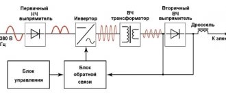
Let's consider the design of a conventional step-up voltage converter from 12 to 220. The operating principle for all modern inverters will be the same. The high-frequency PWM controller sets the operating mode, frequency and amplitude. The power part is made of powerful transistors, the heat from which is transferred to the device body.
At the input of the converter from 12 to 220 there is a fuse that protects the car battery from short circuits. A thermal sensor is attached next to the transistors, which monitors their heating. If the 12v-220v inverter overheats, an active cooling system consisting of one or more fans is turned on. In budget models, the fan can work constantly, and not just under high load.
Power transistors at the output
Power converter circuits
A powerful inverter is mainly used to connect construction power tools during the construction of a summer house or hacienda. A low-power 500-watt voltage converter differs from a powerful 5,000-10,000-watt converter in the number of transformers and power transistors at the output. Therefore, the manufacturing complexity and price are almost the same; transistors are inexpensive. The power is optimally 3000 W, you can connect a drill, grinder and other tools.
I will show several inverter circuits from 12, 24, 36 to 220V. It is not recommended to install these in a passenger car; you can accidentally damage the electrics. The circuit design of DC AC converters 12 to 220 is simple, a master oscillator and a power section. The generator is made on the popular TL494 or analogues.
A large number of booster circuits from 12v to 220v for making with your own hands can be found at the link https://cxema.my1.ru/publ/istochniki_pitanija/preobrazovateli_naprjazhenija/101-4 In total there are about 140 circuits, half of them are boost converters with 12, 24 at 220V. Powers from 50 to 5000 W.
After assembly, you will need to adjust the entire circuit using an oscilloscope; it is advisable to have experience working with high-voltage circuits.
To assemble a powerful 2500 Watt inverter you will need 16 transistors and 4 suitable transformers. The cost of the product will be considerable, comparable to the cost of a similar radio designer. The advantage of such costs will be a pure sine output.
Sergey, hello! I have a question: I have a DC12->AC220 converter for 300W, I power my computer with it. Everything works fine for about 1-2 hours (consumption is approximately 120W). But when the converter lacks energy, it makes a wild squeak and immediately abruptly cuts off the output. At the same time, approximately 11.5 volts remain in the battery. The converter is Chinese, but in appearance it is quite good. The question itself is: why does this happen if there is still a lot of energy in the battery and how to improve this so that the converter sucks out at least half the energy. Ideally, it would also squeak a little before dying.