Legris > Functional fittings 7000 series >
Note: In addition to the 79** series check valves shown further down on this page which are made of plastic + nickel plated brass, we also offer other series check valves such as the 48** series check valves made of stainless steel.
A check valve allows compressed air to pass in one direction, but prevents it from flowing back. The opening pressure for Legris check valves is 0.3 bar - this pressure is enough to lift the diaphragm in the normal direction of flow; The diaphragm will not allow air to pass back.
Legree check valves are distinguished by their reliable operation, including in the presence of strong vibration, as well as their extreme compactness and low weight. The valve can be mounted both at the compressed air inlet into the pneumatic system segment and at the outlet from it.
Each of our check valves is marked with an arrow or symbol indicating the direction of compressed air flow.
In addition to the check valves shown on this page, we also offer stainless steel check valves.
Check valve device
- 7996 - built-in check valve with push-in connections LF 3000
- 7984 - check valve with push-in connections LF 3000, BSPP and M5 threads
- 7985 - check valve with push-in connections LF 3000, BSPT thread
Operating principle of a check valve
Common parameters:
- Maximum operating pressure: 10 bar
- Operating temperature: from 0°C to +70°
Knocking and rattling in the cylinder and piston group
One of the reasons for compressor failure is a faulty piston group.
Recognizing a defect in this system is quite simple. They are usually accompanied by knocking, roaring, grinding and other metallic sounds. If the compressor knocks, then its discharge part, where there are many metal parts that interact with each other, is faulty. Due to their friction and wear, extraneous noise and unpleasant sounds appear. You should not start with such a breakdown; if possible, you should fix it as soon as you hear the first signs of their manifestation. Main malfunctions if the compressor begins to knock and operate louder than before:
- Broken, worn out bearings, connecting rod bushings
- The bearings on the crankshaft have failed.
- Worn piston, rings, piston pin
- Worn cylinder
- Loose cylinder and head bolts
- A solid particle has entered the cylinder
- The cooling impeller has become loose on the pulley
- Changing the diameter of the piston, cylinder
- Distortion of the shape of the cylinder mirror shape
- Risks, scratches, burrs on the cylinder walls
- Cracks in the main working part
- Cracks and broken flanges
During long-term operation, due to wear, marks appear on the cylinder surface, and the inner diameter of the sleeve for the eccentric shaft increases. During repairs, cylinders are restored by pressing sleeves into them. Worn bushings for the eccentric shaft are replaced. This repair is quite difficult to do with your own hands without the necessary tools and equipment. Since the most labor-intensive and critical stage is the restoration of the cylinder. Boring is performed on a vertical boring machine using a special device.
This concerns the cylinder; below we will consider the main malfunctions of the compressor crankcase.
- Cracks in the walls of the crankcase cavities
- Deviations in the size and shape of landing pads
- Warping of seats
- Seats for crankshaft bearings are broken
When these units wear out, they must be replaced with new ones. The hole for the bearings is bored on a horizontal boring machine for a larger diameter of the bearings or for pressing in a bushing, followed by boring the pressed bushing to the required diameter. Repair of a compressor of this complexity should be carried out by qualified specialists.
Below, spare parts “repair kit” for major repairs of the compressor and piston group.
Rules for installation and operation of the device
To maximize system protection from overpressure, you must follow the rules for installing and operating the relief valve:
- the connection is made at the outlet pipe of the heating equipment;
- for installation, select the highest possible point of the pipeline;
- the discharge pipe must be connected to a discharge channel connected to the sewerage system;
- the diameter of the valve opening must correspond in area to the internal diameter of the pipe;
- the location of the control device is located in a place accessible for maintenance;
- It is recommended to use quick-release connections;
- if you need to connect pipes after installed valves, then the diameter of the outlet part must be equal to or exceed their cross-sectional area;
- when installing two pressure relief devices, the cross-section of the pipe must exceed the area of the passage openings by a total of 25%;
- It is prohibited to install tie-ins and branches of communications between the boiler and the valve;
- after installation work, you need to make sure that the valve opens at the specified parameters;
- Maintenance should be carried out strictly in accordance with the manufacturer's requirements.
During prolonged use, blockages form on the internal surfaces, which can negatively affect the valve response time.
It is important to use special solutions to clean them. Alcohol or vinegar solutions are suitable for these purposes.
If leaks are noticed on the body, then installing plugs is strictly prohibited, as this can lead to emergency consequences. It is necessary to quickly replace the device by selecting the correct parameters.
To monitor the condition, configure and check the functionality of the valve, you need to use the readings of pressure gauges, temperature sensors and other instruments. This will allow you not to involve specialists, but to solve all the necessary problems yourself.
Pressure regulation of a piston compressor
During operation of the compressor, it may be necessary to adjust the pressure according to the specified parameters or shift the on/off threshold at the lower and upper pressure. In this article we will take a detailed look at how you can do this yourself, without contacting customer service.
So, before we give specific recommendations, let's remember some of the operating features of piston compressors. One of them is that piston compressors have an intermittent operating mode, that is, they cannot operate continuously. In the passport for piston compressors you can read that a piston compressor can operate continuously for no more than 15-20 minutes per hour. However, if the compressor is selected correctly, then on average in 3-5 minutes the piston unit manages to force air into the receiver, only to then be forced to shut down. Otherwise, the piston block may overheat due to high temperatures. Therefore, having collected the required amount of compressed air into the receiver, the compressor turns off. This shutdown is carried out automatically - the so-called pressure switch. The task of the pressure switch is to open the electrical circuit that powers the engine. After this, the engine stops rotating and therefore does not drive the compressor pistons. Then, when the pressure in the receiver drops to a minimum level, the automation restarts the engine and the compressor begins to pump air again. The second feature of the operation of a piston compressor is that the difference between the minimum and maximum pressure, that is, between the lower and upper threshold, is 2 bar. This difference, as a rule, is already set by the manufacturer and should not be adjusted by the user.
But sometimes there are situations when it is still necessary to change the working pressure. Then you can call a specialist, or try to do it yourself.
However, you need to remember that you can adjust the pressure to the required value (highest and lowest) only in the lower direction. If you increase the pressure beyond the permissible limit, the safety valve will operate.
The principle of operation of a pressure switch (pressure switch) is to compare two forces, on the one hand there is an elastic spring, on the other there is gas pressure on the membrane.
Now let’s look in detail at how to adjust the working pressure on the pressure switch. To begin, record the on/off values on the compressor pressure gauge, that is, the upper and lower thresholds. Then, disconnect the compressor from the mains and remove the top plastic cover from the pressure switch.
Under it, you will see regulators in the form of two threaded bolts, one large, the other small. The large bolt regulates the compressor's upper cut-out pressure and is usually identified by the letter "P" and an arrow with "+" and "-" signs. It is necessary to turn the bolt in the desired direction: if upward, then towards “+”, if downward, then back. Next, we follow the experimental path, making half a turn and turning on the compressor using a pressure gauge and checking the upper shutdown threshold.
With a small bolt you can adjust the difference between the on and off pressure, it is indicated by “ΔP” and the corresponding arrow. Let us remind you once again that the difference between the minimum and maximum pressure, that is, between the lower and upper threshold, is 2 bar. It must be remembered that the greater this difference, the less often the compressor will turn on and the higher the pressure drop in the system. The adjustment process is similar to adjusting the upper pressure.
Another, less complicated way to regulate compressor pressure is to use a pressure regulator, or also called a pressure reducing valve.
Thus, all the rules described above for adjusting pressure on piston compressors will help you independently, experimentally, adjust the desired pressure without contacting a service center.
Source
Types and principles of operation of valve mechanisms
Currently, the most common types of compressors are screw and piston units. At the same time, screw compressors, for example, those produced by the Belarusian plant REMEZA, are widely used in various industries, and piston compressors are used in everyday life. The latter can be found both in garages of car enthusiasts (compressors such as SO-7B, Forte VFL-50, etc.) and in life support systems for fish in aquariums (Resun compressors, etc.), as well as in household pneumatic tools.
Piston compressors are characterized by a simple design and a relatively small number of parts and components. There are many different designs of such compressor units, equipped with special plate valves that regulate the process of suction and injection of air during operation . Depending on the purpose of compressor units (their performance, power and operating pressure), three types of valve mechanisms can be found:
- disk - their plates can be made of both metal and high-quality polymers, including reinforced ones;
- ring - parts for them are made of cast iron, steel or non-ferrous metals (the choice of material is determined by the type of compressor);
- disc valves - plates for this type of valve are made of polymer materials and are used in compressors operating with contaminated media.
Read also: Brass in the food industry
Inlet and exhaust valves
Inlet and outlet valve assemblies play such a role in the operation of compressor equipment.
- The movement of the piston to bottom dead center causes air to be drawn in through the open suction valve.
- When the bottom point is reached, the piston begins to move in the opposite direction. At the same time, the suction valve closes, and the air in the sealed chamber begins to decrease in volume under the influence of piston pressure.
- When approaching top dead center, the discharge valve opens and air compressed under high pressure begins to flow into the receiver.
- Having displaced the air from the chamber, the piston again begins to move to the bottom dead center, and the working cycle is repeated.
Unloader and safety valves
Thus, the compressor pumps air into the receiver cycle by cycle until the specified pressure value is reached. This process is monitored by a special pressure switch (pressostat), which controls the operation of the electric motor by turning it on and off depending on the degree of air compression. As a rule, the pressure switch also includes a starting unloading valve. A pressure switch is connected between the output of the compressor head and the check valve (return valve), which is connected to the receiver and holds the compressed air there.
Important! The safety valve is responsible for relieving air pressure. Its functions include: ensuring a smooth start of the compressor and preventing the return of compressed air to the compression chamber after the engine is turned off.
The necessary pneumatic equipment is connected directly to the receiver, which can be additionally equipped with various devices (separators, filters, pressure equalizers, etc.).
What to pay attention to
Before purchasing a valve, first take into account such a circumstance as the intensity of the existing air flow. In other systems it may be liquid or gas. This circumstance directly affects the startup and error-free operation of the installed valve.
In addition, you need to take into account that the performance coefficients of the air purifying unit are interrelated with the power data of the pumping device, be it a pump or a fan. When choosing a valve, take into account the temperature conditions in the room and the environment in which the device will be installed. The level of environmental pollution is also significant. For example, a unit of the “butterfly” variety, when exposed to a stream of cold air, begins to significantly slow down. This can lead to poor fusion between the duct and the mechanism as a whole. The cost of the valve can fluctuate insignificantly and directly depends on the technical parameters and the company that developed the mechanism.
Advantages of screw compressors
Compared to centrifugal and piston models, devices of the described type have the following basic advantages.
- Extremely low (about 2–3 mg/m3) oil consumption, which is several times less than that of large piston models with lubricant lubrication. Consequently, the air supplied through screw units will be much better and cleaner. It can be used to power the latest pneumatic equipment without installing additional filters.
- Reduced vibration and noise levels (for some models, comparable to the noise level of household appliances). Taking into account their low weight and dimensions, this makes it possible to install the described devices without a special foundation directly in industries where compressed air is consumed, as well as to equip them with various mobile complexes.
- Availability of air cooling. First, it eliminates the need to install water recycling systems. Secondly, it becomes possible to reuse the heat that is released as a result of the operation of the compressor, for example, for heating rooms.
- Reliable operation, safety and ease of operation, the ability to function for a long time without maintenance. This becomes possible thanks to the presence of automatic systems through which the operation of the unit is controlled and monitored.
Main types
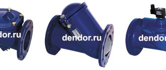
Check valve mechanisms are divided into:
- straight view;
- corner;
- spring;
- ball;
- installed using flanges;
- casement;
- installed by soldering;
- produced for beading.
Still, there is one main drawback: such an air valve is placed on the absorption tank and has a very negative effect on the combined cooling capacity.
In any case, regardless of the type and intended purpose of the mechanism, you must carefully ensure that foreign particles do not fall on the clearance part. Otherwise, even when in the closed position, the shut-off valve will not be able to fully guarantee its functionality.
In order to install any of them (meaning a type of valve), you must take into account the setup and configuration of the system. In addition, these installations are distinguished based on the specifics of their shape (square and round) and the product from which they are made. Each of the products used has its own specifics. Based on this, many mechanisms are equipped with units made using plastic, and some with metal units.
Nowadays the most popular type is the plastic valve. The throughput capacity of this mechanism is up to 6 m/s. This value is achieved due to the noiselessness when switching on and off the operating components. Such a modification of the unit can operate either with the help of a valve supplied for exhaust, or independently. It should be noted that this variety is not very popular among buyers due to being replaced by more economical analogues. Today you can purchase the most popular type of valve for compressors - the so-called “butterfly”.
These devices are made using metal, and the top is treated with a thin galvanized layer. The mechanism is equipped with two rotating blades, which are attached to the central axis. When the exhaust manifold is disconnected, the parts become short-circuited. The butterfly valve is sold in several versions, the dimensions of which range from 31 cm.
Controls and technical characteristics
The most widely used emergency valves installed on domestic heating and water supply systems have mechanical autonomous control. They operate independently when the maximum pressure is reached and are adjusted manually. Complex production plants and piping systems use safety valves that can be remotely controlled and adjusted. As a rule, when communication with the control center is lost, such a valve turns into a regular mechanical one.
Excess pressure relief valves, based on their purpose, design, and material of manufacture, have different sets of characteristics.
The main ones are:
- Trigger pressure.
- Reset pressure.
- Performance of the working environment reset channel.
- Response speed.
- Time to return to its original state (if the valve does this automatically).
A specific emergency overpressure relief valve is also characterized by the type of design, weight and size parameters, connection dimensions
Main varieties
The receiver valve in question can be classified according to a fairly large number of characteristics, the main one being the design features of the mechanism. The following execution options are available:
- Angular.
- Straight type.
- Ball.
- Spring.
- Attached by flange.
- Casement.
- Installed using soldering technology.
- Made for beading.
The classification is carried out according to the type of material used in manufacturing. Most often, the valve is made of metal with high corrosion resistance, but there are other options.
The locking element is also characterized by various design features. Based on this feature, the following execution options are distinguished:
- Ball.
- Membrane.
- With flat plate.
- Petalaceae.
- With gravity grid.
In addition, there are versions on sale in which the locking element is controlled by an electromagnetic element rather than a spring. They are more accurate in operation, but are much more expensive.
Safety valve
The relief valve (another name is safety) valve serves for emergency release of pressure and is the final device that protects the pneumatic equipment connected to the compressor from damage.
Experts also include the following types of relief valve:
- bypass valve;
- unloading valve.
Despite minor design differences, their operating principle is identical to a safety valve.
Operating principle of the safety valve
Compressor equipment that is not intended for use in industrial environments is equipped with spring-loaded safety valves. When such a compressor operates in normal mode, it is closed (see diagram). In this case, the air pressure on its plate is balanced by a calibrated spring, which prevents the locking mechanism from opening. If the pressure suddenly increases above the set value, the pressing force of the plate against the nozzle decreases and the valve begins to open. This releases excess air, after which the locking mechanism can return to its place.
Bypass valve
The bypass (or overflow) valve maintains the pressure of the working medium at a given level. To do this, through the existing branch there is a constant, and not one-time or periodic, as in a safety valve, removal of an excess amount of the working medium (compressed air, gas, liquid), which ensures pressure stability in the system. Such valves are used, for example, in turbochargers installed on automobile internal combustion engines.
Unloading valve
The unloading valve ensures the release of compressed air remaining in the manifold between the piston block and the return line when the compressor stops. In this case, the pressure at the compressor outlet is reduced to atmospheric pressure. In general, the presence of an unloading valve makes it possible to:
- relieve pressure in the line when the compressor is turned off;
- transfer the compressor to zero capacity in the absence of flow of working fluid;
- facilitate restarting of both the compressor and the connected pneumatic equipment.
In addition, the unloading valve is used in cases where it is not possible to turn off the mechanical drive of the connected pneumatic equipment. Install it at the compressor outlet in front of the return line.
So, the more productive and powerful the compressor equipment, the more complex the valve system. The simplest check valve for use in a household low-pressure compressor can be made by yourself. But for the installation to work correctly, it is recommended to purchase a factory-made part.
Types of air valves
All valves can be divided into the following types:
Safety valve: designed for situations where the compressor or pneumatic network exceeds the permissible pressure levels. In this case, it is necessary to quickly relieve excess pressure and protect the system from possible destruction.
Check valve for a compressor: necessary to contain compressed air outside the compressor, preventing it from flowing back into the installation during an emergency or planned shutdown.
An unloading valve , or as it is also called a bypass valve: this is necessary to reduce the load on the electric motor shaft at the moment the entire installation starts.
From the point of view of the properties of the air valve, the quality of operation of the entire compressor station directly depends on:
- tightness of the installed valve, i.e. depending on how tightly it fits
- on how timely the valve closes and opens
- How wear-resistant is the installed valve?
- the degree of its sensitivity to high temperatures and dynamic loads.
You can find out more detailed information on the range of valves for air compressors and their availability in stock by calling us by phone or writing a letter using the feedback form.
Favorable operating conditions for the compressor can be ensured by installing special devices, for example, a check valve. Today it is included in the delivery of most compressors, but from time to time they have to be replaced. Let's take a closer look at the features of the mechanism, as well as its purpose.
How to make a check valve for a compressor with your own hands
The modern market offers a wide variety of check valves for compressors of various types and capacities. Meanwhile, if you want to save money, you can make a valve for the compressor yourself. In order to make such a valve, it is not necessary to know the structure of an air compressor; it is enough to understand how such a compressor works. Moreover, you will not need expensive consumables and complex equipment, as well as special knowledge, skills and experience in performing work of this kind.
To make a check air valve for a receiver, compressor, vacuum chamber or any other element of a pneumatic system, you will need the following materials and tools:
- a regular fitting or a fitting with a 15 thread;
- fittings that are equipped with hoses for connecting plumbing fixtures;
- bolt with a diameter of 3 mm and a length of 40–50 mm;
- two nuts of the corresponding diameter;
- a piece of rubber cut from an old car inner tube;
- a spring whose diameter corresponds to the transverse size of the bolt;
- standard set of locksmith tools.
The fitting for the valve can be taken from an old plumbing or gas hose.
You can make a check valve for a compressor yourself using the following algorithm.
- A rectangular plate is cut out of a thin metal sheet to act as a stop for the bolt used to secure the valve. A hole is drilled in the middle part of such a plate into which the bolt should pass freely.
- At the end of the fitting, a seat is cut out on which the fixing plate will rest.
- A valve of the appropriate diameter is cut out of a piece of a car inner tube, in the middle part of which a hole is made for a bolt.
- A metal retaining plate and a spring are put on the bolt, and then a nut is screwed onto its threaded part, a rubber valve is put on, which is secured through a washer with a second nut.
- The assembled structure is inserted into the fitting and secured on both sides with nuts removed from the plumbing hose.
An air compressor is a unit whose operating principle is based on compressing and supplying air to pneumatic equipment under the required pressure. Such installations are an indispensable element both in everyday life and in industry, being an autonomously functioning technical unit or being included in more complex electrical appliances (for example, climate control or refrigeration equipment). The schematic diagram of any compressor includes a working chamber and a valve system. And since these devices, like any other mechanisms, can break down, you need to know how they are designed, what types of valves there are, how to choose them correctly or make them yourself. More on all this in the material below.
Purpose and specifics of the device
A check valve is placed on the outlet window of the mechanism head and lets in cooled atmospheric air in only one direction - to a pipe or another unit . Consequently, this valve prevents the return of compressed air located in the pipe or other elements of the pneumatic mechanism back into the installation. There is a danger of atmospheric air returning from the pneumatic mechanism to the inside of the installation during breaks in the operation of the mechanism, as well as during its start-up.
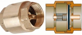
The design of a standard compressor valve consists of the following parts:
- steel body;
- entrance window that closes;
- rubber ring;
- a spiral that fits onto the valve guides;
- cork;
- sealing gaskets.
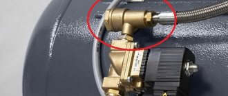
In the check valve shell, in addition to the window with which it is connected to the installation using a pipe, there is one more thing: the station unloading valve is connected to it. The purpose of such a protective mechanism on the compressor is to prevent the possible pressure in the operating chamber from exceeding.
Working conditions
- The cooled air generated by the unit enters the inlet window of the mechanism.
- Under the influence of the pressure of the cooled air, the spiral is compressed, opening the valve and letting air into the pneumatic system.
- After the installation is turned off and the air pressure in the operating chamber drops, the spiral stretches and closes the air line.
If the air pressure in the operating chamber at the moment when the installation is turned off exceeds the possible value, the safety valve, also installed at the outlet of the mechanism, is activated. The design of the station's unloading or safety valve uses a ball-type closing element, pressed to the edges of the inlet window with a special spiral. If the force directed at such a ball by compressed air exceeds that for which the spiral is configured, the valve opens, due to which the pressure is stabilized.
Safety valves in pneumatic mechanisms can also be installed on devices, for example, on pipes. In this case, the purpose of such valves is to prevent a decrease in the pressure of atmospheric air pumped into the pipe.
Mechanisms operating on the principle of a check valve, that is, cutting off the flow of a functioning substance when it runs in the opposite direction, are used in various areas.
Check valves used in mechanisms for transporting liquid substances are designed to prevent these substances from entering the installation, which may then become malfunctioning. When transporting hot gases, these stations are also used to prevent gases from reaching other parts of the mechanism.
Check valves, which are installed in ventilation systems, solve two main problems:
- guarantee a targeted refrigerant path;
- prevent the creation of reverse condensation.
Exploitation
The longevity of the protective mechanisms depends on compliance with all technical operating conditions. During operation of the protective unit, the following defects may occur due to wear of the main parts:
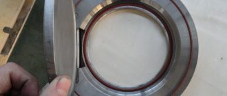
- Seat leak. The defect may occur as a result of metal shavings and scratches on the seat. The defect can be eliminated by grinding in the seat or replacing it with a similar fitting.
- Low opening pressure of the device due to the valve spring losing its elastic properties or misadjustment of the setting. To eliminate the failure, you need to replace the spring or the fitting itself, adjust the pressure, check the operation and put a seal.
- If it is necessary to replace the unit for repair, then a plug or valve cannot be temporarily installed in its place. It is necessary, for the safety of the facility, to first select a valve with exactly the same characteristics, and only install it instead of the removed one.
- If pulsation occurs during operation, rapid opening and closing of the device valve, then such a defect can cause unwanted vibration of the pipelines, which can lead to their deformation. The reason may be a mismatch between the cross-sectional sizes of the main pipeline and the pipeline connected to the unit. To eliminate the defect, it is necessary to install pipes of the same cross-section during installation.
Recommendations for use
When operating the air pressure relief valve, follow the instructions in the manufacturer's user manual.
The valve must be kept clean and must not be exposed to dust, moisture or other contaminants. It is also unacceptable to paint the valve with a brush or spray gun. This can lead to contamination of the outlet pipe and failure of the device.
Periodically, at least once a month, the valve should be tested for maximum pressure. If for any reason the valve does not operate during testing, operation of the unit should be stopped until the problems are clarified and eliminated.
Such tests should also be carried out after any removal of the valve from the unit, even if the dismantling was not associated with its repair or replacement.
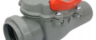
Types of check valves
There are 3 types of air returns.
- Aluminum (internal) check valve. This compressor part is considered the most durable, since it can withstand the temperature of the air passed through up to 200°C. The only drawback of this part is the rather high price, about 600 rubles.
The part is installed inside the air duct running from the cylinder to the receiver using a coupling.
Plastic return. Check valves made of plastic can be seen, for example, on the S-412 and K-24 units of the Bezhetsky class=»aligncenter» width=»600″ height=»471″|fcw3qayjh5a| src=”https://armatool.ru/wp-content/uploads/8/9/b/89be8446429f2778614b91a235395b39.jpeg” class=”aligncenter” width=”967″ height=”763″|fcw3qayjh5a| src=”https://armatool.ru/wp-content/uploads/5/5/5/5550aadb355338c8c69faafdb009ad8e.jpeg” class=”aligncenter” width=”933″ height=”960″|fcw3qayjh5a| src=”https://armatool.ru/wp-content/uploads/1/e/7/1e7725c4a1dcb2dc0e504bf589c377fa.jpeg” class=”aligncenter” width=”2048″ height=”1536″|fcw3qayjh5a| src=”https://armatool.ru/wp-content/uploads/2/a/f/2afadc121250905436d974714de613fb.jpeg” class=”aligncenter” width=”972″ height=”630″|fcw3qayjh5a| src=”https://armatool.ru/wp-content/uploads/9/6/8/9680cf45fadc8c0251628ff0f003087c.jpeg” class=”aligncenter” width=”1024″ height=”730″|fcw3qayjh5a| src=”https://armatool.ru/wp-content/uploads/f/5/a/f5a4452cd03739920062a4496e4c8b13.jpeg” class=”aligncenter” width=”409″ height=”306″|fcw3qayjh5a| src=”https://armatool.ru/wp-content/uploads/8/5/f/85f8fba3edb2413ac3d4204e11394f44.jpeg” class=”aligncenter” width=”368″ height=”250″|fcw3qayjh5a| src=”https://armatool.ru/wp-content/uploads/a/3/8/a38b8692531a21a25b9e86fcc49d8a8c.jpeg” class=”aligncenter” width=”500″ height=”400″[/img]
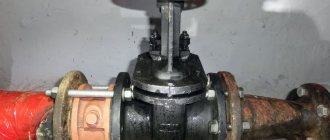
Return line made of brass. It is used on most models of compressors from different manufacturers and costs about 250 rubles. Although this unit is made mainly of metal, it fails if the air temperature during compression exceeds 140°C.
Screw compressor design
The standard model consists of the following elements.
- A filter necessary to purify the air entering the unit. Usually it consists of a primary filter, mounted directly on the housing at the point where air masses are taken from the atmosphere, and a secondary filter, which is installed in front of valve 2.
- Suction valve. Allows you to prevent the release of oil and compressed air from the compressor when it stops. Operates on pneumatic control. The design is a conventional spring-loaded valve. Some devices are equipped with proportional analogues.
- Screw block. It represents the main working part of the unit. Consists of two screws (rotors) manufactured through high-precision machining and placed in a housing. The most expensive element of the device. The rotor pair is equipped with a thermal protection sensor mounted near pipe 18. This controller turns off the motor if the temperature at the rotor outlet exceeds 105 °C.
- Belt drive (high-power models are equipped with direct clutch transmission or gearboxes). Sets the speed at which the propellers rotate. It consists of 2 pulleys, one of which is installed on the rotor pair, the other on the engine. The higher the speed, the higher the compressor performance, but the maximum pressure (working) decreases.
- Pulleys, the size of which determines the speed of rotation of the screw pair 4.
- Engine. Rotates the rotors 4 via a belt drive (in newer models - a clutch or gearbox). Equipped with a thermal protection sensor that disconnects the motor from the network when the maximum permissible values of consumed electric current are reached. Together with the sensor described in paragraph 3, it ensures the safe operation of the device and protects it from emergency situations.
- Oil filter. It cleans the oil before returning it to the rotors.
- Primary oil separator. Here the air is freed from oil under the influence of centrifugal force (the flow swirls, as a result of which the particles are separated).
- Oil separating filter. Provides a second stage of cleaning. This integrated approach makes it possible to minimize residual oil vapor at the outlet to 1.3 mg/m3, which is an unattainable value for piston units.
- Safety valve. Necessary for safety. The valve is activated if the pressure in the oil separator 8 exceeds the permissible limit.
- Thermostat providing the desired temperature. It passes the oil composition, not heated to 72 °C, past the cooling radiator 9. This allows you to speed up the achievement of the optimal temperature.
- Oil cooler. After being separated from the compressed air, the hot oil enters this tank, where it is cooled to the desired temperature.
- Air cooler. Before being supplied to the consumer, the compressed air is cooled here to a temperature that is 15–20 °C higher than the environment.
- Fan. Intakes air and cools working elements.
- Idle valve (electro-pneumatic). Controls the functioning of suction valve 2.
- Pressure switch. Ensures the unit operates in automatic mode. In new compressors, the relay is replaced by an electronic control system.
- Pressure gauge. Located on the front panel, it shows the pressure inside the compressor.
- Outlet pipe.
- A transparent cylindrical thickening on the tube, necessary for visual control of the oil return process.
- Minimum pressure valve. As long as the latter does not exceed 4 bar, it will always be closed. This element also functions as a check valve, since it separates the pneumatic line and the compressor when the latter stops or operates in idle mode.
The device is housed in a housing, which is usually made of steel. It is coated with a non-flammable sound-absorbing compound that is resistant to oil and other similar substances. This is the design of the most common modification. Depending on the model and manufacturer, the design and configuration of the rotary compressor may vary.
Compressor operating principle
Through valve 2, air from the atmosphere, purified by filters 1, enters the rotor pair 3. Here it is mixed with oil. The latter is fed into the compression tank to perform the following tasks.
- Seal the gaps between screws 3 and housing 16, as well as between the cavities of the rotors. This allows you to minimize overflows and leaks.
- Eliminate contact between the screws by ensuring an oil wedge between them.
- Dissipate heat that is induced during air compression.
The air-oil mixture compressed in block 3 is supplied to the oil separator 7, where it is divided into components. The separated oil is cleaned on filter 6 and returned to block 3. Depending on the temperature, it can be pre-cooled in radiator 9, which is regulated by thermostat 8. In any case, the oil will circulate in a closed circle. The air enters the cooling radiator 13. After reaching the desired temperature, it is supplied to the compressor outlet.
Operating modes
- Start _ _ This mode serves to optimize the load on the electrical network when the compressor starts. The engine is turned on according to the “star” circuit, and after 2 seconds (counted by a timer, which turns on when you press the Start button), it switches to the “triangle” circuit, which corresponds to the operating mode. Low-power screw models operate on direct start.
- Worker. The pressure in the system begins to increase. To control it there are 2 pressure gauges. The first one is on the front panel and shows the parameters inside the compressor. The second is on the receiver, it serves to control the line. After reaching the maximum permissible pressure, the corresponding relay is activated, as a result of which the unit switches to idling from the operating mode.
- Idling. The engine and rotors rotate, moving gas along an internal circuit. This is necessary to cool the air masses. This mode serves to put the compressor into a standby state or acts as a preparation before shutting down completely. There is no idle speed in piston models. A detailed description of the device’s operation in this mode is as follows. Relay 16 gives the command that activates the idle air valve and the timing relay. The latter's parameters can be configured. The pneumatic valve opens the channel between the oil separator filter 9 and the suction valve 2, as a result of which the pressure inside the compressor begins to decrease at such a rate as to reach the minimum mark (2.5 bar) within a set time. This allows you to stop the engine without releasing oil into filter area 1. After the specified period, the time relay gives the command to turn off the engine. The system enters the standby state. If the compression reaches a minimum value before the time relay is triggered, the operating rhythm starts again.
- Expectation. Continues until the operating pressure drops below the minimum mark, after which relay 16 starts the mechanism again. The duration of this mode depends on the rate of air consumption.
- Stop . _ Serves for normal shutdown of the unit. If the compressor was in operating rhythm, it will go to idle for a while and only then turn off.
- Alarm – stop – emergency shutdown. The corresponding button is located on the control panel. The mode is used in cases where it is necessary to urgently stop the engine. The unit turns off immediately, without an intermediate transition to idle speed.
Application of safety devices
To ensure safe operation, a safety fitting is a must for any pressure system.
Depending on their purpose, they can be installed in the following places:
- Hot water supply and heating. The safety valve for the heating system is installed on the pipelines after the supply pump. Since hot water is corrosive, the discharge must be directed to a safe location, usually a drain. At high costs, the number of units can reach 2 or more.
- The plumbing fitting for cold water supply is installed in drinking water supply pipelines. The discharge is made directly to the ground.
- Hydraulic system. Hydraulic oils are used as the working fluid. The hydraulic system serves to drive working mechanisms: hydraulic motors, hydraulic cylinders. The safety fitting is installed on pipes, or can be part of a pump or hydraulic distributor. The oil is discharged into the drain line.
- Gas supply pipelines. An increase in pressure in the pipes can lead to an emergency situation - flame separation from the burners, accumulation of excess gas and an explosion in the room. Therefore, the fittings are installed immediately after the pressure regulator, and the discharge is carried out into the atmosphere.
- Air system, compressors. A protective device is installed in the compressor housing and is discharged into the atmosphere.
Compressor safety fitting
Application area
Compressors have become very widespread. The device in question is used in the following cases:
- Laying a pipeline through which various gases are transported.
- When creating refrigeration units.
- In the line, which is designed to absorb various liquids.
- Protection of ventilation ducts or air conditioning.
- Closing the pipeline that drains wastewater.
Check valves are also installed in systems that prevent liquid from entering the compressor. Such a situation can lead to the device becoming unusable.
The device in question is actively used in ventilation systems. They are required to solve the following tasks:
- Preventing the possibility of penetration of cold currents from outside the structure.
- Increased draft in the ventilation system in case of strong branching.
- Eliminates the possibility of foreign odors.
- To protect the environment from various harmful substances.
- Shutting off shafts and other currents to eliminate the possibility of combustion products spreading.
In general, we can say that the check valve is an important part of a wide variety of designs. Its reliable operation ensures a long service life of the compressor.
Source
Purpose of the air collector or why do you need a receiver in the compressor?
Among all types of installations designed to compress various media, piston and screw units are most widespread. The former compress air due to the reciprocating movement of the piston. In this case, a vacuum or an increase in pressure alternately occurs in the cylinder. As a result, in the case of direct connection, pulsation occurs in the pneumatic system of the enterprise. When operating screw units, this effect is not so pronounced, but is also present.
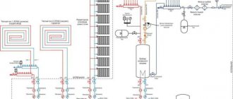
At the same time, we note that a significant part of pneumatic equipment is sensitive to the quality of the compressed air supply, therefore, with constant pulsation in the system, it quickly fails. The solution to the problem was the use of air collectors, which dampen the surge and ensure a stable supply of compressed air to the tool. However, pressure equalization is an important, but not the only answer to the question of why a receiver is needed in a compressor. In addition, tanks solve other problems, including:
Air accumulation. Using an air collector, you can eliminate the problem of peak loads that arise in an enterprise when a large number of consumers are simultaneously connected. Without using a receiver, this problem can only be solved by replacing the compressor with a more powerful model, which is most often impractical due to the high cost of the units. Additional cooling and condensate removal. In accordance with the laws of physics, during compression the temperature of the working medium increases. After the air enters the plant's pneumatic system, it cools down again. In this case, the moisture contained in it falls out in the form of condensation. This leads to metal corrosion and equipment damage. The receiver solves this problem too. It is built in between the compressor and consumers. A decrease in the temperature of the working environment and condensation occurs precisely in the air collector, as a result, the equipment is reliably protected from moisture. The latter, by the way, is removed from the receiver through a special drain valve. Reduced vibration. Both gasoline and diesel internal combustion engines, as well as electric motors, vibrate during operation.
It is important to note that an increase in vibration leads to an increase in the level of noise pollution in the room, as well as to the destruction of the base on which the unit is installed. The use of an air accumulator with a volume of 500 liters or more can significantly reduce engine vibration.
We have listed the main answers to the question of why a receiver is needed in a compressor. As for other significant functions of the air tank, these include:
- additional cleaning of the working environment from dust and other contaminants;
- increasing the energy efficiency of equipment;
- reduction of compressor on/off cycles;
- reduction of compressed air cooling costs;
- neutralization of turbulence that is formed during gas injection.
As you can see, air receivers solve many problems related to ensuring stable operation of consumers. Practice shows that in many cases normal operation of an enterprise is impossible without the use of air accumulators. And where it is possible to do without them, installing a receiver reduces operating costs, extends the service life of equipment, and increases the efficiency of equipment.
Note! In telling why a receiver is needed in a compressor, we did not pursue advertising purposes. The main objective of this article is to provide you with the most detailed information about air accumulators
Should I buy a receiver for the compressor or not? Each user makes this decision independently. For our part, we are ready to advise you on all issues. If after reading the material there are still any uncertainties, contact our specialists for additional information or assistance in choosing a receiver.
Prepared by: Dmitry Zaporozhtsev
Device Features
Check valves are used in many applications. Such devices most often work in tandem with some kind of tanks or compressors. The main task of a check valve is to prevent loss of pressure built into the system and limit the access of unwanted elements into the system.
In the absence of such a mechanism, the efficiency of the equipment decreases noticeably. For example, compressors are forced to work almost non-stop, which affects not only the operational life of the equipment, but also electricity bills.
Areas of application for check valves:
- systems operating with the distillation of liquid media;
- gas lines;
- refrigeration equipment;
- ventilation;
- plumbing equipment.
In addition to maintaining system pressure, check valves prevent liquid media from entering the compressor. With large volumes of distillation, as well as a serious load on the equipment, it is very important to maintain the tightness of the equipment. This point is also critical when working with gaseous compositions, especially hot ones.
Exploitation
The longevity of the protective mechanisms depends on compliance with all technical operating conditions. During operation of the protective unit, the following defects may occur due to wear of the main parts:
- Seat leak. The defect may occur as a result of metal shavings and scratches on the seat. The defect can be eliminated by grinding in the seat or replacing it with a similar fitting.
- Low opening pressure of the device due to the valve spring losing its elastic properties or misadjustment of the setting. To eliminate the failure, you need to replace the spring or the fitting itself, adjust the pressure, check the operation and put a seal.
- If it is necessary to replace the unit for repair, then a plug or valve cannot be temporarily installed in its place. It is necessary, for the safety of the facility, to first select a valve with exactly the same characteristics, and only install it instead of the removed one.
- If pulsation occurs during operation, rapid opening and closing of the device valve, then such a defect can cause unwanted vibration of the pipelines, which can lead to their deformation. The reason may be a mismatch between the cross-sectional sizes of the main pipeline and the pipeline connected to the unit. To eliminate the defect, it is necessary to install pipes of the same cross-section during installation.
Design and principle of operation of the pressure regulator
A gas pressure regulator or pressure reducing valve is designed to reduce the pressure in the line diverted from the main line and maintain this pressure at a constant level.
Pressure regulators are used to maintain the pressure required for the operation of pneumatic, gas or other equipment.
For example, pressure reducing valves are installed on gas cylinders and allow you to adjust the required pressure in the line discharged to the consumer. Reducing valves installed on cylinders are often called pressure reducers, since they reduce or reduce the pressure in the outlet line (reduction - reduction, reduction, reduction).