The main task that a flanged check valve, installed on pipelines for various purposes, solves is to ensure the movement of the transported medium in one direction. The design features of the check valve, for the installation of which a flange is used, allow such a device to automatically stop the movement of the transported medium at the moment when such movement begins to occur in the wrong direction. Flange-type check valves are installed primarily on pipelines through which liquid media are pumped.
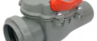
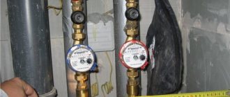
Cast iron wafer check valve in the water meter assembly
Features and applications of check valves
Check valves of various types (including flanged) are used to protect pipelines from:
- the occurrence of reverse flows of the working environment in it;
- hydraulic shocks.
Reverse flow in pipelines, as is clear from its name, is the movement of the working medium in the opposite direction. This can happen, in particular, when the pump that supplies the working fluid and moves it is turned off. If for heating systems such a phenomenon as reverse flow is not particularly critical, then in sewer and water supply systems, as well as in pipelines through which petroleum products and other media are transported, its occurrence cannot be allowed. That is why the use of check valves in such pipeline systems is a mandatory requirement.
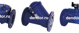
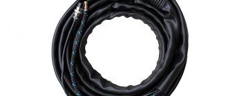
Stainless steel flanged check valve designed for use in petroleum products environments
Another undesirable phenomenon from which pipeline systems can be protected by a flanged, wafer check or any other valve is water hammer. It is characterized by the fact that a sharp pressure drop in the transported medium occurs in the pipeline, which leads to the formation of a shock wave passing along the entire length of the pipeline system.
Water hammer can, over time, lead to the destruction of individual sections of the pipeline and the failure of elements that are used to ensure its normal operation. With the help of check valves installed using flanges or any other method, the system is divided into separate isolated sectors, which makes it possible to effectively protect it from the effects of water hammer.
Working Environments
Check valves perform well in aggressive and non-aggressive gas and liquid environments. Let us remember that aggressive ones are oil, chemical compounds, gases, including radioactive ones. Non-aggressive media - liquids with biological elements, steam, water of any temperature, waste water, fats.
Check valve RF 8686
Look
Reverse valve model 400-407
Look
Reverse valve 409
View Sealing is ensured by metal and rubber seals.
Operating principle
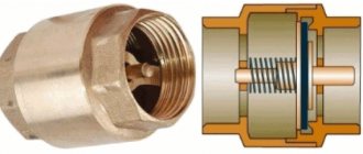
The principle by which check valves operate is quite simple, however, such devices are very effective and are able to provide reliable protection of parts of pipeline systems. Any check valve, regardless of type, consists of a body (steel or cast iron) and a locking element located in it. The locking mechanism operates due to the pressure of a special spring, the rigidity of which can be adjusted.
The spring with which check valves are equipped ensures that their locking elements open in only one direction - in the direction of the correct movement of the transported medium. By exerting pressure on the shut-off element held by such a spring, the liquid or gas pumped through the pipeline opens it and begins to move in the required direction. As soon as the pressure of the working medium in the direction of opening the valve begins to fall, the shut-off element closes, preventing the liquid or gas from moving in the opposite direction.
Operating principle of a check valve
Manufacturing technology and groups of materials used
For the manufacture of components and parts that make up the valve, various materials are used, which are divided into 4 groups:
- Materials for making the case. They must have good casting properties, a sufficient level of strength and corrosion resistance, and be subject to mechanical processing. Basically, the valve body is manufactured using casting technology.
- Materials for sealing the places where the spindle passes through the cover. Gaskets must be elastic, heat-resistant, moisture-resistant, durable and inexpensive products.
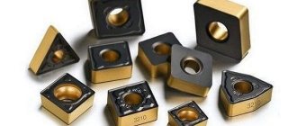
- Seals in the area of the seat and valve. The material for their manufacture must also have elasticity, wear resistance and anti-friction properties.
- Lubricants that reduce the coefficient of friction in the moving parts of the valve.
The body materials most often used in the manufacture of valves are:
- brass. This is a yellow plastic metal that can be easily machined (grinding, polishing, etc.). It is an alloy of pure copper with a small amount of impurities. Among the alloying elements of alloys, zinc and tin can be distinguished, which increase the anti-corrosion properties and thermal conductivity of the material. Brass valves are one of the most reliable models in operation, but expensive;
- cast iron. A heavy gray metal with high strength and corrosion resistance. Cast iron valves are inexpensive, can withstand ambient temperatures up to 200º, but are not very resistant to dynamic loads, so they can easily crack from a strong blow to the body.
- steel. The material is quite plastic and easy to process. The steel reinforcement body is resistant to mechanical stress and strong impacts. Products for the manufacture of which high-alloy steel (stainless steel) is used, in addition to high strength, have absolute resistance to any type of corrosion processes, resistance to high temperatures, and durability.
Types and properties
The design of the shut-off elements of check valves, for installation of which flanges are used, can be different. The choice of a flange valve with a certain type of locking element depends on the tasks for which such a device is intended.
So, depending on the design of the locking element, there are:
- rotary valve;
- lift type check valve;
- check valve with ball shut-off element;
- double-leaf check valve;
- intake check valve equipped with a mesh.
Design of some flange type check valves
A rotary check valve is a locking device, the main part of which is a steel slamming disk fixed on a spring-loaded axis. At the moment when such a check valve is open, the disk in its inner part is located parallel to the movement of the working medium, and when closed, it is perpendicular. The flange check valve has a simple design and, accordingly, low cost. If we talk about the disadvantages of check valves of this type, the most significant of them is that their rotating mechanism at the moment of closing slams the locking disk too tightly, which over time leads to wear of the seat. Rotary check valves, equipped with a special mechanism that ensures smooth closing of the locking disc, do not have this drawback. Meanwhile, such improved flanged rotary valves are more expensive, which somewhat limits their use.
Rotary check valve device
In flange-type lifting check valves, a special spool is used as a shut-off element, which, under the pressure of the working flow, rises along the vertical axis, and when the pressure decreases, it drops to its seat, blocking the movement of the medium transported through the pipeline. It should be borne in mind that such valves, due to their design features, can only be installed in a vertical position.
Ball check valves, as their name suggests, use a ball-shaped spool as a shut-off element. Their large size does not allow them to be used as wafer locking devices.
Flanged ball type check valve
A double-leaf check valve, which is produced mainly in a wafer design, involves the use of two slamming flaps simultaneously in its design. Each of them is connected to a spring, which regulates the strength of their resistance to the pressure of the working flow. The wafer-type double-leaf valve, due to the small size of its shut-off elements - the flaps - is characterized by very compact dimensions.
Check valves, which are additionally equipped with a strainer, are used for installation on pipeline systems for pumping oil, gas or water from underground sources. Such devices, the most popular model of which is 16CH42R, simultaneously solve two important problems: their locking mechanism prevents liquid or gas from returning back to the source, and the mesh protects the pipeline from large debris entering it.
The design of the 16CH42R valve varies depending on the dimensions of the product
Model 16Ch42R, the body of which is made of steel or cast iron, is characterized by wide versatility and can be installed on pipelines or pumps used for pumping both liquid and gaseous media.
Overall and connection dimensions of the valve 16х42р
Classification by connection method to workflow
Types of connecting fittings to the process have been developed in several options:
- flanged - flanged fittings are made with hardware parts on the connecting pipes (flanges). They can be square, hexagonal or round in shape with evenly spaced holes for mounting bolts. The pipeline must also have a counter flange with similar connecting dimensions;
- coupling - devices are connected to the process using couplings with internal threads;
- pin-type - the fittings are fastened using an external thread with a collar under the control; a sealing gasket is used to seal the connection;
- fitting - this type of connection is a threaded pair, when fittings with external threads are attracted to the pipeline with a union nut;
- welded - devices are attached to the pipe by welding.
Flanged and Wafer Check Valves: Differences
Check valves that use flanges for installation on piping systems can be one of the following types:
- flanged;
- wafer
On flange-type devices, the supply flange and the return flange are welded to the valve body and form a single unit with it. Flanged check valves are used primarily to equip large-diameter pipes, with the help of which working media are transported on an industrial scale.
On the left is a wafer valve, on the right is a valve with flange mounting
Wafer check valves have virtually no fastening elements. This type of installation, as mentioned above, is very often used for installing double-leaf check valves. In this case, the valve itself (in particular, a double-leaf wafer valve) is installed between two flanges fixed at the ends of the connected pipes. After its placement in special seats, which are equipped with sealing elements, the flanges are tightened together using threaded rods. Despite the apparent unreliability of such a connection, if it is made correctly, the wafer check valve is fixed with the same reliability as devices of any other type.
Check valves can be installed on pipeline systems using not only flanges, but also couplings or a welded connection. However, if we talk about large-diameter pipelines, such valves are installed on them only using flanges.
The installation method of the check valve depends on its design
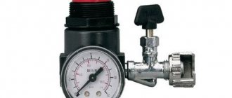
Pressure
Another important design feature of all products that make up a flange connection is the nominal pressure that the connection can withstand. Pressure indicators depend on the geometric dimensions of the flange and the design of the sealing surface. A steel flat welded flange (GOST 12820-80, Fig. 1) and a steel free flange on a welded ring (GOST 12822-80) can withstand pressure up to 25 kgf/cm2, but a steel butt welded flange (GOST 12821-80) can withstand pressure up to 200 kgf/cm2.
At the same time, the peculiarity of this indicator is that it can be expressed in various units of measurement: kgf/cm2, Pa, MPa, atm., bar. The unit of measurement in the production and designation of flanges is kgf/cm2.
The main grades of steel for the production of flanges are the following:
• Steel 20 or abbreviated St. 20 (regulated by GOST 8479-70) - high-quality carbon structural steel. Flanges made of such steel st. 20 are most common and are used when installing various pipeline fittings in pipelines (water, steam, etc.) with an external temperature not lower than -40 degrees and an internal temperature not higher than +475 degrees Celsius.
• No less common in the manufacture of flanges is the steel grade 09g2s, abbreviated as art. 09G2S (corresponding to GOST 19281-89) – this is a low-alloy structural steel for welded structures. Its difference from steel 20 is that 09g2s flanges can be operated with external temperatures up to -70 degrees. And accordingly (oil, natural gas, etc.), however, the temperature of the working environment should not exceed + 475 degrees Celsius.
• Steel grade 12Х18Н10Т (corresponds to GOST 25054-81) – this steel is structural cryogenic. Flanges made of steel 12Х18Н10Т can be used in aggressive conditions, for example, dilute solutions of nitric, acetic, phosphoric acids, solutions of alkalis and salts, with an operating temperature range from -196 to +350 degrees Celsius.
• Steel grade 10Х17Н13М2Т (corresponds to GOST 25054-81) – this grade is corrosion-resistant ordinary. The use of such products in highly aggressive environments is permitted; they are resistant to electrochemical and chemical corrosion, stress corrosion, etc., and the permitted temperature range is from -196 to +600 degrees Celsius. Has a long service life.
• Steel grade 15Х5М (GOST 20072-74) has heat resistance properties and is low-alloy. This steel is used for the manufacture of flanges capable of high resistance to oxidation at temperatures of 600-650 degrees. Possesses heat resistance.
Of course, in addition to the listed steel grades, other steel grades can be used in the production of steel flanges, for example: 13KhFA, 10G2FBU, 08Kh18N10T, 17G1S, 10G2S, 30KhMA, 40Kh and others.
Advantages and disadvantages of flange type check valves
Since flange-type check valves are most often used to equip pipelines through which the working fluid is transported with high intensity, the internal elements of such devices (in particular, the shut-off mechanism) experience significant shock loads during operation. In addition, a flange-type check valve, due to its significant dimensions, itself causes water hammer. During the process of closing the valve flaps, the pressure in the pipeline in which it is installed inevitably increases, which leads to the formation of a water hammer.
In those pipeline systems in which water hammer is not able to have a significant impact on the performance of both individual elements and the system as a whole, simple type check valves are used. The diameter of the latter, as a rule, does not exceed 400 mm. In other cases, non-impact type check valves are used. Smooth and soft closing of the shut-off element in shockless flanged valves can be ensured by special weights or hydraulic dampers. Meanwhile, when choosing non-impact type check valves to equip a pipeline system, you should keep in mind that they can only be installed in horizontal sections.
Axial type flanged hammerless valve
The most significant advantages of flanged check valves include:
- compact dimensions, which allows the installation of such devices in almost any area of the pipeline system;
- the ability to operate effectively even in systems where the working environment is highly polluted;
- Possibility of installation on pipelines with large diameters.
Conclusion
Flanged fittings are an important component of piping systems and are supplied by both valve and pipe manufacturers in many configurations. Complete knowledge of the design and applicable standards is essential to the successful implementation of a piping system.
In the plumbing industry, valve and pipe flanges are available in many alternative materials and conflicting pressure ratings. To avoid serious design problems and unnecessary costs, careful knowledge of flange fitting performance and the specification of flanged systems that meet the required pressure and temperature requirements of the piping system are required.
Features of choice
The main parameters that you should pay attention to when choosing a check valve (including flanged ones) are:
- operating pressure at which such a device can operate;
- nominal diameter.
You can find out what operating pressure the check valve corresponds to by looking at the device’s marking, in which this parameter is designated by the letters RU. The numbers in the marking after such letters indicate the operating pressure for which the device is intended. For example, the designation RU16 indicates that a flanged valve can operate at a pressure of 16 bar without being subject to excessive wear.
Check valve marking
The nominal diameter, which determines which pipeline a flange-type valve can be installed on, is indicated by the letters DU. Accordingly, the numbers following these letters in the marking indicate the value of the nominal diameter of the check valve in millimeters. When choosing a check valve according to this parameter, keep in mind that such a product can only be mounted on pipeline elements that have the same dimensions. In other words, the DU80 model, for example, can only be installed on pipes or other elements of the pipeline system, the mounting diameter of which corresponds to 80 mm.
Flange geometry
Flanged fittings are structural members of a piping system that support the pipe loads associated with that system because the member is a rigid or restrained hinge. The flange connection will not slide or rotate, and it must withstand internal pressure forces without any external restriction. Some pressure and mechanical connections of devices that are often used underground are not restrained. This is an important distinction that affects the supports, anchors, and thrust units required for many systems.
The basic fitting on most valves and water pipe fittings consists of a circular ring or flange welded to or cast from a cast body and pipe. The main flange dimensions consist of:
- outer diameter (OD)
- bolt circle diameter (BC)
- thickness (T)
- number and size of bolt holes
The bolt pattern in valves and fittings typically falls along a vertical centerline. The flanges of the two fittings are connected together and sealed with an elastic gasket, which is tightly compressed by bolts located in a circle concentric with the outer diameter of the pipe. To achieve a tight seal, the bolts must withstand the hydrostatic end force of the pipe and compress the gasket to a multiple of the maximum system pressure.
Flanged valve assembly with eight threaded flange ports. Due to the body shape of some valves, valve flanges often contain threaded holes instead of through holes, which affects bolt selection. For a nominal pipe size eccentric plug valve, four threaded holes are required on the top and four threaded holes on the bottom of the flange because the nuts behind the flange will interfere with the main part of the valve body.
Installation recommendations
When installing flanged check valves, the following rules must be strictly adhered to.
- Installation must be carried out by specialists who have previously been trained and have received permission to perform work of this kind.
- The part of the pipeline system where installation is carried out is completely disconnected from the supply of the working medium.
- Before starting installation, you should make sure that the installed product’s characteristics fully comply with the climatic conditions in which it will be used.
- If a wafer check valve is installed, its flanged part is first mounted, and only then is it fixed in it.
- Before introducing a flow of working fluid into the pipeline, you should once again make sure that the check valve is installed securely and all required connections are made.
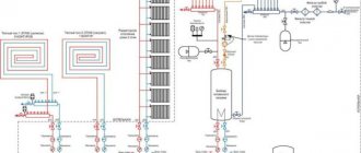
Installation diagram for flanged check valve
And in conclusion, a short video with a visual demonstration of the principle of operation of a rotary check valve.
Pipe fittings from an official dealer
Trading house "NHI-Group" is the official representative. The store presents original pipeline fittings that fully meet the requirements of GOST, designed for many years of service with precise performance of their functions. To purchase, simply add the required devices to your cart and place your order. If necessary, our specialists will help you with the selection of equipment to complete your pipeline.
We offer customers the best prices for pipeline fittings from an official dealer. We deliver fittings throughout Russia and the CIS countries using reliable transport companies.