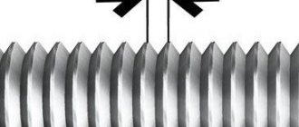
Determination of readings by vernier
To determine the readings of a caliper, it is necessary to add the values of its main and auxiliary scales.
- The number of whole millimeters is counted on the bar scale from left to right. The pointer is the zero stroke of the vernier.
- To count fractions of a millimeter, it is necessary to find the vernier stroke that most accurately matches one of the strokes of the main scale. After this, you need to multiply the serial number of the found vernier stroke (not counting zero) by the value of its scale division.
The measurement result is equal to the sum of two quantities: the number of whole millimeters and fractions of mm. If the zero line of the vernier exactly coincides with one of the lines of the main scale, the resulting size is expressed as an integer.
The figure above shows the readings of the ShTs-1 caliper. In the first case they are: 3 + 0.3 = 3.3 mm, and in the second - 36 + 0.8 = 36.8 mm.
Vernier with 0.05 mm division
The instrument scale with a division value of 0.05 mm is presented below. For example, two different indications are given. The first is 6 mm + 0.45 mm = 6.45 mm, the second is 1 mm + 0.65 mm = 1.65 mm.
Similar to the first example, you need to find the strokes of the vernier and the rod that exactly match each other. In the figure they are highlighted in green and black, respectively.
Vernier calipers - classification and marking
The measuring instrument, a caliper, can be of 3 types and about 8 standard sizes, at least according to domestic regulatory documents
Moreover, when purchasing any precision instrument, it is important to focus on the standards by which it is manufactured and calibrated. It is divided into types depending on the indicator of the measured value from which we take the required numbers
These can be vernier (ShTs), dial (ShTsK) and digital (ShTsTs) calipers. In the first case, we will have to run our eyes over both scales, count the divisions and report the result. In the second case, we will see numbers on a mechanical scale with a moving arrow, but in the third case, we will be shown the finished result on the display.
Within these types, further subspecies can be divided depending on the design and length of the main line. For example, you can divide tools by the type of material from which they are made. An example of a hard alloy tool is ShTsT-I. There are differences in the design of the jaws or additional accessories. Thus, ShTs-I and ShTs-III differ in the location of the jaws; in the first case it is bilateral, and in the second it is unilateral. But the ShTs-II has a micrometric feed frame, which will make marking easier if you need to transfer your measurements to another plane. There is no point in discussing the differences in standard sizes for a long time; one has only to say that the larger the ruler, the greater the error in the obtained values.
Photo of the ShTs-2 caliper, antok.by
Photo of caliper, antok.by
Photo of digital caliper, tehnoalat.rs
Photo of dial caliper, tehnoalat.rs
Photo of digital composite caliper, tehnoalat.rs
Mechanical caliper device
The design of a double-sided caliper with a depth gauge is shown in the figure. The measurement range of this instrument is 0-150 mm. With its help, you can measure both external and internal dimensions, the depth of holes with an accuracy of 0.05 mm.
Essential elements
- Barbell.
- Frame.
- Sponges for external measurements.
- Sponges for internal measurements.
- Depth gauge ruler.
- Locking screw for fixing the frame.
- Vernier scale. Serves to count fractions of millimeters.
- Bar scale.
The jaws for internal measurements 4 are knife-shaped. Thanks to this, the hole size is determined on a scale without additional calculations. If the caliper jaws are stepped, as in the ShTs-2 device, then when measuring grooves and holes, their total thickness must be added to the readings obtained.
The reading value of the vernier may differ for different instrument models. So, for example, for ShTs-1 it is 0.1 mm, for ShTs-II it is 0.05 or 0.1 mm, and the accuracy of devices with a vernier reading value of 0.02 mm approaches the accuracy of micrometers. Design differences in the design of calipers can be expressed in the shape of a moving frame, measurement ranges, for example: 0–125 mm, 0–500 mm, 500–1600 mm, 800–2000 mm, etc. The accuracy of measurements depends on various factors: the reading value on the vernier, work skills, and the good condition of the instrument.
How to measure pipe diameter
When laying pipelines, installers are faced with various options for their location, which often determines how the pipe is measured. To find the necessary parameters at home, they usually use any measuring instrument that is at hand, and, if necessary, a simple calculation formula.
In production, measurements are mainly carried out for control by more complex, high-precision instruments (for example, a laser meter or a ruler, a circummeter, is used).
Rice. 12 Methods of installing fittings on PEX pipes: compression, tension couplings, press fittings, push fittings
How to measure the diameter of a pipe with a ruler and tape measure
A tape measure or ruler can almost always be found in households; they can be used to find out the parameters of a pipe cut across. To determine the dimensions, apply the tools to the pipe end and look at their scale, visually comparing its readings with the cross-section of the product. The accuracy of this method is low - it is difficult to take measurements accurately diagonally.
If communications are located in hard-to-reach places and are not cut, it becomes too difficult to accurately determine the diameter of the pipe with a tape measure or using a ruler. You will have to attach rectangular parts to the wall around the pipe shell on both sides and measure the distance between them as close to the shell as possible to reduce the error.
Rice. 13 How to measure the diameter of a pipe with a tape measure and ruler
Using a caliper
A caliper is a fairly convenient measuring tool for determining internal and external dimensions in a circle up to 150 mm with an accuracy of 0.1 mm. Modern devices, in addition to a mechanical scale, may have an electronic or dial indication.
It is convenient to use a caliper to measure the pipeline in hard-to-reach places, touching or even partially located in the wall, less than half of the screed. An accuracy of 0.1 mm is quite acceptable for any business purpose.
Even more accurate readings can be obtained by using a micrometer, however, if calipers are occasionally found in the household, then a micrometer is an expensive industrial control and measuring device, the high accuracy of whose readings is not needed in everyday life.
Rice. 14 How to measure the diameter of a pipe with a caliper
How to measure the diameter of a pipe using string and the formula
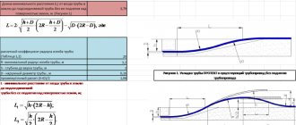
Sometimes solving the problem of how to measure the diameter of a pipe is difficult due to the inconvenience of taking measurements and the large overall dimensions of the pipeline - in these cases, a combined method can be used.
To do this, tie the pipe with thread or rope (several turns can be made), and mark them with a marker or pen. Then lay the thread on the table and measure the distance between the marks. The resulting value is divided by pi, equal to 3.142, and the desired size is obtained. This method of calculating the diameter allows you to find out the parameters of the pipeline with higher accuracy thanks to the thousandth values of the number pi and the greater extent of the circumference than the directly measured parameter.
Sometimes it is difficult to determine the internal pipe size for a number of reasons; in this case, the problem of how to determine the pipe diameter is solved using a complex method. First, measure its external size in a circle, then the thickness of the wall, after which, using the formula, divide the first indicator by the number pi and subtract double the thickness of the shell from it.
Rice. 15 How to measure the diameter of a pipe using measuring tapes and the appearance of the circometer
Measuring tapes
One of the fastest ways to measure the diameter of a pipe is to use tapes with dimensional scales. Sometimes, for these purposes, a construction tape is used, which has a flexible tape with marked divisions and length values.
In everyday life, a measuring tape is often used, which is used to determine the size of clothes in sewing; it can also be used similarly to a tape measure. After measuring the length along the outer circle, a simple calculation is carried out: the result is divided by 3.142 and the outer diameter is found in this way.
An analogue of household tape meters is an industrial circummeter - a special device with a graduated flexible steel strip for measuring circumference lengths.
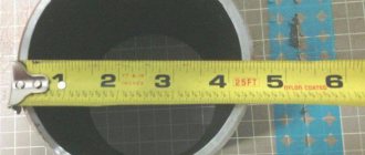
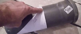
Photo copy method
The photographic method allows you to find out the parameters of the pipeline in extreme and emergency conditions in the absence of lighting, poor access to communications, and a limited time interval. When measuring pipe diameters using photography, place a tape measure with divisions or any object that can be taken with you next to the pipe, and take a photograph with a camera or cell phone. Then, under calm conditions, the photograph is analyzed, comparing the dimensions of the digital tape measure or the dimensions of the object with the parameters of the pipe.
Rice. 16 Comparative table of diameters of water pipes made of various materials
Thanks to the standard range of standard sizes of steel, copper, and polymer pipelines, the problem of how to find out the diameter of a pipe is, in most cases, successfully solved by studying the relevant state standards. If for some reason there is a need for measurements, for household purposes it is quite possible to get by with a ruler, tape measure, use measuring tapes or a piece of string, obtaining the desired result using a simple formula.
The procedure for carrying out measurements, checking serviceability
Before work, check the technical condition of the caliper and, if necessary, adjust it. If the device has warped jaws, it cannot be used. Nicks, corrosion and scratches on working surfaces are also not allowed. It is necessary that the ends of the rod and the depth gauge ruler coincide when the jaws are aligned. The instrument scale must be clean and easily readable.
- The caliper jaws are pressed tightly against the part with little force, without gaps or distortions.
- When determining the outer diameter of a cylinder (shaft, bolt, etc.), make sure that the plane of the frame is perpendicular to its axis.
- When measuring cylindrical holes, the jaws of the caliper are placed at diametrically opposite points, which can be found by focusing on the maximum scale readings. In this case, the plane of the frame must pass through the axis of the hole, i.e. Measurement along the chord or at an angle to the axis is not allowed.
- To measure the depth of a hole, a rod is placed at its edge perpendicular to the surface of the part. The depth gauge ruler is pushed all the way to the bottom using a movable frame.
- The resulting size is fixed with a locking screw and the readings are determined.
Length measurement
Correct length measurement is ensured by the parallel position of the rod in two planes to the line of the measured length.
Parallelism to the rod surface
Parallelism to the rod surface
Failure to parallelize the side surface of the bar or rib to the size line will cause a false size to be taken.
False size
The increased length of contact of the jaws with the surfaces, as well as the application of the rod to the surface of the axis of the part, will help to establish the correct position of the tool.
Reliable tool contact
Measuring internal lengths
The plane and edge of the rod must be parallel to the dimension line. The photo shows the incorrect and correct position of the tool when taking a size.
Incorrect position
Correct position
Correct position of the SHTs-2 tool
Correct tool pressure
Now that the correct positioning of the instrument has been determined, all that remains is to ensure tight contact of the measuring surfaces with the counter surfaces.
It is very important to ensure that the contact does not fall on the radius at the corners of the ledges. Correctly made pressure to the surface should be tight, eliminating the presence of any gaps
Correctly made pressure to the surface should be tight, eliminating the presence of any gaps.
The gap formed by a loose clamp, together with the actual size, will be shown by the caliper reading device, but this data will be false.
Typically, the jaws are pressed against the surfaces of the part by force applied directly to the frame or through a feed roller.
This clamping method can ensure sufficient stability and accuracy in measurements. With an increase in measured lengths, when the clamping force must be more rigid in order to form reliable clamping to the measured surfaces.
Using this method carries the risk of obtaining false results.
The fact is that increased pressure on the main frame can cause the frame to warp along with the moving jaws.
Frame skew
Increasing the pressure on the frame with the locking screw will help eliminate the distortion in the frame.
Method of hard pressure during measurements
Correct positioning of the caliper when taking measurements involves applying pressure directly to the edges of the jaws.
Hard jaw pressure
Pressure on the ribs cannot lead to distortion of the frame, which means that a hard clamp with a slight rocking will only improve the accuracy of sizing.
It is important to prevent the frame from skewing when achieving tight pressure. Once the position is found, the locking screw is tightened to release the tool from contact with the workpiece and then read the size
How to use a caliper: step-by-step instructions
Vernier calipers are used to determine outer and inner diameters, linear dimensions, depths of grooves and holes, and distances between shoulders. Some modifications allow markings to be applied to the surfaces of workpieces. The tool is used to measure workpieces in mechanical and metalworking production areas, to control the production of wear surfaces when repairing equipment, and due to its ease of use, it is used in home workshops.
How does a digital caliper work?
There are three modifications of calipers, they are divided according to the method of taking dimensions.
- The simplest vernier models can be used for home needs. Integer values are taken from the bar, the fractions are determined by the vernier - these are the basic rules for how to use a vernier caliper.
- The mechanical measuring principle is used in dial models. Through a gear transmission, fractions of a millimeter are transferred from the rod scale to the dial, and whole values are taken from the rod.
- The most convenient and accurate is the digital option, where all results are obtained from the display screen. The electronic part itself can be customized, making it even more convenient to use.
To understand how to use it, you need to understand how a digital caliper works. The work is based on a digital capacitive vernier: inside the device there is a capacitive matrix, several plates, the main ones being the stator and the slider. When making calculations, they are displayed on the display, the stator is located on a mechanical ruler, and the rotor is located under the display itself.
https://youtube.com/watch?v=7CsvxNz6K50%250D
Vernier caliper design
Shown in Fig. 1 caliper type ШЦ-1 consists of:
- Barbells.
- Framework.
- Measuring scale.
- Upper lips.
- Lower lips.
- Depth gauge.
- Vernier scales.
- Clamping screw.
The choice of caliper for a specific task is determined by the dimensions, design features of the part and requirements for dimensional accuracy. The tools differ in the following parameters:
- Measuring range . The length of the scale on the rod ranges from 125 to 4000 mm.
- Accuracy . Common modifications have an error of 0.1, 0.05, 0.02 and 0.01 mm.
- Functionality . There are calipers with and without a depth gauge.
- The number and shape of measuring surfaces. The jaws of single-ended and double-ended instruments are available in flat, pointed or rounded shapes.
- The design of the reading device . It can be vernier, mechanical, clock type or electronic.
Vernier calipers are made of wear-resistant tool steels, and their measuring surfaces can be reinforced with carbide tips. To mark parts, cutters are installed on non-sharpened jaws (Fig. 2), complete with holders and clamping screws.
How to work with a caliper
The measurement process begins with preparing the instrument. It is cleaned of dust and grease, and sponges for external measurements are combined. The scale on the rod and the first mark on the vernier must coincide with the zero mark. 10 mark on the vernier scale – with a mark of 19 mm on the rod scale.
The digital caliper is ready for use when the arrow points to “0”. The zero indicator should be on the display of the electronic device. How to use a caliper? The video will help beginners use the device correctly, measure the wall thickness of parts, the diameter of products, and the depth of holes.
How to take measurements with a caliper
To determine the parameters of external surfaces, work with large sponges.
- Spread the jaws to the required width by moving the frame.
- Fix the part between them so that the blades fit tightly to its surface: use the adjusting screw.
- Check the accuracy of installation of the device: distortions of the jaws are unacceptable.
- Set aside the detail and decipher the information.
How to correctly measure the inner surface of a part with a caliper?
- Set the scale to “0”.
- Small jaws are placed inside the part.
- Spread the lips: they should touch the inner surface.
- Fix the position of the caliper using the screw.
- Check the precise fit of the jaw blades.
- Explore the parameters.
When measuring the depth of a hole with a caliper, use a depth gauge. It is pulled out of the bar by moving the frame. The parameters are read after the bar reaches the bottom of the hole.
How to determine readings on a caliper
When reading information on the dimensions of the outer and inner surface of a part, its depth, the indicators on the main and additional scales are taken into account
- The main size of the part is determined by the markings on the instrument rod where the zero mark of the vernier is located.
- Fractions of a millimeter are calculated from the marks on the vernier scale or on the dial of the pointer mechanism.
- The main indicator and the dimensions on the additional scale are added up.
If the zero mark of the vernier on the rod is between the numbers 22 mm and 23 mm, then the part size is 22 mm. To determine the vernier indicator, it is necessary to establish which mark of the additional scale coincides with the markings on the rod. The exact relative position is given by a fraction of a millimeter.
If the vernier mark is between two lines of the main scale, then the smallest number is taken into account. The vernier mark is between indicators 4 and 5 of the rod ruler, fractions of millimeters will be “4”
The overall size of the part is 22.4 mm.
Information is read from a dial device in a similar way. The electronic device shows the overall result on the display: measurement speed is 60 seconds. The device is connected to a computer and outputs data to a hard drive for further analysis of the information.
After completing work with the caliper, the adjusting screw on the device is loosened, and the jaws are moved apart by 2 mm. All components are wiped with a rag to remove dust and oil, and the device is placed in a case.
A caliper is not a complex measuring instrument. It's easy to use. The accuracy of the indicators will satisfy the most demanding craftsmen. The device measures not only the parameters of parts. It is used to measure the diameter of drills, holes, and stones in the jewelry industry.
https://youtube.com/watch?v=Nobw6s9k4dQ
Measurement order
The tool and part need to be prepared for work: remove dirt, bring the jaws together and make sure that the readings correspond to “0”. To measure the outer diameter or linear dimension you must:
- spread the sponges by moving the frame;
- move until it fits snugly against the countersurfaces;
- fix the position of the frame with a locking screw;
- bring out a caliper to evaluate the results obtained.
To measure the internal size, the jaws are brought to “0” and then moved apart until they come into contact with the countersurfaces. If the design features of the part allow you to see the scale, then the readings are read without fixing or removing them.
Diameters of some popular pipe types
The only size of pipes that, regardless of their material of manufacture, purpose, or cross-sectional shapes, is the same for everyone is the nominal DN (or conditional bore DN). If we add the wall thickness S to the nominal diameter, which is different for all types of pipes, it is easy to obtain their Dout.
Therefore, only the nominal diameter is regulated, the typical values of which are given in GOST 28338-89 and are mandatory for all types of pipelines and fittings.
Dimensions of water and gas steel and copper pipes
GOST 3262-75 regulates the range of welded pipes made of non-galvanized and galvanized steel for water supply, heating and gas communications.
Rice. 4 Assortment of water-gas pipes according to GOST 3262-75
The standard also applies to products with cylindrical threads obtained by cutting or rolling technologies.
If you look closely at the tabular data in Fig. 4 dimensional and weight characteristics of water and gas pipes, you can see that products with the same nominal bore DN and outer diameter have different wall widths S.
This is theoretically impossible, unless you take into account that the previously given definition of the nominal bore indicates its approximate correspondence to the internal diameter.
For example, for an ordinary light steel pipe with Dout. 17 mm and S walls 2 mm, Dint. will be equal to 13 mm. For a heavy 17 mm product with S walls 2.8 mm Dinternal. - 11.4 mm, while the nominal bore DN in both products is the same and is equal to 10 mm according to the table in Fig. 4.
Sometimes, when installing heating systems and laying heated floors, copper pipelines are used, the technical conditions for which are given in GOST 617-2006. Gosstandart directly specifies the method for specifying their dimensions Doutside, wall thickness and length; the document also notes that by agreement between the manufacturer and the customer, Dinside can be taken as a basis. At some points, the document also refers to the average diameter of the product, which is defined as the arithmetic mean of its largest and smallest values in one section plane perpendicular to the axis.
Rice. 5 Characteristics of copper pipes GOST 617-2006
Dimensional parameters of uPVC pipes for domestic sewerage
Unlike metal lines, sections of which are connected to each other by welding, the main type of joining of non-pressure sewer pipelines is a socket connection. The essence of the method is that one pipe fits into the expanded socket of another, which has an elastic rubber ring inside to ensure sealing of the joint.
That is, the main technical dimensions for this joining method are the outer pipe or internal socket, and the parameters of the width of the passage channel are of secondary importance.
Reading results
Vernier scale
The number of whole millimeters is counted from the zero division on the staff to the zero division of the vernier. If they do not match, then the size contains fractions of a millimeter corresponding to the accuracy of the tool. To determine them, you need to count on the vernier from zero to the line that coincides with the mark on the bar, and then multiply their number by the division value.
Figure 4 shows the dimensions: a – 0.4 mm, b – 6.9 mm, c – 34.3 mm. Vernier division value 0.1 mm
By hourly indicator
The number of whole millimeters is counted on the bar from zero to the last mark not hidden under the frame. Shares are determined by an indicator: the number of the division on which the arrow stops is multiplied by its price.
Figure 5 shows the size 30.25 mm. The indicator division value is 0.01 mm.
By digital display
There is no need to count here, the size is shown on the display.
To determine the internal size taken with a tool with radius measuring surfaces (lower jaws in Fig. 3), their thickness, which is indicated on the fixed jaw, is added to the readings on the scale. To calculate the outer size taken with a caliper with cutters (Fig. 2), their thickness is subtracted from the readings on the scale.
What diameters are measured?
The main dimensions of any pipe are its internal and external diameters (D) and wall thickness (S); in the future, for the first two parameters we will use the abbreviated designations Dinternal. and Dnar.
The most common terms for the name of the internal pipe diameter: nominal (this is a generally accepted name with markings according to GOST 28338-89 - DN), conventional (an outdated name with symbolic markings Du, Dy). DN is often called conditional or light pass.
It is important for any specialist or user to know that the nominal DN shown in the table in Fig. 2 is not a fixed value and is approximately determined by the internal D in mm.
On technical drawings, DN is indicated by the symbols of a crossed out circle Ø or the same letters with a numerical value in mm next to it.
Rice. 2 Row DN according to GOST 28338-89 and its designation on the drawings (GOST 21.601-2011)
The designation of the outer diameter is not regulated in GOST for rolled metal products, therefore, various symbols from the series D, Dн, DE, Дн and others can be placed in the technical documentation, depending on the choice of their compilers.
In the drawings Dout. without a special designation, they are shown by a crossed out circle Ø with its digital denomination and a symbol with a number indicating the wall thickness S.
Another pipe size in terms of outer diameter that an installer may encounter is a threaded notch, often designated by the symbol G. The main types of threads used in technology are metric and inch, respectively, next to the symbol its nominal value in millimeters or inches is indicated.
For pipes made of thermoplastics (polymers that change their linear dimensions when exposed to temperature), GOST ISO 161-1-2004 establishes the following types of dimensions:
- nominal outer diameter dn, the designation applies to all polymer pipelines with the exception of flanged and threaded ones, is represented as an integer. The normalized indicators dn correspond to those given in the table in Fig. 3;
- external, external average and average minimum diameters with designations de, dem, and dem.min, respectively.
Rice. 3 Typical range of dn values according to GOST ISO 161-1-2004 and its description
Marking
A regular caliper with pointed measuring surfaces copes with basic marking operations. By pressing one jaw against the side of the part, you can use the tip of the second to draw a line on the surface perpendicular to it. The line turns out to be equidistant from the end and copies its shape. To draw a hole, you need to mark its center: the recess serves to fix one of the jaws. Any technique of descriptive geometry can be used in a similar way.
Carbide tips and cutters leave noticeable scratches on parts made of steels with a hardness above 60 HRC. There are also narrow-profile calipers designed exclusively for marking.
Rules for using vernier calipers
In order for a measuring instrument to serve faithfully for many years, it is necessary to follow simple rules for its operation and storage. First of all, mechanical damage that may occur as a result of a fall or force should be avoided. In addition, during the process of measuring parts, the jaws of the caliper must not be allowed to skew. To prevent this from happening, they must be fixed in a certain position on the part being measured using a locking screw.
The device should only be stored in a soft case or hard case. The second option is preferable, as it can provide protection from accidental deformations. The place for storing the caliper must be chosen in such a way that sawdust from various materials, dust, water, chemical mixtures, etc. do not get there. Plus, the threat of heavy objects falling onto the tool must be eliminated.
After each use of the caliper, it must be thoroughly wiped with a clean, soft cloth.
Naturally, we should not forget about observing safety rules when operating this device. At first glance, it does not pose any threat to health, but this is not entirely true. The fact is that the ends of the jaws for measuring internal dimensions are quite sharp, so you can easily get hurt if handled carelessly. Otherwise, the tool is completely safe.
Why do measurement errors occur?
The most common errors that reduce the accuracy of measurement results with a working instrument:
- Excessive pressure on the frame causes misalignment relative to the rod. The same effect is obtained if, when measuring with the lower jaws, the caliper is brought together by the upper jaws.
- Installation of jaws on fillets, chamfers and roundings.
- Distortions during positioning.
- Instrument calibration violation.
The first three mistakes most often arise from lack of experience, and go away with practice. The latter must be prevented at the stage of preparation for measurements. The easiest way is to set “0” on an electronic caliper: there is a button for this (in Fig. 6 the “ZERO” button). The hour indicator is reset by rotating the screw located at its bottom. To calibrate the vernier, loosen the screws securing it to the frame, move it to the desired position and fix it again.
Features of using a caliper
The convenience and ease of use of this tool determine its widespread use not only in the industrial sphere, but also at home. There are three types of calipers: vernier, dial and digital, differing in their design. The first option is the most popular. Such a tool has a mechanical structure, so there is nothing to break there. With careful handling (it is necessary to protect the device from deformation and rust), its service life is practically unlimited.
The Vernier scale allows you to measure with a caliper like a micrometer, that is, up to tenths of a millimeter. The design of the instrument provides for the possibility of fixing the measured object both from the outside and from the inside, due to which the probability of error is reduced to zero.
What can you measure with a caliper?
1) External size of the part (item)
For example, using external measuring jaws you can measure the outer diameter of a pipe:
2) Thickness of the part (object)
For example, you can also measure the pipe wall thickness using jaws for external measurements:
3) Internal size of the part (item)
For example, using internal measuring jaws you can measure the internal diameter of a pipe:
4) Depth of the part (object)
The caliper has a special depth gauge that allows you to measure the depth of the part:
Differences between measurement systems
Sometimes specialists or ordinary users have to deal with the designation of pipe diameters in inches. To convert to metric form, inches to centimeters are converted using the formula 1 to 2.54 cm.
Usually there is no need to carry out such calculations on a calculator; there are special tables to simplify the task. However, when using them, you should know that the values of inches in millimeters are different for different types of pipes. If we consider metal pipes, then the ratio of 25.4 mm to 1 inch is maintained almost at this level without large errors and indicates the width of their passage channel.
If polymer pipes are measured in inches, this means an outer diameter that is one larger than the internal diameter for metal or polymer products themselves.
There is also a pipe inch, which regulates the dimensional characteristics of products with pipe threads; its value per unit is 33.25 mm.
Rice. 10 Conversion table inches to mm
Structural elements of devices
The caliper has a simple design and is easy and convenient to operate. Any modification of it consists of the following structural elements:
- The measuring ruler (bar) is the main part of the device, on the upper surface of which there is a marking scale with a gradation of 1 mm. The standard ruler is 150 mm long. This indicator determines the maximum available measurement value. Instruments with a longer rod are available for measuring large parts.
- The measuring frame is a movable element of the device that moves along the ruler. A flat spring is placed inside the frame, which presses it tightly against the rod. The frame has an additional measuring scale (vernier), on which tenths or hundredths of a millimeter are measured when aligned with one of the lines of the main scale. The vernier scale has 10 divisions, each width is 1.9 mm. The design includes a locking screw that allows you to firmly fix the frame.
- Fixed lips. One element is rigidly attached to the rod, the other is fixed to the frame and moves with it. Working surface inside. Used for external measurements.
- Movable jaws. The working elements are arranged according to the same principle as large stationary jaws, but are placed on the other side of the ruler. The work surface faces outwards. Additional jaws are used for internal measurements.
- The depth gauge ruler is a retractable bar rigidly connected to a moving frame.
Varieties and labeling
According to their design and purpose, calipers are of the following types:
- ШЦ-1. Working jaws are placed on 2 sides. Used for external and internal measurements. Equipped with a rod for measuring ledges and depths. Convenient for marking work.
- ShTs-2. The sponges for internal and external measurements are combined and have the same size. In this case, flat working surfaces are located inside, and cylindrical ones are turned outward. On the opposite side of the rod there are sharply sharpened marking edges. Additionally, the device is equipped with a micrometer feed frame, with which you can make more accurate measurements.
- ШЦ-3. One-sided placement of measuring jaws. The specificity of these models is that they are designed for large measurements.
Calipers are divided according to the method of taking measurement results:
- Vernier (SC). A mechanical instrument in which whole millimeters are marked on a main scale and fractions of a millimeter are measured using a vernier scale.
- Dial (ShTsK). The mechanical measuring principle is used. A dial is placed on the movable frame, which is connected to the rod using a gear drive. Millimeters are determined by the main markings, and fractions by a circular scale.
- Digital (ШЦЦ). There is a digital display on the measuring frame that shows the measurement results. The electronic module has a number of convenient settings.
The type of indicator determines how accurately the caliper takes readings. Vernier instruments are considered less accurate, but they are simple and reliable to use. A dial tool is more accurate and convenient, but the rack can become dirty from parts. A digital caliper allows you to take measurements with high accuracy, but is dependent on temperature changes.
Rules for using vernier calipers
Before you start taking measurements, you need to check the tool. To do this, bring the shts jaws together and look at the light to see if there is a gap between them. It is necessary to check the coincidence of the scales at zero. The device must be clean, especially the moving parts. The measurement result will be more accurate, since rust and dirt greatly increase the measurement error.
Using the SC, you can determine the dimensions of the outer and inner diameters, surface thickness and depth of the notch or ledge. During work, you need to know in what position the caliper jaws should be when measuring and how to correctly take readings.
How to correctly measure external surfaces with calipers
To take the external dimensions (thickness), you need to separate the jaws of the caliper, place the object being measured between them, then move the jaws and squeeze them slightly. The measuring edges must be parallel to the surface of the workpiece. The division on the main scale of the caliper, combined with the zero mark of the additional scale, will indicate whole millimeters. The line that coincides on the vernier with the line on the rod determines tenths of a millimeter.
The outer diameter of the pipe is measured in a similar way, with the jaws touching diametrically opposite points on the outer diameter of the product. Other parts with a round cross-section are measured in the same way: cable, bolt size, etc.
How to measure the internal diameter of a part with a caliper
To measure the internal diameter, you need to move the jaw rods to the zero position and insert them into the hole parallel to the plane being measured. Then they need to be pulled apart all the way, while trying to achieve the maximum reading value. In the same way, they use a caliper to check the distance between parallel planes, but try to get the minimum scale readings. It is impossible to measure the diameter of the hole from a small-diameter drill; everything is determined by the thickness of the jaws.
Depth detection
Using the sliding ruler of the depth gauge of a caliper, you can measure the depth of the hole or the height of the ledge. To do this, pull out the depth gauge and lower it into the hole until it touches the bottom. It should be parallel to the surfaces of the object. Then the end of the instrument rod is moved back onto the measuring bar until it stops at the upper edge of the part being measured.
Measuring threaded connections
You can use a caliper to measure threaded connections. Thread diameters can be measured from the projections. The bolt is clamped vertically between the jaws, then readings are taken.
Read also: How to cut smoothly with a chainsaw
In order to measure the thread pitch with a rod, you need to measure the outer diameter and height of the rod and count the number of thread turns. The thread pitch is obtained by dividing the length of the rod by the number of turns. Using the microfeed function (if available), you can measure the pitch with the measuring jaws of a caliper. To do this, they are placed on the same slopes.
How to properly store a tool
Vernier calipers are considered a high-precision metric instrument, so they must be handled with care. It must be stored in a plastic or wooden case. A soft cover is also acceptable, but accidental deformation should be avoided. The device should be kept in a dry place, where accidental falls of heavy objects, as well as contamination with dust, dirt, sawdust and other debris, are excluded. If these conditions are met, the tool will serve you well for many years.
The question of how to measure the diameter of a pipe is far from idle. After all, the need for measurements may arise in a variety of cases. And it can be very disappointing if suddenly a purchased fitting or other adapter device does not fit only because the pipe diameter was measured incorrectly.
Training on the use of calipers, learning to read readings
At the initial stage, before measuring manipulations, it is necessary to clarify the accuracy class of the device. Allows you to verify that the specified error value is acceptable. The higher the error value, the lower the instrument’s accuracy class.
To measure the outer diameter of a part, you need to spread the jaws and then tightly align them with the walls of the workpiece being measured. This can be any part, for example, a drill or a piston. When the jaws are in tight contact with the walls of the part, you need to use the clamping screw to fix the movable bar in a stationary position. Next, you can remove the part and begin calculating the values.
- The scale on the fixed bar shows the whole value in millimeters
- To find out the size of the part in millimeters, you should look at the moving scale. The first mark on the moving scale will align with a certain value on the fixed one. This is the corresponding value in mm, for example, it turns out to be 15 mm
- Often such readings are sufficient, for example, when you need to know the diameter of a drill. If you need to find out tenths or even hundredths of millimeters, then we proceed to further calculations
- To do this, look at the vernier scale of the moving frame. You need to find a mark on the vernier that exactly matches the mark on the fixed bar. Moreover, here it is necessary to find out the exact coincidence of the risks
- If it falls on value 5 (vernier scale), then it turns out that the tenth value is 0.5 mm, and we get the part size of 15.5 mm. The value 5.5 on the vernier scale may coincide, which means a value of 15.55 mm. It all depends on the accuracy class of the measuring device used
Read also: Dress styles for celebrations (111 photos)
Based on the described instructions, you can understand why the numbers on the vernier scale are needed. With their help, you can identify tenths and even hundredths of millimeters of the size of a part. Calculations are performed in a similar way when taking measurements of the internal diameters of workpieces, as well as the depth of the grooves.
What to do if the pipe is inaccessible for regular measurement
There are times when there is simply no way to approach the end of the pipe. For example, it is already installed in one or another pipeline system. Of course, it would be irrational to disassemble the entire system and even just one section of it just to measure the pipe diameter. But in this case, the diameter can also be measured using a caliper. To do this, you will need to press the legs of the device not to the end, but to the side of the pipe, trying to keep the measuring device as perpendicular to the pipe as possible.
Hard-to-reach pipe sections.
In this case, the length of the caliper leg must be more than half the diameter of the pipe that is being measured.
Taking readings
Vernier caliper measurements Dial caliper
Digital caliper
Based on the method of taking readings, calipers are divided into:
- vernier,
- dial - equipped with a dial for convenience and speed of taking readings,
- digital - with digital display for error-free reading.
The order of caliper readings on the rod and vernier scales:
- count the number of whole millimeters, to do this, find on the rod scale the stroke closest to the left to the zero stroke of the vernier, and remember its numerical value;
- They count fractions of a millimeter, to do this, find the stroke on the vernier scale that is closest to the zero division and coincides with the stroke of the rod scale, and add its serial number and the price of the vernier division (the price of the vernier division is calculated by the formula: the price of the main scale division divided by the number of vernier strokes) , for the most common ShTs-1 calipers, the vernier division price is 0.1 mm.
- calculate the full value of the caliper reading by adding up the reading on the main scale (the number of whole millimeters) and the reading on the vernier scale (fractions of a millimeter).
§ 17. Measuring the dimensions of parts using a caliper
When manufacturing parts from thin sheet metal and wire, you can use the simplest control and measuring tools: a ruler, a bench square, etc. To measure and control parts with greater accuracy, calipers are used. They are designed to measure the external and internal dimensions of parts and the depth of holes, grooves, and grooves. Vernier calipers come in different types and differ in the range and accuracy of measurement.
Figure 63 shows the ShTs-1 caliper with measurement limits from 0 to 125 mm and accuracy of 0.1 mm. It consists of a rod 1 having a scale of 6 with millimeter divisions. A movable frame 4 moves along the rod, which can be secured in the desired position with a clamping screw 3. A depth gauge 5 is attached to the frame.
Rice. 63. Caliper ШЦ-1: 1 — rod; 2 - jaws for internal measurements: 3 - clamping screw for fixing the frame; 4 — movable frame; 5 — depth gauge; 6 — rod scale; 7 - vernier; 8 — sponges for external measurements; 9 - measured parts
The lower jaws 8 are used to measure external dimensions, the upper 2 are used to measure internal dimensions. A depth gauge measures the depth of grooves and holes.
How is it possible to measure tenths of a millimeter if the caliper scale has millimeter divisions? For this purpose, an auxiliary scale called vernier 7 is used. The length of the vernier is 19 mm. The vernier is divided into 10 equal parts, therefore, the price of each division is 1.9 mm.
With the jaws closed, the zero strokes of the scale of the rod and the vernier coincide (Fig. 64), and the tenth stroke of the vernier is combined with the nineteenth stroke of the millimeter scale.
Rice. 64. Bar scale and vernier
Please note that the first line of the vernier does not reach the second line of the rod scale by exactly 0.1 mm (2 – 1.9 = 0.1). This allows measurements to be taken with an accuracy of up to 0.1 mm
When measuring with a caliper, an integer number of millimeters is counted on the millimeter scale of the rod to the zero line of the vernier. Tenths of a millimeter - on the vernier scale from the zero mark to the vernier stroke that coincides with any stroke of the millimeter scale (Fig. 65).
Rice. 65. Examples of measuring with a caliper. The position of the rod and vernier scale when measuring dimensions: a - 0.4 mm; 6 - 6.9 mm; in — 34.3 mm
Remember!
A caliper is an expensive measuring tool that requires careful handling.
Rules for handling vernier calipers
Before starting work, wipe the caliper with a clean cloth to remove grease and dust.
Do not clean the tool with sandpaper or a knife.
Do not place the tool on heating devices.
Only clean parts without burrs, burrs or scratches can be measured.
The jaws of the caliper have sharp points, so you need to be careful when measuring.
Do not allow the caliper jaws to become distorted. Fix their position with a clamping screw.
When reading the readings on the measuring scales, hold the caliper directly in front of your eyes.
In enterprises, calipers are one of the main measuring tools. It is used by workers of various specialties and supervisors of machine tools and plumbing operations. Currently, calipers with digital indicators (battery powered) are increasingly used, allowing parts to be measured with an accuracy of 0.01 mm.
Getting to know the professions
The controller of the technical control department (QCD) is a specialist who is responsible for the quality of manufactured parts at the enterprise. He's keeping an eye on it. so that the manufactured parts exactly correspond to the drawings. This is a very responsible job, since if a defective part that does not correspond to the drawing gets into the product, the product will quickly fail. Quality control inspectors must know the rules for setting up and regulating instrumentation and instruments, methods for checking the quality of surfaces, rules for accepting parts, etc.
Laboratory and practical work No. 17
Measuring the dimensions of parts with a caliper
- In your workbook, complete the sketch of the stepped roller given by the teacher (Fig. 66).
- Measure each bead size with a caliper and record the results in millimeters in a table.
- Put the resulting dimensions on the sketch made in your workbook.
Rice. 66. Sketch of the “stepped roller” part (to paragraphs 1-3)
Testing your knowledge
- What are the main parts of a caliper?
- How many measuring scales does a caliper have?
- What measurements can you take with a caliper?
- How many times is the accuracy of measurement with a caliper greater than the accuracy of measurement with a ruler?
- How do you use a caliper to measure whole and tenths of a millimeter?
Measurements during the design and manufacture of threaded connections
The “bolt-nut” type connection is one of the most common in mechanics. When designing and manufacturing structures, the problem of how to measure a bolt with a caliper is often difficult.
Before starting work, it is worth remembering that the main dimensions of a bolt/nut are the length of the product and the diameter of the thread. A standard bolt of any design does not require such measurements. It’s a different matter when the bolt is made at home, or you need to measure the fastener without dismantling the connection. The following situations are possible here:
- Between the head and the opposite end of the rod there is a plane or part/plate, the dimensions of which do not allow the insertion of the measuring jaws of a caliper.
In this case, using the main measuring scale and a depth gauge (sometimes called a “Columbic”), the height of the head, the thickness of the washer (if any), the thickness of the intermediate element and the height of the part protruding from the opposite side of the joint are determined. The obtained result is added up, and then, according to the tables of correspondence between the lengths of the rod and the “turnkey” dimensions that the bolt has, the standard size of the fastener is determined. Measuring internal threads and imprinting threads - The diameter of the thread on the bolt is unknown.
Before taking measurements, it is worth remembering that for rod parts, the diameter of the external thread is determined by the diameter of its protrusions, and not the recesses. Therefore, by setting the required size on the external scale of the caliper, you can easily find out the desired value of the thread being measured. It should be equal to one of the standard values of the first (or, in extreme cases, the second) series of preferred numbers. Accuracy will increase significantly if the area being measured is thoroughly cleaned of dirt and grease. If the result for some reason does not fit into the standard, the depth of the thread is determined using a depth gauge. By subtracting twice the value of the parameter from the total value, you can check whether a used bolt with a cut part of the thread profile was used. This product should be replaced. Thread pitch measurement - The bolt being measured is completely “recessed” into the nut, and disconnection of the structure is undesirable. Using the external scale of the caliper, you should set the dimensions of the head - “turnkey” and the diameter of the circle of the protrusions. Then, using measurement tables, determine the standard size of the fastener. In the same way, measurements are made of other standardized fastening parts - studs, screws, etc. The exception is nuts. Here you will have to use internal sponges. In some instruments, it is necessary to add the thickness of the jaws themselves to the result obtained (it is indicated on the bar).
Measuring with thread gauges
- How to measure thread pitch with a caliper? To do this, the bolt will have to be unscrewed. First, the height of the rod is determined using a depth gauge, and then the number of threads on it is counted. The difference will give the value of the tangent of the thread angle, i.e., the ratio of the unknown pitch to the outer diameter. The latter is already known, so finding out the thread pitch is no longer difficult. You can determine the thread pitch by directly measuring the distance between adjacent vertices, but this will be accurate enough only for fasteners that are completely free of contamination.
What does a caliper consist of?
The main components of a caliper are a measuring scale and an additional element in the form of a vernier. With its help it is possible to count division fractions. Let's look at the device carefully.
The composition of a conventional caliper contains elements in the form of:
- rods and moving particles;
- measuring scale;
- sponges with which internal measurements are taken;
- sponges that allow external measurements;
- depth ruler;
- vernier;
- clamping mechanism.
Caliper diagram
As can be seen from the figure, the main measuring element of the device is the ruler; it acts as a rod. Most often, its size is 15 cm. On one side of the ruler there are special clamps in the form of sponges.
There are two types of sponges: external - 2, internal - 1
With the help of the former, it is possible to measure the geometric internal length, and the latter help to measure the object from the outside. To increase the accuracy of taking measurements, there is a special screw on the frame that allows you to record the measurement results.
Vernier caliper
This is the type of caliper that can most often be found in a home workshop. This is the simplest mechanical device, which, however, provides high measurement accuracy.
Vernier is an additional scale for calculations that allows you to measure fractions of a millimeter, each division step is 0.19 mm
Dial caliper and its digital variations
In order to simplify the measurement process and easily take readings, the electronic version of the caliper replaces the vernier with a dial mechanism. There is no need to look closely and calculate readings. Electronics will do everything for you. All you have to do is look at the data and write it down.
Electronic calipers are used for more accurate and faster calculations, for example, by specialists for rejecting parts
In turn, a digital caliper can carry out independent measurements; you just need to fix the device in the desired position.
Special calipers
Vivid examples of specialized models:
Marking
With sharpened carbide jaws and a special compass mechanism.
In addition to taking measurements, it allows you to draw arcs directly with sponges on solid material.
Marking calipers are similar to options without a compass mechanism with jaws based on hard alloys.
Price – from 2.5 thousand rubles.
For brake discs (ШЦЦД)
Design with one-sided elongated jaws for external measurements, which have teeth on the working surface to increase the accuracy of measurements.
There are options that allow you to determine the thickness of brake discs on cars and motorcycles without the need to dismantle the wheel.
The cost of the simplest models is about 1 thousand rubles.
Traveler
To measure the parameters of the rail surface.
Price – from 20 thousand rubles.
Analogs of calipers include the following measuring instruments:
Vernier depth gauge
A tool designed to measure depths and heights of blind holes, protrusions, grooves, and grooves.
Shtangenreysmas
A tool that allows you to measure heights without specialized skills and make vertical markings of parts with an accuracy of 0.05 mm.
Another name is height gauge.
Types of calipers
There are three main types of such devices. Their use for a certain type of work is determined by its characteristics.
- Vernier or analog calipers. Measurements are made on a vernier scale. These power tools are simple and inexpensive. They are the most common.
- Dial or pointer calipers. To measure, instead of a scale, they have a dial that shows the results and does not require calculations. Their cost is higher than analog models. They are easy to use.
- Digital or electronic calipers. These are devices that have liquid crystal digital displays with rechargeable batteries. The use of such devices allows you to obtain the most accurate results. They show data in both millimeters and inches.
In addition to those listed, there are also models of special-purpose calipers. They are used for special jobs. For example, ШЦЦП, which measures parts with protrusions, or ШЦЦП - a design for measuring the tread pattern of tires, etc. These devices are not sold in regular stores; if necessary, they can be purchased on special websites. They are used by professional craftsmen.
All types of calipers have their own designations depending on the specific application.
- Vernier caliperSHTs-1. They measure parts, their external and internal dimensions using two pairs of sponges. It can also be used when measuring the size of a hole using a depth gauge.
- ShTs-1S. Such devices are equipped with arrow heads, making the measurement process simplified.
- Shtsk. Designs with a dial scale with a spring mechanism. It can be used for measurements when perfect accuracy is not required.
- SCT-I. Devices equipped with carbide-coated jaws to prevent surface abrasion. They are resistant to wear and can be used for a long time.
- SHTs-II. In addition to the jaws, such devices also have a mechanism for feeding the frame. Thanks to this, markings can be applied.
- SHTs-III. This device is large in size. The jaws on it are one-sided. Not suitable for depth measurement.
- SCC. A device with a digital scale from which readings are taken.
Each type of caliper is manufactured in accordance with the currently valid GOST 166-89 and is marked accordingly.
Download
How to store the tool
It is best to store the caliper in a special tool case. It is usually protected by special gaskets. In this case, even if you drop the case, the instrument will not be damaged.
After each measurement, the device must be put back in the box.
For preventative cleaning, remove the device from the case, loosen the clamps as much as possible, spreading the legs, wiping all measuring and moving elements.
If you still have questions about working with the device, the following video will help answer them.
Watch this video on YouTube
Previous Household Appliances Thermal imager for inspecting buildings and structures: catching heat correctly Next Household Appliances Replacing a bearing in a washing machine: how to save on calling a technician
Ways to measure external and internal volume
Before you start working and find out how the diameter is measured, you will have to establish exactly what volume is needed for a specific task. All pipes for any pipelines are measured and classified according to their internal diameter. It is called “conditional passage” because it is responsible for the network’s throughput capabilities.
If the internal diameter is measured, it is designated Dу, and the external diameter is designated Dн. The wall thickness is indicated as h. With these designations it is convenient to measure and perform calculations, and draw up projects of various highways for residential and industrial buildings.
As for the methods for measuring the volume size of pipe products, the first thing that is important to note is the difference in their features depending on the conditions. They must be taken into account, otherwise many mistakes can be made.
Determining the choice of one or another option depends on how accessible the object being measured is located. Now about some of the methods in more detail.