A hydraulic cylinder is a volumetric hydraulic engine in which a plunger, rod or sleeve (cylinder body) performs reciprocating movements due to the pressure of the working fluid in the piston cavity.
Hydraulic cylinders come in the following types:
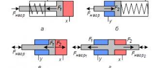
- unilateral action (due to fluid pressure, the moving link moves in one direction, and in the opposite direction it moves under the action of the return mechanism);
- double-acting (under the influence of working fluid pressure, the working stroke is carried out in both directions);
- piston hydraulic cylinders with single-sided and double-sided rods;
Hydraulic cylinders are used in such areas as road construction, hoisting and transport machines, earth-moving, drilling equipment, and technological equipment (machine tools, presses, etc.)
How does a hydraulic cylinder work?
Hydraulic cylinders are essentially volumetric hydraulic motors designed to convert fluid energy into mechanical energy that provides translational motion. The output (moving link) can be either the rod or the cylinder body (liner).
Depending on the working cycle, speeds and forces that the working parts of road-building, municipal, and forestry equipment must develop, different types of hydraulic cylinders are used with different methods of their inclusion in the hydraulic circuit of the volumetric drive.
What is a stock
The hydraulic rod is the main part of the hydraulic cylinder. It is a long, steel rod with a round cross-section, partially located inside a volumetric hydraulic motor. You can buy a hydraulic rod at a good price on the company’s website krpms.ru.
At the end of the “inner” part there is a place for the plunger (a piston that fits tightly to the walls of the sleeve and divides it into sections isolated from each other), and at the “outer” there is a mount for the mechanism to which the force must be transmitted.
During operation, the rod undergoes strong mechanical loads, under which even minor defects (cracks, longitudinal micro-strips from abrasive wear) can lead to a violation of the tightness of the sleeve chamber and the release of working fluid.
All high-quality parts are chrome-plated - it significantly increases wear resistance, reduces friction and protects against corrosion.
Types (classification) of hydraulic cylinders
Hydraulic cylinders can be divided into two types according to their design: single-sided and double-sided.
In the first case, the movement of the output shaft under the action of the working fluid is possible only in one direction, and in the second, the movement of the rod under the action of the working fluid is carried out in two opposite directions.
Double-acting cylinders are manufactured with a single-sided, double-sided or telescopic rod; they can also be equipped with a damping device that reduces the speed of movement of the output link at the end of the stroke.
To drive the working parts of excavators, cranes, loaders and other mobile machines, double-acting cylinders with a single-sided rod are most widely used. The force on the rod and its movement can be directed in both directions, depending on which of the cavities the working fluid is injected into.
The main parameters of hydraulic cylinders are nominal pressure, piston diameter and stroke. The last two determine the force developed by the hydraulic cylinder at a given pressure.
Domestic-produced earth-moving, leveling, land reclamation, municipal, peat-extraction, fire-fighting, load-lifting and hoisting-and-transport machines usually operate at nominal pressures of 10, 16, 25, 32 MPa, and the peak values of this series are 20, 32, 40, 50 MPa with speeds rod, not exceeding 0.5 meters per second.
One of the main parameters when choosing a hydraulic cylinder is the level of nominal pressure. However, when assessing the technical life, the operating modes of the cylinders at maximum and peak pressures are decisive.
Differential connection of hydraulic cylinder
When operating technological equipment, such as machine tools, it is often necessary for the hydraulic drive to operate in the following modes: fast approach, working stroke, fast withdrawal. This scheme can be implemented without the use of additional pumps and hydraulic accumulators using a differential connection of a hydraulic cylinder.
A double-acting hydraulic cylinder can be connected using a differential circuit; due to the difference in effective areas, it is also called differential; it is usually recommended to use a cylinder with an effective area ratio of 2:1, but you can deviate from this ratio, if necessary.
To connect the hydraulic cylinder using a differential circuit and obtain the desired operating cycle, you will need a special three-position distributor.
In extreme positions, the distributor will connect the pressure line with one of the cavities of the hydraulic cylinder, and the other with the drain line, but in the neutral position the distributor will connect both cavities of the cylinder with the pressure line, this will allow the implementation of a differential scheme.
The figure shows a diagram of a hydraulic drive with the possibility of connecting a hydraulic cylinder using a differential circuit.
Pump H1 supplies liquid from the tank, the pressure in the system is limited by the setting of the safety valve KP1, and a two-line regulator PP1 is used to regulate the flow. The liquid from the pump, through the regulator, enters the input of the distributor P1, to which the double-acting hydraulic cylinder GC1 is connected with an effective area ratio of 2:1.
According to the conditions of use, hydraulic cylinders are divided into three main groups:
- for driving lever mechanisms of working equipment, performing repetitive cyclically useful work (single-bucket excavators, front-end loaders, timber loaders);
- for moving working parts, performing useful work while moving (scrapers, motor graders, bulldozers);
- for installing working bodies in a certain position or installing outriggers to ensure a stable position of the machine.
Hydraulic cylinders can be manufactured for moderate (U1), cold (HL1), dry (TC1) and humid (TV1) tropical climates.
Below is the structure of the symbol for piston hydraulic cylinders of a unified design according to OST 22-1417-79:
According to the method of fastening the rod and sleeve, hydraulic cylinders can be divided into the following groups:
- 1. On lugs with articulated bearings
- 2. On the eye with a spherical bearing and a journal on the body
- 3. On the eye with a hinged bearing and with the preparation of the rear cylinder cover for welding with the mating structural element
- 4. With the outer end of the rod prepared for welding with a mating part and on the eye with a hinged bearing
- 5. With the preparation of the outer end of the rod for welding with the required part and with fastening
- 6. With preparation for welding of the outer end of the rod and the rear cover of the hydraulic cylinder with the required parts
Depending on the manufacturer, the layout of the elements of this circuit may vary.
Here are examples of hydraulic cylinder designations:
TsG-125×80×1000.11 manufactured by JSC "ELETSGIDROAGREGAT" where 125 piston diameter, 80 rod diameter, 1000 working stroke, 11 design: lugs with articulated bearing on the body and rod
G-150.125.56.400G manufactured by JSC "SDM" Orel where piston diameter is 125, rod diameter is 56, stroke is 400
Moreover, the plant that produces the machine often uses its own separate product markings, for example: the G-150.125.400G engine also has the designation TO-30.44.10.000, which is used directly by the plant that produces the TO-30 loader.
All features of markings and symbols must be reflected in the corresponding accompanying documentation of a particular hydraulic cylinder manufacturer.
Differential cylinder
Differential cylinders with the same traction forces require the use of large piston diameters. However, an increase in the number of working edges of follower spools sharply complicates and increases the cost of their production with the required high precision (on the order of microns), and an increase in losses in circuits with one working edge increases vibration resistance. [1]
Differential cylinders with a thin rod1 are widely used in broaching machines, as a result of which the idle time is only 10 - 15% of the working stroke time. [2]
In differential cylinders, movement in one of the directions can be carried out at equal pressures in both cavities of the cylinder due to the difference in the areas of the latter. [3]
With a differential cylinder and a thin rod (Fig. 11.112, b), during the working stroke, oil is supplied to cavity 2, and with a fast stroke, both cavities of the cylinder are connected to the discharge cavity of the pump. Since the active area of the piston in cavity / is greater than the active area of the piston in cavity 2, then at the same pressure that is established in both cavities, the force acting on the surface of the piston in cavity / will be greater than the force acting on the surface of the piston in cavity 2 , and the piston will move to the right. [5]
With a differential cylinder, the system is in most cases more stable with a small piston diameter in the direction of movement, when the throttle is included in the small cavity of the cylinder. [6]
Differential cylinder actuators have different cavity areas, while non-differential cylinder actuators can have equal or any cavity area ratios and be equipped with rotary hydraulic motors. [7]
Systems with a differential cylinder are used in two types: with double-lip and single-lip spools. [8]
Systems with differential cylinders are simpler and cheaper to manufacture, but do not provide high copy accuracy, are less rigid and consume more energy. Therefore, these systems are most appropriate to use in all cases where high demands are not placed on copying accuracy and rigidity, as well as where there are no alternating loads. [10]
Now we can outline an approximate algorithm for selecting a hydraulic cylinder:
- 1. Based on the layout conditions, find the connecting and overall dimensions
- 2. From the external load conditions, determine the calculated value of the force of the hydraulic cylinder driven to the rod
- 3. Select the diameter of the hydraulic cylinder with the force required to overcome the external load
- 4. Determine the design of the hydraulic cylinder and the method of its fastening
- 5. Determine the stroke of the hydraulic cylinder rod
- 6. To ensure the required force, select the nominal pressure
- 7. Select a cylinder with the required piston and rod diameter taking into account the speed value
- 8. Based on the specified speed of movement of the rod, the flow rate of the working fluid is determined
Looking for a hydraulic cylinder? Our specialists will always help you with your choice.
Select a hydraulic cylinder
Implementation of operating mode: fast approach, working stroke, fast retraction
We looked at the operation of a hydraulic cylinder when it is connected according to a differential circuit, let's figure out how the hydraulic drive will work in the fast approach, working stroke, fast withdrawal modes.
Quick approach
The distributor spool is in the neutral position, the hydraulic cylinder is connected according to a differential circuit, its rod extends with increased speed and reduced force.
Working stroke
The distributor switches to the right position, fluid from the pump enters the piston cavity, and from the rod cavity it is directed to drain, the hydraulic cylinder rod of the hydraulic cylinder moves with high force and low speed. A technological operation is being performed.
Quick retraction
The distributor switches to the left position.
The liquid from the pump enters the rod cavity, and the piston cavity is connected to the drain, the hydraulic cylinder rod begins to retract. Since the volume of the rod cavity is smaller than the piston cavity, with the same pump flow, the hydraulic cylinder rod will move faster.
Source
Diagram (design) of a hydraulic cylinder
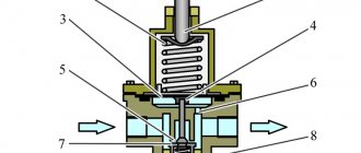
Structurally, a hydraulic cylinder consists of the following main parts: sleeve, piston, rod, guide bushing, cover, eye and support and guide elements (cuffs, rings, wipers, etc.).
It is worth writing a few words about the operation of hydraulic cylinders.
During installation and operation, the rules of safe operation determined by GOST, as well as the operating instructions for the machine, must be observed.
Before installing the hydraulic cylinder on the machine, it must be unpreserved. When installing hydraulic cylinders on articulated bearings, the deviation of its geometric axis should not exceed 2 degrees in one direction. When lubricating bearings through the support pins, the lubrication grooves must align with the lubrication holes in the inner ring of the bearing.
After installing the hydraulic cylinder, the hinge bearings must be lubricated with universal medium-melting grease until it appears in the bearing gaps.
During the first 8 hours of operation, the pressure in the hydraulic cylinders should not exceed 50% of the nominal value.
When the rod of a new cylinder is heated or after adjusting the axial compression of the multi-row seal package, it is necessary to loosen the seals by installing an additional gasket under the front cover.
When hydraulic cylinders operate, the rods must move smoothly, without jolts or jamming; There should be no external leaks of working fluid along the rod and at the junction of the supply pipelines.
Still have questions? Our managers are always ready to help.
To get a consultation
Subscribe to us!
Send the article to yourself by email
Technical characteristics of hydraulic cylinders
The scope of application of the mechanism, as well as the period of its trouble-free operation, depend on the characteristics and parameters of the unit. It is important to know what it consists of so that, if necessary, you can easily purchase a replacement for the faulty part.
Main operating parameters:
- The diameter of the rod is a fairly important parameter that determines the scope of operation of the product. When choosing, it is important to focus on the type of equipment in which it will function. When designing a hydraulic system for a specific vehicle, it is imperative to take into account the dynamics of the load on the mechanism, as well as its load-carrying capacity. This eliminates bending of the rod during operation of the hydraulic cylinder.
- The diameter of a cylindrical rod, the main function of which is to determine the value of pulling and pushing forces;
- characteristics of the stroke of the cylindrical rod - a parameter that determines the movement of the piston and the dimensions of the mechanism in working condition.
- design features that allow you to determine how to attach the hydraulic cylinder.
- pulling force (kg).
- non-operating distance on centers that provide an effective assessment of the connecting dimensions of the unit.
- nominal pressure, calculated in MPa.
- pushing force (kg).
- the mass of the product itself.
