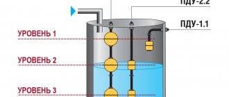
Liquid level sensors in the tank allow you to both perform a current measurement of the amount of liquid filled and report when its limit values have been reached. Such devices consist of a sensitive sensor that responds to certain physical parameters, and a measurement, control and indication circuit. Depending on the area of application, devices are used that differ in their operating principles.
The information presented in the article will help you learn about the operating principles of different types of sensors and their areas of application. A brief overview of their advantages and disadvantages will be carried out, and the main manufacturers that have proven themselves on the market will be indicated.
Classification of devices
Liquid level sensors in a tank can be level meters or alarms. The first of them are designed to continuously measure the liquid level at the current time. They use sensors that operate on different physical principles. Further processing of the signals coming from them is carried out by analog or digital electronic circuits that are part of the level gauges. The obtained indicators are displayed on the display elements.
Alarms warn when a certain value of the liquid level in the container, preset by the setting elements, has been reached. Another name for them is water level sensors in the tank to shut off its further supply. Their output signal is discrete. The warning may be provided in the form of a light or sound alarm. In this case, the operation of the filling or draining systems is automatically blocked.
Float water level gauges
An economically feasible solution for level monitoring up to 1.5...2 meters with an accuracy of ±5 mm. Highly accurate water level measurement solution for custody transfer metering. Visual sensor combined with an electronic level gauge for boilers and pressure tanks.| Modification | Photo | Switching function | Switching voltage | Switching current | Output element | Material | Ambient temperature | ||
| DC | A.C. | DC | A.C. | ||||||
| PDU-T101 | 220 V | 240 V | 0.7 A | 0.5 A | Reed switch | Stainless steel steel | -20…+125 °C | ||
| PDU-T102 | 220 V | 240 V | 0.7 A | 0.5 A | Reed switch | Stainless steel steel | -20…+125 °C | ||
| PDU-T104 | 220 V | 240 V | 0.7 A | 0.5 A | Reed switch | Stainless steel steel + polypropylene | -10…+80 °C | ||
| PDU-T106 | 220 V | 240 V | 0.7 A | 0.5 A | Reed switch | Polypropylene | -10…+80 °C | ||
| PDU-T121-065-115 | 220 V | 240 V | 0.7 A | 0.5 A | Reed switch | Stainless steel steel | -20…+125 °C | ||
| PDU-T301 | 220 V | 240 V | 0.7 A | 0.5 A | Reed switch | Stainless steel steel | -20…+125 °C | ||
| PDU-T302 | 220 V | 240 V | 0.7 A | 0.5 A | Reed switch | Stainless steel steel | -20…+125 °C | ||
| PDU-T321-060-110 | 220 V | 240 V | 0.7 A | 0.5 A | Reed switch | Stainless steel steel | -20…+125 °C | ||
| PDU-T501 | 220 V | 240 V | 0.7 A | 0.5 A | Reed switch | Polypropylene | -10…+80 °C | ||
| PDU-T502 | 220 V | 240 V | 0.7 A | 0.5 A | Reed switch | Polypropylene | -10…+80 °C | ||
| PDU-T505 | 220 V | 240 V | 0.7 A | 0.5 A | Reed switch | Stainless steel steel | -20…+125 °C | ||
| PDU-T601-2 | 220 V | 220 V | 10 A | 10 A | Relay | Polypropylene | -10…+80 °C | ||
| PDU-T601-5 | 220 V | 220 V | 10 A | 10 A | Relay | Polypropylene | -10…+80 °C | ||
Level measurement methods
Depending on the properties of the liquid whose level in the tank needs to be determined, the following measurement methods are used:
- contact, in which there is direct interaction of the liquid level sensor in the tank or its part with the measured medium;
- non-contact, allowing to avoid direct interaction of the sensor with the liquid (due to its aggressive properties or high viscosity).
Contact devices are located in a container directly on the surface of the liquid being measured (floats), in its depth (hydrostatic pressure gauges), or on the tank wall at a certain height (plate capacitors). For non-contact meters (radar, ultrasonic), it is necessary to provide a zone of direct visibility of the surface of the liquid being measured and the absence of direct contact with it.
Criterias of choice
There are certain features that must be taken into account when classifying a sensor. They are listed below:
- Accuracy.
- Environmental conditions - usually sensors have restrictions on temperature and humidity.
- Range—the sensor's measurement limit.
- Calibration is necessary for most measuring instruments because readings change over time.
- Price.
- Repeatability—variable readings are measured repeatedly in the same environment.
Operating principles
Both level gauges and alarms use different operating principles to perform their functions. The most common types of devices are:
- float sensors for liquid level in the tank;
- capacitive;
- hydrostatic liquid level sensors;
- radar type devices;
- ultrasonic sensors.
Float valves, in turn, can be mechanical, discrete and magnetostrictive. The first three groups of sensors include devices using the contact measurement method, the other two belong to non-contact devices.
Purpose of level gauges for capacitive-type liquids
Capacitive-type level measuring devices can be used to take measurements in tanks, storage facilities, pipes, and fuel tanks. They allow you to determine the current liquid level or track continuous changes in the level. There are also models that can provide measurements in deep tanks and wells or are suitable for non-contact control. In conjunction with additional sensors, such devices can transmit information to external equipment or ensure that the level of the monitored liquid remains stable.
Mechanical float sensors
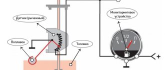
A light float, constantly located on the surface of the liquid in the tank, is connected by a system of mechanical levers to the middle terminal of the potentiometer, which is the arm of the resistance bridge. With a minimum amount of liquid in the container, the bridge is considered balanced. There is no voltage in its measuring diagonal.
As the reservoir fills, the float monitors the position of the liquid level by moving the movable contact of the potentiometer through a system of levers. Changing the resistance of the potentiometer leads to an imbalance in the bridge. The voltage that appears in its measuring diagonal is used by the electronic circuit of the display system. Its analog or digital readings correspond to the amount of liquid in the tank at the current time.
Work with various devices
The operating principle and classification of temperature sensors are also divided into the use of technology in other types of equipment. These could be dashboards in a car or special production units in an industrial workshop.
- Thermocouple modules are made of two wires (each from a different homogeneous alloy or metal) that form a measuring junction by connecting at one end. This measuring unit is open to the elements being studied. The other end of the wire ends with a measuring device, where a reference junction is formed. Current flows through the circuit because the temperature of the two connections is different. The resulting millivolt voltage is measured to determine the temperature at the junction.
- Resistance temperature detectors (RTDs) are types of thermistors that are manufactured to measure electrical resistance as temperature changes. They are more expensive than any other temperature detection devices.
- Thermistors. They are another type of thermal resistor in which a large change in resistance is proportional to a small change in temperature.
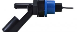
Discrete float sensors
A discrete signal in the form of closing or opening the reed relay contacts is used by the electronic indication and signaling circuit to notify that the liquid level in the container has reached a certain value. Metal contacts, made of a material with low contact resistance when they are closed, are placed in a hollow, insulated glass bulb.
A water level sensor in a tank with a discrete output includes a guide in the form of a hollow tube into which liquid from the tank does not enter. The contacts of one or more reed relays are fixed inside the guide. Their location depends on the case in which it is necessary to receive an alarm when the liquid level reaches a given value.
The sensor float with a small permanent magnet built into it moves along the guide when the liquid level in the container changes. The contact group is triggered when it enters the magnetic field of the permanent magnet of the float. The signal through the wires connected to the contacts of the water level sensor in the reed switch tank is sent to the alarm circuit.
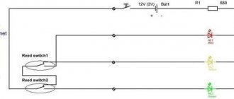
Parts List
- You can use any of these transistors: KT815A or B. TIP29A. TIP61A. BD139. BD167. BD815.
- GK1 – lower level reed switch.
- GK2 – upper level reed switch.
- GK3 – emergency level reed switch.
- D1 – any red LED.
- R1 – resistor 3Kom 0.25 watts.
- R2 – resistor 300 Ohm 0.125 watt.
- K1 – any 12 volt relay with two pairs of normally open contacts.
- K2 – any 12 volt relay with one pair of normally open contacts.
- I used float reed contacts as signal sources for replenishing water in the container. The diagram is designated as GK1, GK2 and GK3. Made in China, but of very decent quality. I can't say a single bad word. In the container where they stand, I treat the water with ozone and over the years of work there has not been the slightest damage to them. Ozone is an extremely aggressive chemical element and it dissolves many plastics completely without any residue.
Now let's look at the operation of the circuit in automatic mode. When power is supplied to the circuit, the lower level float GK1 is activated and power is supplied to the base of the transistor through its contact and resistors R1 and R2. The transistor opens and thereby supplies power to the relay coil K1. The relay turns on and with its contact K1.1 blocks GK1 (lower level), and with contact K1.2 it supplies power to the coil of relay K2, which is an actuator and turns on the actuator with its contact K2.1. The actuator can be a water pump or an electric valve that supplies water to the container. The water is replenished and when it exceeds the lower level, GK1 turns off, thereby preparing the next cycle of work. Having reached the upper level, the water will raise the float and turn on GK2 (upper level), thereby closing the chain through R1, K1.1, GK2. The power to the base of the transistor will be interrupted, and it will close, turning off relay K1, which with its contacts will open K1.1 and turn off relay K2. The relay, in turn, turns off the actuator. The circuit is prepared for a new cycle of work. GK3 is an emergency level float and serves as insurance if the upper level float suddenly does not work. Diode D1 is an indicator that the device is operating in water filling mode. Now let's start making this very useful device.
We place the parts on the board.
We place all the parts on a breadboard so as not to make a printed one. When placing parts, you need to take into account to solder as few jumpers as possible. It is necessary to make maximum use of the conductors of the elements themselves for installation.
Final look.
The water level control circuit is sealed.
The circuit is ready for testing.
We connect it to the battery and simulate the operation of the floats.
Everything is working fine. Watch a video about tests of this system.
Source: SdelaySam-SvoimiRukami.ru
Magnetostrictive float sensors
Sensors of this type produce a constant signal depending on the level of liquid in the tank. The main element, as in the previous case, is a float with a permanent magnet inside, which takes its position on the surface of the liquid and moves in a vertical plane along the guide.
The inner cavity of the guide, isolated from the liquid, is occupied by a waveguide. It is made of magnetostrictive material. At the bottom of the element there is a source of current pulses that propagate along it.
When the emitted pulse reaches the location of the float with the magnet, the interaction of two magnetic fields occurs. The result of this interaction is the occurrence of mechanical vibrations that propagate back along the waveguide.
A piezoelectric element is attached next to the pulse generator, which records mechanical vibrations. An external electronic circuit analyzes the time delay between the emitted and received pulses and calculates the distance to the float, which is constantly located on the surface of the liquid. The display circuit constantly reports the liquid level in the tank.
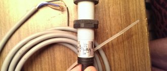
Contactless water sensor Y25 T12V, or Stop making holes in barrels
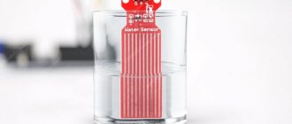
I have published many reviews about dacha automation, many of which involved manipulation of water. Often you need to find out the fluid level, or the fact that it is missing. It is convenient to use such information in your crafts aimed at getting rid of routine procedures. To find out the level, many people, including me, use float sensors on reed switches, the main problem when using them is the need to make holes in the container; you must agree, this does not add reliability and versatility to the use of the container, and drilling with subsequent sealing is not the most pleasant manipulation . The device under review (which went on sale recently) is designed to get rid of this, ensuring scalability and configurability of the system... Let's see what kind of beast is under the cut. The sensors arrived in 14 days and were packaged quite well. The sensors themselves in bags:
Unpacking:
Lace length is about 45 cm: Dimensions:
The connector has 4 contacts:
From left to right: - brown - power - yellow - signal - blue - ground - black setting The sensor has an indicator that, when water is detected, should light up, judging by the seller’s description. The sensor can be powered in the range from 5 to 24 Volts, which is very convenient. The housing is waterproof (ip67), which allows you to place the sensor outdoors or in a damp room without worrying about its protection. In order not to immediately break the connector, let’s connect the model wiring:
At my dacha I have a homemade adjustable power supply built into the wall, let’s connect the power, 12 Volts:
We bring it to a bottle of water, the indicator lights up:
If you raise it above the water level, the indicator goes out:
By the way, if you lean your hand, the indicator also lights up:
Let's connect the multimeter to the power cables and make sure it's working.
Next: minus to ground, and plus to signal output:
We bring it to the bottle and see the supply voltage at the output:
If you remove the sensor, the voltage at the signal output disappears:
The output current of the sensor is in the range of 1-50 mA. The seller states that it works with a power supply in the range of 5-24 Volts, let's try to reduce the supply voltage to 4 Volts: The sensor works fine, let's try to reduce it to 3 Volts:
The reliable operation of the sensors allows us to conclude that it can be successfully used with the esp8266 without any conversions - and this is great news! At other voltages, the sensor also works well:
I did not dare to go beyond 24 Volts. Let's set it to 5 Volts:
The sensor reacts to its bag:
The side of the bottle cap also reacts:
Glue it to the bottle with 3M double-sided tape:
The sensor responds perfectly. With two layers of tape, the sensor does not always work:
Consumption is about 5-6 mA:
And of course, we’ll try to apply it in real conditions, working with a controller. Let's take an Arduino Nano as a controller, and also add an indicator LED, so we get the following kit:
We will connect the LED to pin D3 and ground, and the signal output of the sensor to pin A0 (D14 - since we will use it in digital mode), and we will also supply power to the sensor from the controller:
Considering that the sensor is designed for water, when working with it it is very important to protect yourself from contact chatter, for example during waves when the pump is running. Also, I will show how to organize such protection without using delays in the program, the actual code: // Current state of the sensor bool SensorState = false; // Shift start time unsigned long SensorStartChange = 0; // Guard interval between state changes unsigned long TIMEOUT = 3000; // Current time unsigned long CurrentTime = 0; void setup() { // LED is an output pinMode(LED_PIN, OUTPUT); // Don't turn on the light at first digitalWrite(LED_PIN, LOW); // The sensor is an input pinMode(SENS_PIN, INPUT); } void loop() { // Set the current time CurrentTime = millis(); // read the sensor boolean CurrentState = digitalRead(SENS_PIN); // if the current state of the sensor differs by the amount read if (CurrentState != SensorState) { // if the state change timer has not started, start if (SensorStartChange == 0) SensorStartChange = CurrentTime; // if the new state took on its value in a time greater than the timeout time if (CurrentTime - SensorStartChange > TIMEOUT) { // change the sensor state SensorState=!SensorState; // reset the start time of the state change SensorStartChange = 0; // if the current sensor state is 1, then turn on the LED if(SensorState){ digitalWrite(LED_PIN, HIGH); // if the current state of the sensor is 0, then turn off the LED }else{ digitalWrite(LED_PIN, LOW); } } // the state change did not take place, reset the timer }else{ SensorStartChange = 0; } } I commented out all the lines to make everything clear. We initialize the outputs and check the change in the state of the signal output of the sensor with contact bounce protection. In this code, the guard interval is 3000 ms = 3 seconds, often it is advisable to increase this interval to a minute to eliminate the influence of waves from the pump. The code is simple, but on its basis it is easy, for example, to organize protection against dry running of the pump (it is very undesirable for most pumps to operate without water), such devices cost an unreasonable amount of money, but here you can get by with little expense, and even implement automatic recovery of the pump when water and a number of other pleasant goodies - such as indication. To do this, you need to glue such a sensor or somehow secure it closer to the bottom of the container, and connect the pump through a relay controlled by the controller. By default, the pump will be turned on; as soon as the sensor recognizes the lack of water, the controller will turn off the pump, and when water appears, it will turn it on. It is also possible to organize protection against leaks on this sensor, especially considering its moisture resistance; in general, everyone can adapt this simple code to their needs. And most importantly, the sensors can be moved around the container without damaging it - by adjusting the levels to suit you. Video illustrating the operation of the sensor and controller with the specified code:
I put together this layout for testing different capacities:
I walked around the dacha plot with the model, and the sensor was able to detect water in all non-metallic containers, including a rather thick-walled bucket. Therefore, at the current stage I can fully recommend it; time will tell about its reliability.
The sensor response time is about 500 ms. The wall thickness of a dielectric vessel can reach 1 cm.
The principle of operation of the sensor is to change the capacitance from the parasitic capacitance of water; at a certain threshold, resonance occurs and the sensor is triggered. Supply voltage in the range from 3 to 24 Volts does not affect sensitivity in any way.
They asked to check the sensitivity, so this illustration is better than any words:
It will work great as a leak sensor.
Various photos upon request
There’s no way with this at all - left alcohol: fairy:
thick canister 40 liters:
distilled water:
strong alcohol:
cooler bottle at its thickest point:
white spirit - no:
Through the ceramic toilet tank it is easy to find water:
I opened the lid, the inside was filled with compound, but there was a potentiometer output; after twisting it to the right, the sensor stopped responding to water; after twisting it to the left, it began to respond to lateral finger touches, it looks like this is adjusting the sensitivity.
If there is interest, I will continue to write about my country crafts. Thanks to everyone who read this review to the end, I hope someone finds this information useful. Full control over your water resources and goodness to everyone!
Capacitive sensors
The operation of sensors of this type is based on the properties of a capacitor to change its electrical capacitance when the dielectric constant of the material filling the space between its plates changes. Coaxial type capacitors are used, which are a pair of coaxial hollow metal cylinders of different diameters.
The latter are the plates of the capacitor, between which liquid can freely penetrate. The dielectric constants of air and liquid media have different values. Filling the reservoir leads to a change in the value of the total dielectric constant of the coaxial capacitor and, accordingly, its electrical capacitance.
The frequency of the oscillatory circuit, in the circuit of which the capacitor is connected, changes in proportion to the change in its capacitance. An electronic frequency/voltage converter monitors this change and displays a value proportional to the degree of filling of the tank.
Features of application
The use of ultrasonic meters has a number of features. For example, to eliminate measurement errors, you must follow the algorithm:
- carry out calibration of the device when the composition of the gaseous medium changes to establish the actual speed of sound;
- carry out calibration at each significant change in temperature, recording the speed values;
- In the future operation of the device when temperature changes occur, do not carry out calibration, but use previously recorded speed indicators.
The process of setting up the sensor is quite labor-intensive. A situation is possible when changes in the gas environment in the tank are not associated with changes in temperature. In this case, you will have to recalibrate the device.
Hydrostatic sensors
Another name for such a device is a detector, or pressure transducer. They can be stationary, fixed at the bottom of the container filled with liquid, or portable. In the latter case, the pressure transducers are equipped with a cable of considerable length. This allows them to be used for tanks of different geometric sizes.
The sensing element of a hydrostatic sensor is a membrane that senses the pressure of a liquid column above it. It is configured in such a way that atmospheric pressure does not lead to deformation of the membrane. Based on the pressure at the measurement point, you can determine the height of the liquid column or the degree of filling of the tank.
The amount of membrane deformation is converted into a proportional electrical indicator, which is then used to display the level of liquid in the reservoir. Corrections are applied that take into account the density of the measured medium and the acceleration of gravity at the measurement point.
Varieties by type
There is a wide range of criteria by which level sensors can be classified. Starting from the principle of operation and ending with the method of signal transmission. However, all sensors can be divided into two large groups – contact and non-contact.
Contact
A contact sensor is a device that requires physical contact with the surface being measured to function. As a rule, such sensors are used under conditions of exposure to factors that significantly complicate measurements - high temperature or pressure. They are also widely used for working with foaming liquids, where the top layer can introduce a significant error when measuring by other methods. All contact devices can be divided into the following types according to the principle of operation:
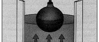
- Capacitive - consist of two plates immersed in liquid. Measurements are made on the principle of a capacitor, whose capacitance will vary depending on the height of the liquid filling of the space between the capacitor plates. Often used for containers with small volumes of liquid. They are characterized by low measurement accuracy, but operate without moving parts, which significantly increases their reliability.
Rice. 3. Capacitive sensor
- Hydrostatic - based on Pascal's law. Measures the difference in hydrostatic pressure in the tank, which depends solely on the height of the liquid column. They have good accuracy, but can only be used in containers where the pressure is comparable to atmospheric pressure. They are not suitable for liquids with variable densities.
Rice. 4. Hydrostatic sensor
- Bypass - use the principle of communicating vessels; in such sensors, information about the level of the measured liquid is displayed most clearly. When the column height in the main tank changes, the sensor will display this data on its own level gauge. However, such models are not used in conditions above +250°C and in environments that increase their own viscosity with decreasing temperature.
- Magnetic sensors are a subtype of float sensors, since the liquid level is measured by a float moving along a hermetically sealed tube. There is a reed switch inside the tube, which is triggered when a float with a magnet approaches or moves away.
- Reflex microwave - the operating principle of such sensors is based on reflectometry technology depending on the time interval. The directional wave emitter sends a signal, and the sensor perceives the speed of return of the pulse.
Rice.
5. Reflex microwave liquid level sensor The main disadvantage of these models is the need to immerse the device throughout its entire depth, which is not always convenient for large tanks. But, unlike other liquid level sensors, reflex models do not depend on the presence or absence of foam, solid particles floating in the thickness or on the surface, or dielectric constant.
Contactless
Non-contact sensors are devices that do not require physical contact with the surface being measured to function. Such devices are used in aggressive liquid environments, where rapid wear of sensor elements is possible due to the influence of active components. They are also installed in viscous liquids and environments with high viscosity. All contactless sensors are conventionally divided into the following categories:
- Ultrasonic is one of the most common types of non-contact liquid level sensors. The principle of operation is based on the ability of a liquid to reflect the ultrasonic spectrum of radiation. An ultrasound generator, inaudible to the human ear, sends a signal from the top point to the interface between the media. When it encounters a liquid, the signal is reflected and returned to the sensor, where it is sensed by the sensor. Depending on the time of movement of the ultrasound, a conclusion is made about the level in the tank.
- Microwave radar - similar to the previous option, except that the object of measurement is not ultrasound, but microwaves.
Rice.
6. Radar microwave liquid level sensor A significant disadvantage of radar-type sensors is their susceptibility to gas cushions that can accumulate above the surface of the liquid.
- Radioisotope - use gamma radiation to control the liquid level, particles are directed into a controlled reservoir.
Rice.
7. Radioisotope sensor Due to the danger of exposure to living organisms, it is the most expensive and least common option. When using it, additional safety measures are required for operating personnel.
Radar type sensors
The container liquid level sensor uses a non-contact measurement method based on the properties of this medium of any density and viscosity to reflect an electrical signal. The frequency of the emitted signal from a radar located above the surface of the measured liquid level changes according to a linear law.
Reflected from the surface, it arrives at the receiving device with a delay determined by the length of the path traveled. Thus, there is a difference between the frequencies of the two signals. Based on the frequency shift, the radar analyzing device determines the path traveled by the signal or the level of the reflecting liquid relative to the location of the radar.
Reflex radar level gauge
Measuring principle
The measuring principle of the reflex radar TDR level meter is based on time domain reflectometry technology (TDR - “Time Domain Reflectometry”). Often such devices are also called level gauges with a guided wave, contact type (GWR - “guided wave radar”). With this measurement method, low-power electromagnetic pulses with a duration of about 1 nanosecond propagate along a waveguide (most often a rod or several rods, a cable, a coaxial structure). Pulses move at a speed determined by the characteristics of the propagation medium, the geometry of the waveguide - as a structure for the propagation of electromagnetic radiation. In the case of propagation in air under normal conditions, the speed of propagation is considered equal to the speed of light. The propagation speed is inversely proportional to the square root of the dielectric constant of the propagation medium [1]. In the case of pulses propagating through a layer of medium whose dielectric constant is close to 2 (including all petroleum products), the propagation speed will decrease by 1.414 times. Having reached the surface of the controlled product, the pulses are reflected from the interface, and the intensity of the reflection also depends on the dielectric constant of the product εr (for example, up to 80% of the initial pulse level is reflected from the water surface, for light oil products - about 17%). The device measures the time interval between the moments of emission and reflection of pulses. Half of this time corresponds to the distance between the reference point (the sealing surface of the flange is often taken as the reference point) and the surface of the measured medium. This temporary value is converted into an output signal of the required type, for example 4...20 mA and/or discrete signals, or stored in a readable/accessible form using digital interfaces/protocols (for example RS-485, Modbus RTU, HART, etc. .). A feature of devices of this type is the ability to measure the interfacial level simultaneously with measuring the level of the main product, without the use of moving parts. Some devices of this type conveniently combine level and temperature measurement of the product. Dust, foam, fumes, rough surfaces, boiling liquids, fluctuations in pressure and temperature, and density have virtually no effect on the operation of the device.
Ultrasonic level sensors
The measurement scheme used for sensors of this type corresponds to that discussed in the previous section of the article. The location measurement method is used in the ultrasonic wavelength range.
The received data determines the time difference between the signals emitted by the transmitter and the signals received by the receiver. Using data on the speed of propagation of ultrasound in the space above the surface of the liquid, the analyzing device determines the distance traveled by the signal or the level of liquid in the reservoir.